Delta OHM HD3406.2 User manual

Our instruments' quality level is the results of the product continuous development. This
can bring about differences between the information written in this manual and the instru-
ment that you have purchased. We cannot entirely exclude errors in the manual, for which
we apologize.
The data, figures and descriptions contained in this manual cannot be legally asserted. We
reserve the right to make changes and corrections without prior notice.
REV. 1.0
31 Jan. 2006
HD3406.2
- -
2
Conductivity meter – Thermometer
HD3406.2

- -
3
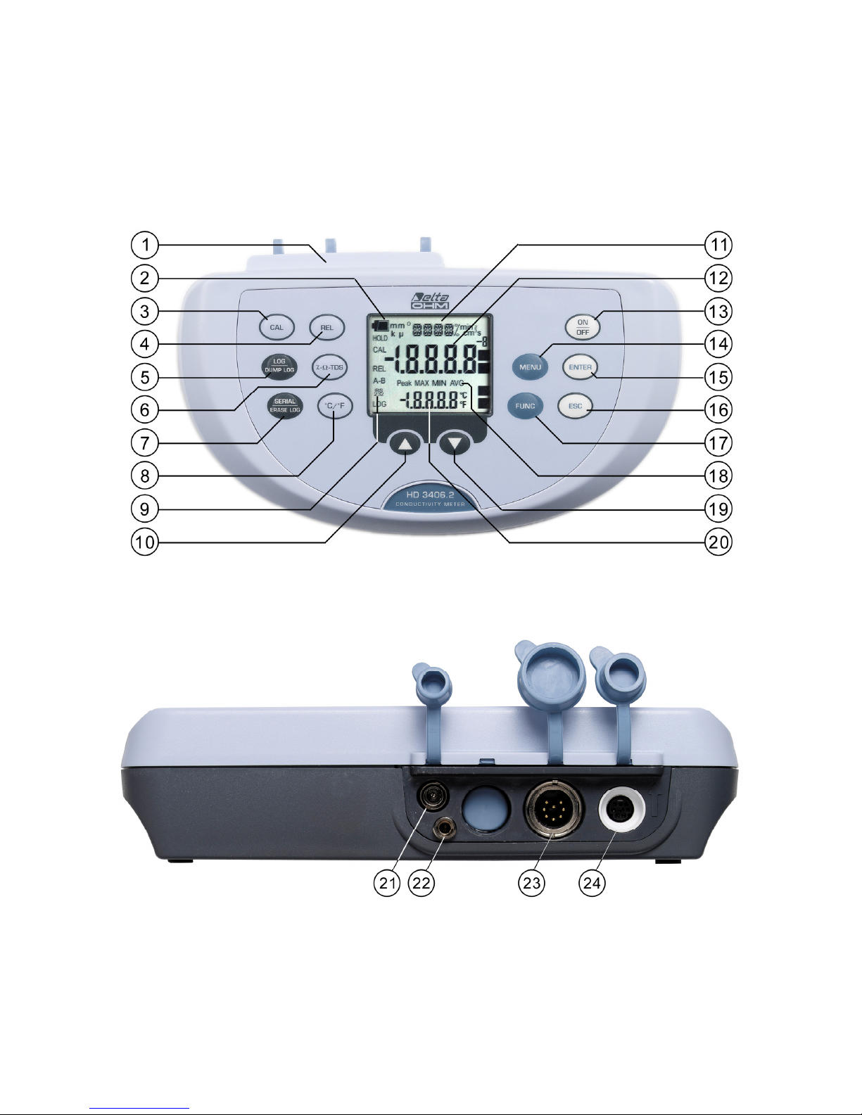
HD3406.2
1. Connectors.
2. Battery symbol: indicates the battery level. The symbol does not appear when the external
power supply is connected.
3. CAL key: it starts the conductivity probe calibration.
4. REL key: enables the relative measurement (displays the difference between the current va-
lue and the logged value when the key is pressed); in the menu, decreases the current value.
5. LOG/DUMP LOG key: during normal operation, starts and ends the saving of the data in
the internal memory; in the menu, starts the data transfer from the instrument's memory to
the PC.
6. χ-Ω-TDS Key: changes the main variable measurement between conductivity, resistivity,
total dissolved solids (TDS) and salinity.
7. SERIAL/ERASE LOG key: starts and ends the data transfer to the serial/USB communica-
tion port. In the menu, clears the data contained in the instrument's memory.
8. °C/°F key: when the probe is not connected, allows manual modification of the temperature.
When double pressed, changes the unit of temperature measurement from degrees Celsius to
Fahrenheit.
9. Function indicators.
10. key: in the menu, confirms the current selection.
11. Line for symbols and comments.
12. Main display line.
13. ON-OFF/AUTO-OFF key: turns the instrument on and off. When pressed together with the
ENTER key, disables the automatic turn off.
14. MENU key: allows access to and exit from the menu.
15. ENTER key: in the menu, confirms the current selection; when pressed together with the
ON/OFF key, disables the automatic turn off.
16. ESC key: in the menu, cancels the operation in progress without making changes.
17. FUNC: key: during normal operation displays the maximum (MAX), the minimum (MIN)
and the average (AVG) of current measurements.
18. MAX, MIN and AVG symbols.
19. Key : in the menu, decreases the current value.
20. Secondary display line.
21. External mains power supply connector input 12Vdc for ∅5.5mm - 2.1mm connector .
22. Not used
23. 8-pole DIN45326 connector, input for combined 4-ring or 2-ring conductivity/temperature
probes, for direct 4 wire Pt100 temperature probes and 2 wire Pt1000 probes complete with
TP47 module.
24. 8-pole MiniDin connector for RS232C connection using cable HD2110CSNM, for USB 2.0
connection using cable HD2101/USB, and for S-print-BT printer connection using cable
HD2110CSP.

- -
4
INTRODUCTION
The instrument series HD34… is made up of 4 bench top instruments for electrochemical measures:
pH, conductivity, dissolved oxygen, and temperature.
The HD3406.2 measures conductivity, liquid resistivity, total dissolved solids (TDS), and salin-
ity using combined 4-ring and 2-ring conductivity/temperature probes. Temperature is measured
by Pt100 or Pt1000 immersion, penetration or contact probes.
The probe can be calibrated either manually or automatically resorting to one or more of the 147μS,
1413μS, 12880μS or 111800μS/cm conductivity standard solutions
The displayed data can be stored (datalogger) and can be transferred to PC or serial printer thanks
to the multi-standard serial ports RS232C and USB2.0 and software DeltaLog9 (Version 2.0 or later
versions). The storing and printing parameters can be set from menu.
Display, printing and logging always show temperature in °C °F, and one of the parameters of con-
ductivity measure (χo Ωor TDS or NaCl).
Other common function of this instrument series include: Max, Min and Avg function, the Auto-
HOLD function, the automatic turning off which can also be disabled.
The instruments have IP66 protection degree.
- -
5
KEYBOARD AND MENU DESCRIPTION
Foreword
The instrument keyboard is composed of single-function keys, like the MENU key, and double-
function keys such as the LOG/DUMP LOG key.
In the double-keys, the function in the upper part is the "main function", while the one in the bottom
part is the "secondary function". When the instrument is in standard measurement mode, the main
function is active. The secondary function of the is enabled in the menu.
The pressing of a key is accompanied by a short confirmation beep: a longer beep sounds if the
wrong key is pressed.
Each key specific function is described in detail below.
ON-OFF key
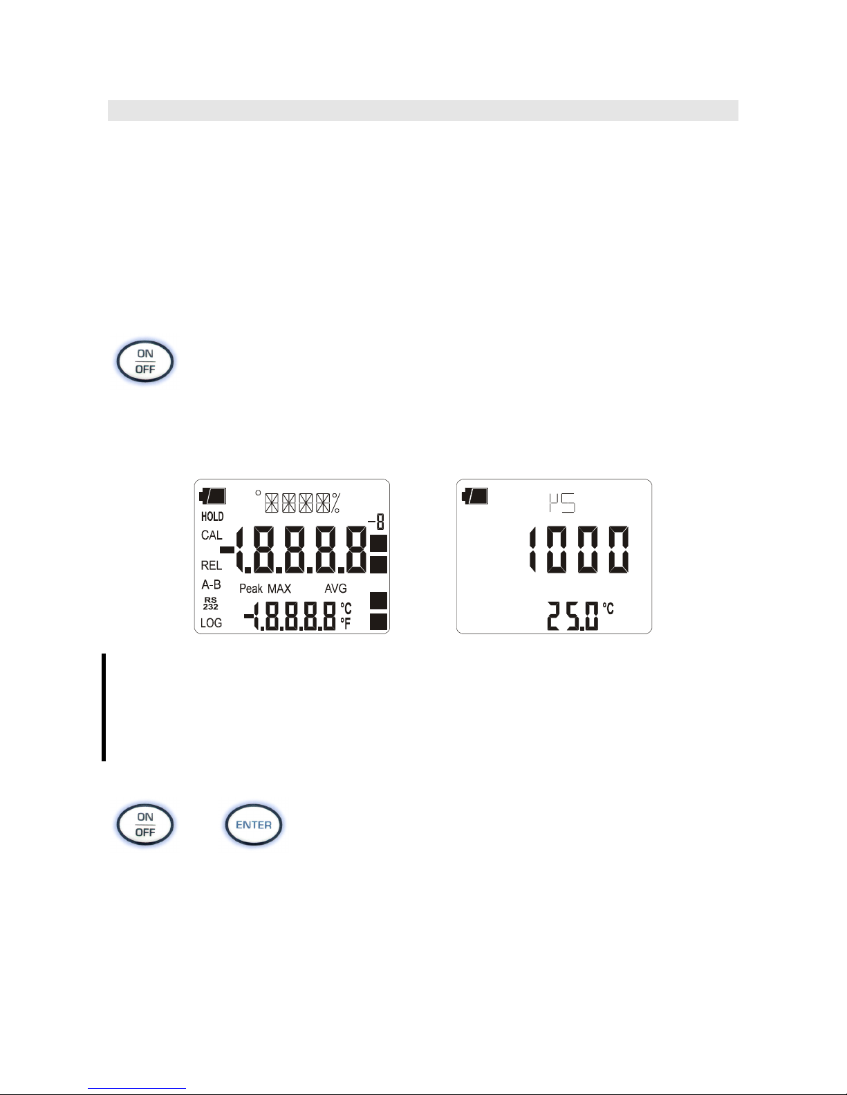
The instrument is turned on and off using the ON/OFF key. Turning on enables all display seg-
ments for a few seconds, starts an auto-test, and displays the current values of cell constant (CELL)
and temperature coefficient α(ALPH). Finally, it sets the instrument ready for normal measure-
ment.
MIN
cm
min s
2
3
m
µ
m
k
>>>
During turning on, should no probes be connected, the last manually-set temperature ap-
pears in the secondary line. The unit of measurement symbol (°C or °F) starts blinking,
and a letter "m" meaning "manual" appears next to the battery symbol.
The probe's data are captured upon turning the instrument on: if the ERR message ap-
pears in the secondary line, it is necessary to turn the instrument off and then on again.
Replace the probes when the instrument is off.
+
Automatic turning off
The instrument has an AutoPowerOff function that automatically turns the instrument off after about
8 minutes if no key is pressed during the intervening time. The AutoPowerOff function can be dis-
abled by holding the ENTER key: pressed down when turning the instrument on: the battery symbol
will blink to remind the user that the instrument can only be turned off by pressing the <ON/OFF>
key.
The automatic turning off function is disabled when external power is used. On the other
hand, it cannot be disabled when the batteries are discharged.

- -
6
ENTER Key
In the menu, the ENTER key confirms the current parameter and then goes to the next one. Pressed
together with the ON/OFF key, disables the automatic turn off.
MENU Key
The first menu item is accessed by initially pressing on the MENU key; press ENTER to go to the
following items. To modify the item displayed, use the arrow keys (and ). The current value is
confirmed by pressing the ENTER key and the display moves on to the next parameter. If pressing
ESC the setting is cancelled.
To exit the menu, press the MENU key at any time.
The menu items are listed in this order:
1) Management of memorized data: the message "LOG_DUMP_or_ERAS" (Transfer data
or erase) is scrolled in the comment line. The center figure reports the number of free mem-
ory pages (FREE). All memory data are permanently erased by pressing SE-
RIAL/EraseLOG. By pressing LOG/DumpLOG, the data transfer of the logged data on the
serial port is started: the "BAUD-RATE" must have previously been set to the maximum
value (please see the menu items described below and the paragraph "STORING AND
TRANSFERRING DATA TO A PERSONAL COMPUTER" on page 30).
2) sets the interval in seconds between two loggings or data transfers to the serial port. The in-
terval can be set from 0s, 1s, 5s, 10s, 15s, 30s, 60s (1min), 120s (2min), 300s (5min), 600s
(10min), 900s (15min), 1200s (20min), 1800s (30min) e 3600s (1 hour). If the value 0 is
set, SERIAL works on command: the sending of data to the serial port is performed
each time the key is pressed. Recording (LOG) is performed with one second intervals
even if the interval is set to 0. With an interval from 1 to 3600s, continuous data transfer is
started when the SERIAL key is pressed. To end the recording (LOG) and continuous data
transfer operations (SERIAL with an interval greater than 0), press the same key again.
3) Sleep_Mode_LOG (Automatic turning off during recording:):this function controls the
instrument's automatic turning off during logging, occurring between the capture of a sample
and the next one. When the interval is lower than 60 seconds, the instrument will always
remain on. With intervals greater than or equal to 60 seconds, it is possible to turn off the in-
strument between loggings: it will turn on at the moment of sampling and will turn off im-
mediately afterwards, thus increasing the battery life. Using the arrows select YES and con-
firm using ENTER in order to enable the automatic turning off, select NO and confirm to
disable it and keep the instrument on continuously.
Note: even if Sleep_Mode_LOG=YES is selected, the instrument does not turn off for less
than one minute intervals.
4) Identifier of the sample being measured it is an automatically increased progressive num-
ber associated with the single PRINT function (print interval set to 0) for the printing of
labels. The index appears in the single sample printing together with date, time, conductivity
(liquid resistivity, total dissolved solids or salinity) and temperature. This menu item allows

- -
7
the value of the first sample to be set: each time the PRINT key is pressed, the identification
ID in the printing is increased by 1 allowing progressive measurement of all measured sam-
ples. If the Auto-Hold function, described below in this chapter, is enabled, the print time in-
terval is forced to zero. Pressing SERIAL only causes the print to occur when the measure-
ment has stabilized (HOLD symbol still). Later, it is possible to repeat the print at will, but
while the HOLD mode is on, the sample identifier number is not increased. This is useful
when more labels must be printed with the same identification code without increasing the
code each time.
The message "SMPL ID UNT=RSET SER=PRNT" is scrolled in the comment line: using
the arrows (and ) the currently measured sample identifier value can be changed.
By holding the °C/°F (Unit) key down the proposed number is rapidly set to zero.
The instrument's heading information will be printed using the SERIAL key.
5) AUTO-HOLD function: the instrument normally operates in continuous view mode (de-
fault setting). In this mode the displayed measurement is updated every second. If the Auto-
Hold function is enabled, the instrument performs the measurement and when it stabilizes it
goes in HOLD mode. To update the display indication, press FUNC .
In the following figure you can see an example of the measurement process with the Auto-
Hold function enabled. In the following figure you can see an example of the measurement
process with the Auto-Hold function enabled. A probe is immersed into a liquid at conduc-
tivity χ1and, to perform the measurement, the FUNC key is pressed: The conductivity
measurement raises progressively reaching the final value. The HOLD symbol blinks. In the
stretch indicated by 1, the measurement remains stable for 10 seconds, within two digits: at
the end of this interval (point 2), the instrument goes into HOLD mode, presenting the final
stable value.
2 digit
10s
t
χ
χ
1
6) K CELL (Cell constant) sets the conductivity probe's cell constant nominal value. The val-
ues 0.1, 0.7, 1.0 and 10 cm-1 (with tolerances from –30% to +50% of nominal value) are
admitted. The cell constant must be inserted before starting the probe calibration. An ERR
signal is generated if the cell constant's actual value exceeds the limits –30% or +50% of
nominal value. In this case it is necessary to check that the value set is correct, that the cali-
bration solutions are in good state, and then proceed with a new calibration.
The cell constant change entails resetting the calibration date: a new calibration updates the
calibration date.
7) LAST CAL m/d h/m (Last conductivity calibration): the display shows the month and
day (m/d) in the main line, and the hour and minutes (h/m) in the secondary line of the pre-
vious calibration of the conductivity probe. This menu item cannot be modified. The calibra-

- -
8
tion year is not displayed. The cell constant change, using the K CELL parameter, resets the
date.
8) ALPH_T (Temperature coefficient αT): the temperature coefficient αTis the percentage
measurement of the conductivity variation according to temperature and is expressed in
%/°C (or %/°F). The admitted values vary from 0.00 to 4.00%/°C. Use the arrows (and
) to set the desired coefficient αT, and confirm with ENTER.
9) REF_TEMP (reference temperature): it indicates the temperature to which the displayed
conductivity value is standardized and can be equal to 20°C or 25°C. Using the arrows (
and ), set the desired value and confirm with ENTER.
10) TDS (Conversion factor χ/TDS): it represents the ratio between the measured conductivity
value and the total quantity of dissolved solids in the solution, expressed in mg/l (ppm) or g/l
(ppt). This conversion factor depends on the nature of the salts present in the solution: in the
field of water quality treatment and control, where the main component is CaCO3 (Calcium
Carbonate), a value of 0.5 is usually used. For agriculture water, for fertilizers preparation,
and in hydroponics, a factor of about 0.7 is used. Using the arrows (and ), set the de-
sired value, selecting it in the 0.4…0.8 range, and confirm with ENTER.
11) RCD MODE (Record mode): the instrument captures a conductivity and a temperature
value every second. If the RCD MODE parameter is set to "conductivity" (factory default),
the maximum (MAX) and minimum (MIN) values displayed using FUNC refer to conduc-
tivity: the indicated temperature is that measured at the maximum and minimum conductiv-
ity and is not the maximum and minimum temperature.
If the RCD MODE parameter is set to "tp" (=temperature), the maximum and minimum
values displayed using FUNC refer to temperature: the indicated conductivity is that meas-
ured at the maximum and minimum temperature and is not the maximum and minimum
conductivity.
Finally, if the RCD MODE parameter is set to "Indep" (=independent), the maximum and
minimum values displayed using FUNC are independent: the indicated conductivity and
temperature are the maximum and minimum measured values but are not necessarily re-
ferred to the same measurement moment.
12) Probe type (the message "PRBE_TYPE" is scrolled in the comment line. The main line in
the center of the display shows the type of temperature probe connected to the instrument.
Conductivity/temperature combined probes with Pt100 or Pt1000 sensor, or temperature
only probes can be connected to the input:
•4 wire PT100 using the TP47 module
•2 wire PT1000 using the TP47 module
Upon being turned on, the instrument automatically detects the temperature probes: the
Probe Type menu item is configured by the instrument and cannot be modified by the user.
If no temperature probe or combined probe with temperature sensor is connected, the in-
strument displays a dotted line (- - - -).
13) YEAR: to set the current year. Use the arrows to modify this parameter and confirm using
ENTER.
14) MNTH (month): to set the current month. Use the arrows to modify this parameter and con-
firm using ENTER.
15) DAY: to set the current day. Use the arrows to modify this parameter and confirm using
ENTER.

- -
9
16) HOUR: to set the current hour. Use the arrows to modify this parameter and confirm using
ENTER.
17) MIN: to set the current minutes. In order to correctly synchronize the minute, it is possible
to reset the seconds by pressing the °C/°F key. Use the arrows to set the current minute plus
one, and as soon as that minute is reached press °C/°F: this synchronizes the time to the
second. Press ENTER to go onto the next item.
18) BAUD_RATE: indicates the frequency used for the serial communication with the PC.
Values from 1200 to 38400 baud. Use the arrows to modify this parameter and confirm us-
ing ENTER. The communication between instrument and PC (or serial port printer)
only works if the instrument and PC baud rates are the same. If the USB connection is
used this parameter value is automatically set (please see the details on page 30).
FUNC key
It enables the display and logging of the maximum (MAX), minimum (MIN) and average (AVG)
value of the conductivity, liquid resistivity, total dissolved solids, salinity and temperature meas-
urements, updating them with the acquisition of new samples. The acquisition frequency is once a
second. Use the χ-Ω-TDS key to switch from conductivity to liquid resistivity, to total dissolved
solids or to salinity.
MAX, MIN and AVG measurements remain in the memory until the instrument is on, even after
exiting the calculation function. To reset the previous values and restart with a new measure-
ment session, press FUNC until the message "FUNC CLR" appears, then use the arrows to se-
lect YES and confirm using ENTER.
The conductivity (or resistivity or total dissolved solids or salinity) and temperature values
are displayed at the same time. According to settings in the "RCD Mode" menu item, the
maximum, minimum and average indications have different meanings: please see the descrip-
tion of this MENU key.
Attention: the data captured using the Record function cannot be transferred to the PC.
ESC key
In the menu, the key clears or cancels the active function (ESC).
CAL key
It starts the conductivity probe (please see the paragraph dedicated to calibration page 15).

- -
10
REL Key
In measurement mode, it displays the difference between the current value and that measured on
pressing the key. The REL message appears on the display; press the key again to return to the cur-
rent measurement.
LOG/DumpLOG key
In measurement mode, this function starts and stops the logging of a data block to be saved in the
instrument's internal memory. The data logging frequency is set in the "Print and log interval"
menu parameter. The data logged between a start and subsequent stop represent a single session .
When the logging function is on, the LOG indication is displayed, the battery symbol blinks and a
beep is issued each time a logging occurs; the battery symbol does not appear when using an
external power supply.
To end the logging, press LOG.
If the Auto-HOLD function is enabled (please see the menu), the data logging is disabled.
The HD3406.2 can turn off during logging between one capture and the next: the function is
controlled by the Sleep_Mode_LOG parameter. When the logging interval is less than one minute,
the logging instrument remains on; with an interval of at least one minute, it turns off between one
capture and the next if the parameter Sleep_Mode_LOG=YES.
>>>
Dump LOG
When the LOG key is pressed after the MENU key, the transfer of the logged data on the serial port
is started.
Please see the paragraph dedicated to data transfer on page 30.
χ-Ω-TDS (conductivity - resistivity - total dissolved solids - salinity) key
Changes the main variable measurement between conductivity, resistivity, total dissolved solids
(TDS) and salinity. The selected parameter is used for display, printing and logging.
The instrument has an Auto-Hold function, which can be set in the MENU, that "freezes" the meas-
urement automatically when it has been stable (within 1 digit) for over 10 seconds: the message
HOLD is displayed.
To perform a new measurement, it is necessary to press the FUNC key.
The HOLD message starts blinking, while the display follows the actual measurement trend, until it
stabilizes again and the HOLD message remains still.

- -
11
SERIAL/EraseLOG key
In measurement mode, this function starts and stops the data transfer to the RS232C serial output
According to the settings entered in the Print and log interval menu item, a single sample can be
printed if Print and log interval = 0 or a continuous indefinite printing of the measured data can be
set up if Print and log interval = 1…3600.
The printing operation is accompanied by the display of the RS232 symbol and the blinking of the
battery symbol; when using an external power supply the battery symbol does not appear.
Press SERIAL to end the continuous printing.
Before starting the printing with SERIAL, set the baud rate. To do so, select the Baud Rate menu
item and select the maximum value equal to 38400 baud by using the arrows. Confirm by pressing
ENTER.
The DeltaLog9 software for PC will automatically set the baud rate value during connection. If you
are using a different program than DeltaLog9, be sure the baud rate is the same for both the
instrument and the PC: the communication will only work in this way.
>>>
Erase memory
When pressed after the MENU key, the SERIAL key permanently erases all the data contained in
the instrument's memory.
°C/°F key
When the temperature probe is connected, the measured value is used to compensate the conductiv-
ity measurement; the key changes the unit of measurement from degrees Celsius to Fahrenheit.
If the probe is not present, the compensation temperature must be entered manually: to manually
change the value shown in the display lower line, press °C/°F once. The temperature indicated starts
blinking. While the display is blinking, it is possible to change the compensation temperature using
the arrows (and ). Confirm using ENTER. The display stops blinking, and that temperature is
used for compensation.
If the temperature probe is not present, to change the unit of measurement between °C and °F, it is
necessary to press twice the °C/°F key.
Up Arrow
When used in the menu, it increases the current variable value. During measurement, if the tempera-
ture probe is not present, it increases the temperature value for conductivity compensation.

- -
12
Down Arrow
When used in the menu, it decreases the current variable value. During measurement, if the tem-
perature probe is not present, it decreases the temperature value for conductivity compensation.
- -
13
CONDUCTIVITY MEASUREMENT
The instruments work with conductivity/temperature combined probes, 4-ring and 2-ring only con-
ductivity probes, or temperature probes. The 4 wire Pt100, 2 wire Pt1000 probes may be used for
measuring temperature, which is used for the automatic compensation of the conductivity
The instrument obtains the following from the measurement of conductivity:
•the liquid resistivity measurement (Ω, kΩ, MΩ),
•the concentration of total dissolved solids (TDS) according to the χ/TDS conversion factor,
which can be modified using the menu,
•the salinity (NaCl quantity in the solution, expressed in g/l).
The conductivity, resistivity, TDS or salinity indication is displayed in the main line, while the sec-
ondary line shows the temperature.
The conductivity probes must be periodically calibrated. To facilitate this operation, four automatic
calibration solutions are provided:
•0.001 Molar KCl solution (147μS/cm @25°C),
•0.01 Molar KCl solution (1413μS/cm @25°C),
•0.1 Molar KCl solution (12880μS/cm @25°C),
•1 Molar KCl solution (111800μS/cm @25°C).
User calibration of the temperature sensors is not required.
The probes are detected during turn on, and this cannot be performed when the instrument is
already on, therefore if a probe is connected and the instrument is on, it must be turned off
and back on again.
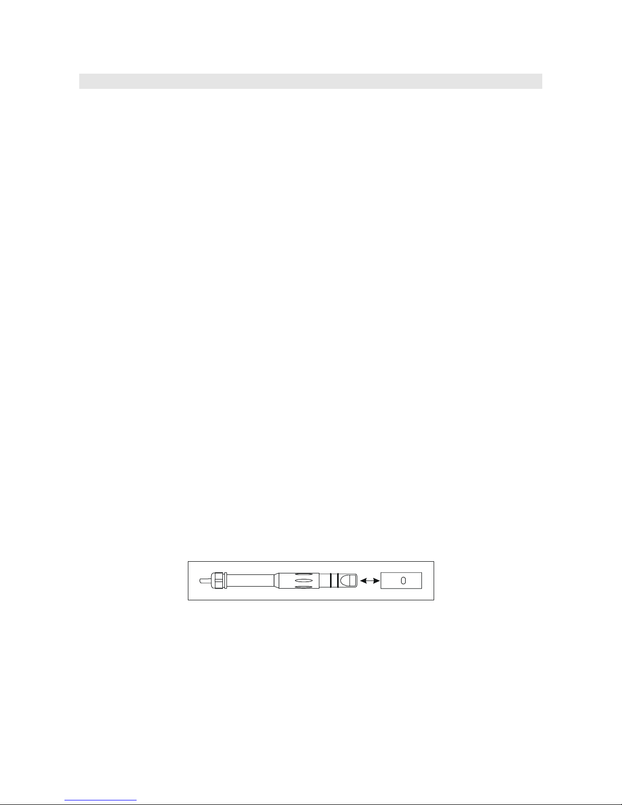
Standard probe
The standard 4-electrode combined conductivity/temperature probe code is SP06T.
The cell measurement zone is delimited by a bell in Pocan. A positioning key, present in the probe's
end part, orients the bell correctly when the probe is introduced. For cleaning, simply pull the bell
along the probe's axis without rotating it.
It is not possible to perform measurements without this bell.
This probe's temperature measuring range is -50°C a +90°C.
4- ring or 2- ring probes
The conductivity HD3406.2 uses 4-electrode or 2-electrode probes for conductivity measurement.
The 4- ring probes are preferred to measure high conductivity solutions, either over an extended
range or in presence of pollutants. The 2- ring probes operate in a shorter measurement range but
with an accuracy comparable with the 4- ring probes.
The probes can be in glass or plastic: the first can work in presence of aggressive pollutants, the lat-
ter are more resistant to collisions, and so more suitable for industrial use.

- -
14
Cells with temperature sensor
All probes are fitted with a built-in Pt100 or Pt1000 temperature sensor: the simultaneous measure-
ment of conductivity and temperature allows automatic correction of the effect of the latter on the
solution conductivity.
Choosing the cell constant
The constant is a piece of information which characterizes the cell. It depends on its geometry and
is expressed in cm–1. There is no cell capable of measuring the entire conductivity scale accurately
enough. Consequently, cells with different constants are used allowing exact measurements on dif-
ferent scales. The cell with constant K = 1cm–1 allows measurements from low conductivity up to
relatively high conductivity.
The theoretical measurement cell is made of two 1cm2metallic plates separated one from the other
by 1cm. This type of cell has a cell constant Kcell of 1cm–1. In essence, the number, form, material
and dimensions of the plates are very different from model to model, from manufacturer to manu-
facturer.
The low constant K probes are preferably used for low conductivity values, the high constant ones
for high values.
The indicative measurement range is reported in the following diagram:
Automatic or manual conductivity compensation
The conductivity measurement refers to a standard temperature, called reference temperature
T_REF: that is, the instrument proposes the conductivity you would get if the temperature were
T_REF. This temperature could be 20°C or 25°C according to the setting in the T_REF menu item.
The conductivity increase per each grade of temperature variation is a characteristic of the solution
and is indicated by the term "temperature coefficient αT": admissible values from 0.00 to 4.00%/°C,
default value 2.00%/°C.
When a combined probe with temperature sensor is present, the instrument automatically applies
the temperature compensation function, and proposes the measurement using the reference tempera-
ture T_REF according to the coefficient αTon the display.
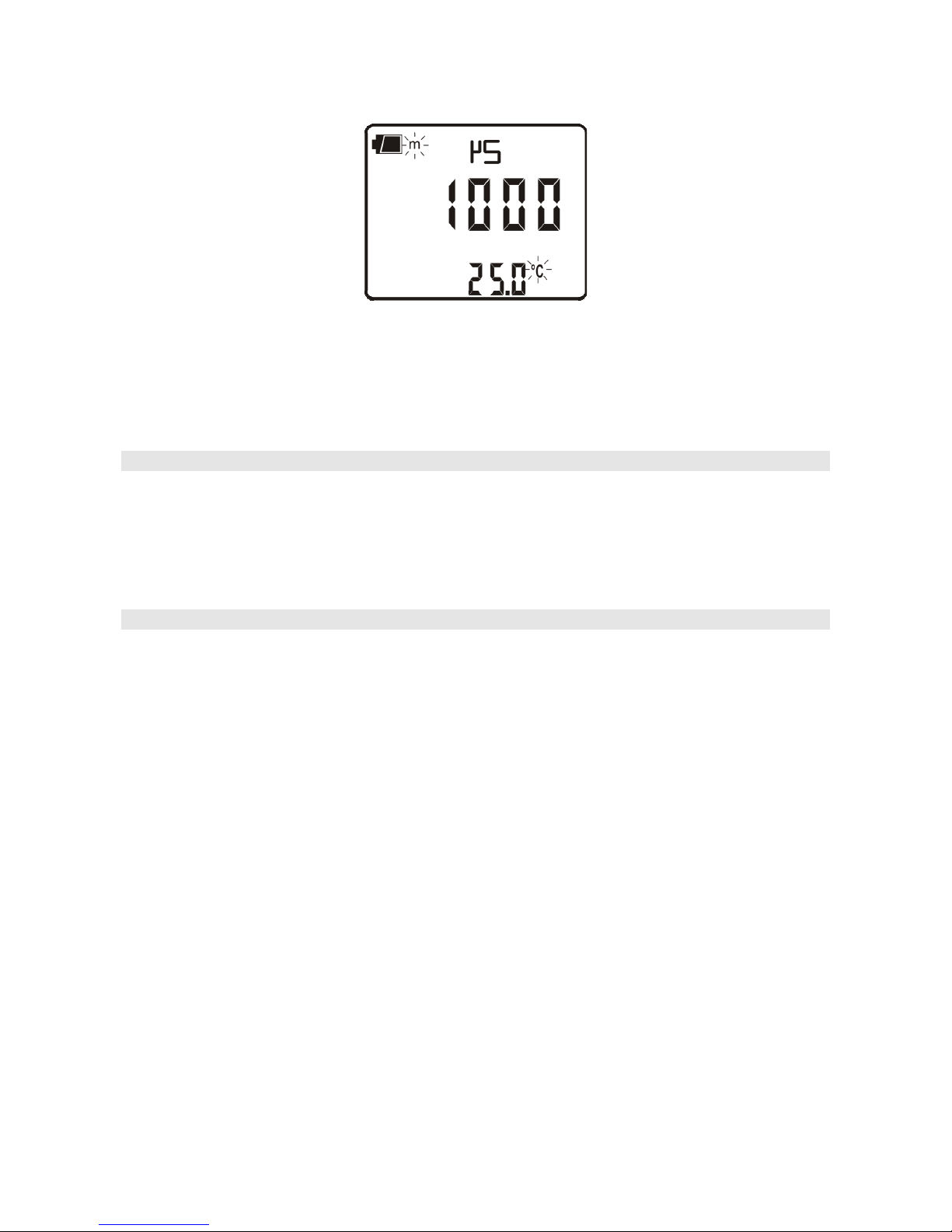
In absence of the temperature probe, the lower display shows the manually set compensation tem-
perature (default=25°C).
To point this condition out, the °C or °F symbol blinks intermittently near the temperature value.
On the main display an "m" (manual) is turned on near the battery symbol (if on). The MT indica-
tion is printed on the print-outs. On the other hand, if the temperature probe is present, the AT sym-
bol appears.
- -
15
To manually change the compensation temperature press the °C/°F key once: the indicated tempera-
ture value starts blinking. Select the desired temperature value by using the arrows and confirm with
ENTER. The display stops blinking, and the temperature displayed is used for compensation.
To change the unit of measurement between °C and °F, press the °C/°F key twice.
Calibration of conductivity
The probe calibration can be carried out on one, two or three points using the standard solutions
automatically detected by the instrument (automatic calibration) or other solutions with known
value (manual calibration).
The CAL symbol will blink when the cell constant is modified using the menu (please see the de-
scription of the K_CELL menu item on page 6).
Automatic calibration of conductivity using memorized standard solutions
The instrument can recognize four standard calibration solutions:
•0.001 Molar KCl solution (147μS/cm @25°C),
•0.01 Molar KCl solution (1413μS/cm @25°C),
•0.1 Molar KCl solution (12880μS/cm @25°C),
•1 Molar KCl solution (111800μS/cm @25°C),
Using one of these solutions, the calibration is automatic; the procedure can be repeated with one or
more of the remaining standard solutions.
The manual calibration is possible with a different conductivity solution from that used in the auto-
matic calibration.
The solution temperature for the automatic calibration must be between 15°C and 35°C: if
the solution temperature is under 15°C or over 35°C, the calibration is rejected: CAL ERR
indication appears.
1. Turn the instrument on with the ON/OFF key.
2. Set the probe's cell constant by selecting it from the admitted values: 0.01, 0.1, 0.7, 1.0 o 10.0.
3. Dip the conductivity meter cell in the calibration solution until the electrodes are covered with
liquid.
4. Stir the probe lightly to remove any possible air inside the measurement cell.
5. Press the CAL key. The unit of measurement (μS/cm or mS/cm) appears on the comment line.
The central line shows the solution conductivity value at the measured temperature, or if the

- -
16
probe is not present, at the manually-set temperature. In the lower line, the closest temperature
compensated standard buffer value.
6. Press the CAL key. The unit of measurement (μS/cm or mS/cm) appears on the comment line.
The central line shows the solution conductivity value at the measured temperature, or if the
probe is not present, at the manually-set temperature. In the lower line, the closest temperature
compensated standard buffer value.
If the measurement is in TDS, resistivity or salinity, by pressing CAL, the instrument goes
automatically into conductivity calibration mode.
7. Press ENTER to confirm the displayed value. The cell constant nominal value (KCELL) and the
set temperature coefficient αTare displayed. Pressed repeatedly the ENTER key allows the cali-
bration on the point to be repeated, for example, in order to obtain a more stable value.
8. To end the probe calibration, press ESC.
9. Rinse the probe with water. If you are then going to perform low conductivity measurements, we
recommend rinsing the probe using distilled or bidistilled water.
The instrument is calibrated and ready for use.
Manual calibration of conductivity using non memorized standard solutions
Manual calibration is possible at any calibration solution and temperature if it is within the instru-
ment measurement limits and provided that you know the solution's conductivity at the temperature
at which the calibration is performed. Proceed as follows:
1. Turn the instrument on with the ON/OFF key.
2. Set the probe's cell constant by selecting it from the admitted values: 0.01, 0.1, 0.7, 1.0 or 10.0
3. Dip the conductivity meter cell into a known conductivity solution until the electrodes are cov-
ered with liquid.
4. Stir the probe lightly to remove any possible air inside the measurement cell.
5. Press MENU, and then FUNC/ENTER until the item ALPH appears. The temperature coeffi-
cient αTis displayed. Note down the value displayed as it must be set again at the end of the
procedure. Set the value to 0.00. This excludes the temperature compensation during the con-
ductivity measurement.
6. Measure the temperature by pressing °C/°F. According to the temperature detected, determine
the calibration solution conductivity using the table specifying the conductivity according to
temperature.
7. Select the conductivity measurement by pressing χ-Ω-TDS.
8. Press the CAL key. The CAL symbol is turned on. The unit of measurement (μS/cm or
mS/cm) appears on the comment line. If the calibration solution conductivity is sufficiently
close (-30% to +50%) to one of the standard solutions, the secondary line displays the value.
Otherwise it displays the calculated value according to current settings. In the central line the
solution conductivity value is indicated according to the cell constant current settings.
9. Use the arrows to select the conductivity value determined at point 4 and confirm using EN-
TER. If the ERR indication appears, see the note below.

- -
17
10. The cell constant nominal value (KCELL) and the temperature coefficient αTset to 0 are dis-
played. Pressed repeatedly the ENTER key allows the calibration on the point to be repeated,
for example, in order to obtain a more stable value.
11. To end the probe calibration, press ESC.
12. Go back to the MENU and select ALPH: re-enter the temperature coefficient as it was before
the calibration.
13. Rinse the probe with water. If you are then going to perform low conductivity measurements,
we recommend rinsing the probe using distilled or bidistilled water.
The instrument is now calibrated and ready for use.
NOTES:
•Without having pressed ENTER at all, the calibration is interrupted by pressing ESC; the
previous values will continue to be used.
•Upon confirming the calibration by using ENTER, the instrument checks that the correction to
the conductivity does not exceed the 70% or 150% limits of the theoretical value. If the calibra-
tion is rejected because it is considered to be excessively corrupted, the CAL ERR message will
appear, followed by a long beep. The instrument remains in calibration mode and maintains the
previous calibration values.
•The most frequent causes of error are due to the probe malfunctioning (deposits, dirt,…) or to the
standard solutions deterioration (bad preservation conditions, alteration due to pollution with dif-
ferent conductivity solutions,…).
•If the measurement is in TDS, resistivity or salinity, on the pressing of CAL, the instrument goes
automatically in conductivity calibration.
Table of standard solutions at 147μS/cm, 1413μS/cm, 12.88mS/cm and 111.8mS/cm
The table reports the standard solutions automatically detected by the instrument according to tem-
perature.
°C µS/cm µS/cm mS/cm mS/cm °C µS/cm µS/cm mS/cm mS/cm
15.0 121 1147
10.48 92.5 26.0 150 1440 13.13 113.8
16.0 124 1173 10.72 94.4 27.0 153 1467 13.37 115.7
17.0 126 1199 10.95 96.3 28.0 157 1494 13.62 117.7
18.0 128 1225 11.19 98.2 29.0 161 1521 13.87 119.8
19.0 130 1251 11.43 100.1 30.0 164 1548 14.12 121.9
20.0 133 1278 11.67 102.1 31.0 168 1581 14.37 124.0
21.0 136 1305 11.91 104.0 32.0 172 1609 14.62 126.1
22.0 138 1332 12.15 105.9 33.0 177 1638 14.88 128.3
23.0 141 1359 12.39 107.9 34.0 181 1667 15.13 130.5
24.0 144 1386 12.64 109.8 35.0 186 1696 15.39 132.8
25.0 147 1413 12.88 111.8
- -
18
DIRECT INPUT INTO Pt100 AND Pt1000 TEMPERATURE PROBE WITH TP47 MODULE
The instrument accepts the input of Platinum temperature probes with resistances of 100Ωand
1000Ω.
The Pt100 are connected to 4 wires, the Pt1000 to 2 wires, with the excitation current chosen mini-
mizing the sensor self-heating effects.
The 4 wire and 2 wire probes with direct input are checked for conformity with class A toler-
ance according to norm IEC751 - BS1904 - DIN43760.
The temperature probes are automatically detected by the instrument (please see the description of
the Probe Type menu on page 8).
The °C or °F unit of measurement can be chosen for display, printing, and logging using the °C/°F
key.
How to measure
The temperature measurement by immersion is carried out by inserting the probe in the liquid for at
least 60mm; the sensor is housed in the end part of the probe.
In the temperature measurement by penetration the probe tip must be inserted to a depth of at least
60mm, the sensor is housed in the end part of the probe. When measuring the temperature on frozen
blocks it is convenient to use a mechanical tool to bore a cavity in which to insert the tip probe.
In order to perform a correct contact measurement, the measurement surface must be even and
smooth, and the probe must be perpendicular to the measurement plane.
So as to obtain the correct measurement, the insertion of a drop of oil or heat-conductive
paste is useful (do not use water or solvents). This method also improves the response time.
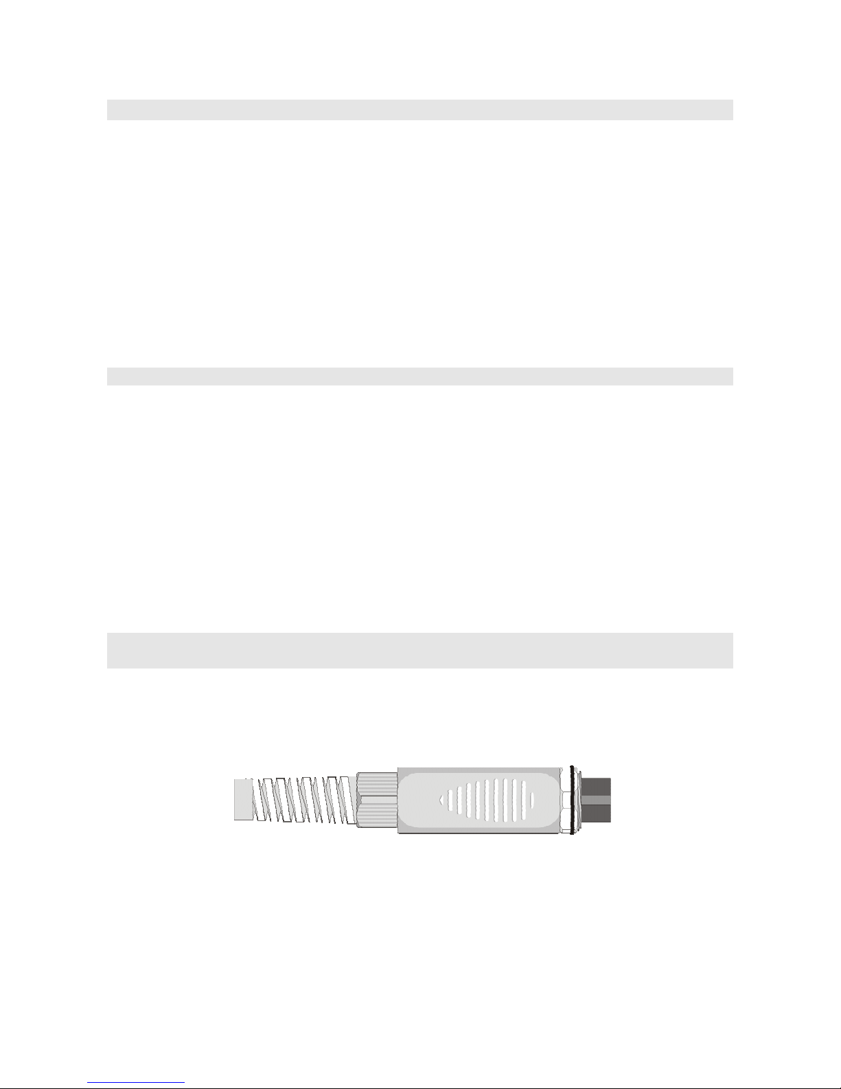
Instructions to connect the TP47 module for conductivity/temperature combined probes, 4
wire Pt100 probes and 2 wire Pt1000 probes
All Delta Ohm probes are provided with a module TP47. The HD3406.2 also work with conductiv-
ity/temperature combined probes, direct 4 wire Pt100 probes, 2 wire Pt1000 probes manufactured
by other producers: for the instrument connection is prescribed the TP47 connector to which the
probe's wires should be welded.
Instructions to connect the probe to the module are provided below.
The module is supplied complete with fairlead and gasket for 5mm maximum diameter cables.
- -
19
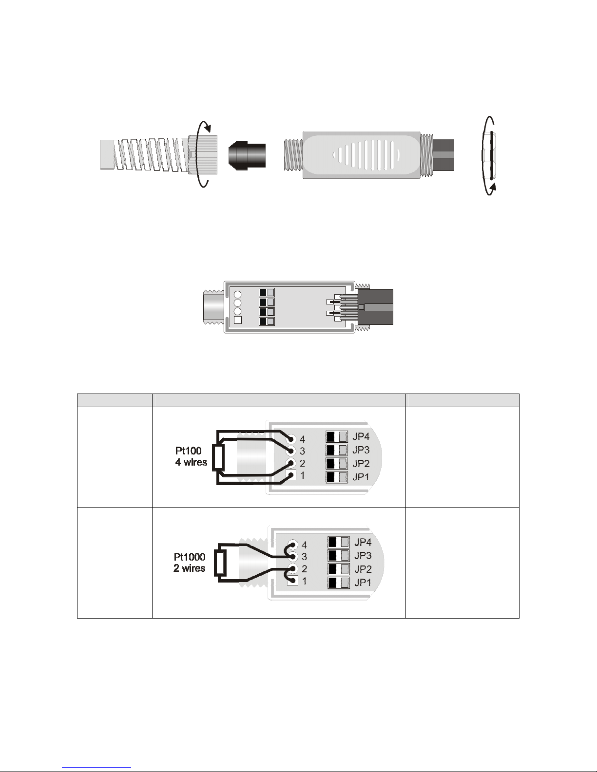
Do the following to open the module and connect a probe:
unscrew the fairlead and extract the gasket, remove the label using a cutter, unscrew the ring on the
opposite side as illustrated in the figure:
Open the two module shells: the printed circuit to which the temperature probe must be connected is
housed inside. The wires coming from the conductivity cell are welded directly onto the 1 - 2 - 4 - 5
connector's pins.
On the left there are the 1…4 points on which the Pt100 or Pt1000 sensor wires must be welded.
The JP1…JP4 jumpers are in the center of the card. These must be left open:
1
2
3
4
Pt100 3 fili
Pt1000
Ni1000
Not Used
Before welding, pass the probe cable through the fairlead and gasket.
Weld the temperature sensor wires as shown in the table:
Sensor TP47 card connection Jumper
Pt100 4 wires
None
Pt1000 2 wires
None
- -
20
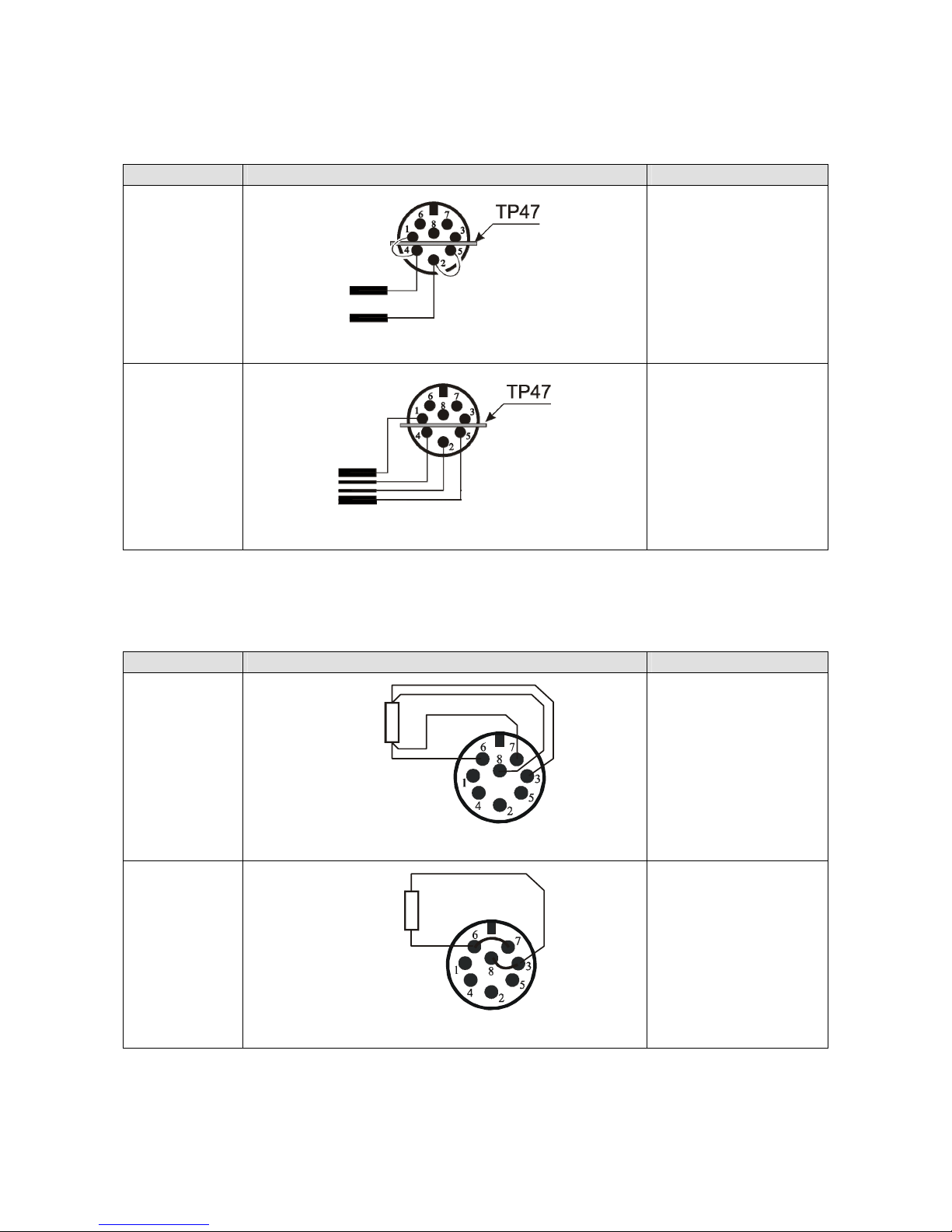
The wires coming from the conductivity probe are welded directly on the DIN45326 connector as
reported in the following table:
Sensor Direct connection to the connector Jumper
2-electrode
conductivity
probe
Internal view of the connector
Jumper between
pins 1 and 4
Jumper between
pins 2 and 5
4-electrode
conductivity
probe
Internal view of the connector
None
As an alternative, the Pt100 and Pt1000 sensors can be welded directly on the connector's pins
DIN45326, as reported in the following table:
Sensor Direct connection to the connector Jumper
Pt100 4 wires
Pt100
Internal view of the connector
None
Pt1000 2 wires
Pt1000
Internal view of the connector
Jumper between
pins 6 and 7
Jumper between
pins 3 and 8
Table of contents
Other Delta OHM Thermometer manuals

Delta OHM
Delta OHM HD2108.1 User manual

Delta OHM
Delta OHM HD2107.1 User manual

Delta OHM
Delta OHM HD2328 User manual

Delta OHM
Delta OHM HD2178.1 User manual

Delta OHM
Delta OHM HD 9212 User manual

Delta OHM
Delta OHM HD2304.0 User manual

Delta OHM
Delta OHM HD2205.2 User manual

Delta OHM
Delta OHM HD2127.1 User manual

Delta OHM
Delta OHM HD2307.0 User manual


 operating instructions")


