Delta OHM HD 9212 User manual

HD 9212
INSTRUCTIONS MANUAL

– 15 –
HD 9212
ENGLISH
pHMETER THERMOMETER
GENERAL CHARACTERISTICS
The instrument allows measurements of pH, mV or temperature to be ta-
ken with a passive 4-wire Pt100 probe of the series TP9...
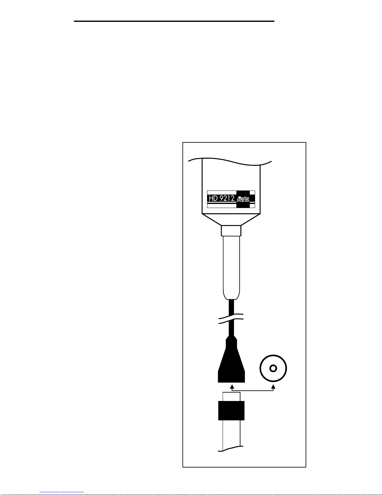
pH measurement
It is possible to take pH measurements by connecting a pH electrode to
the instrument (Fig. 1).
While measuring pH the instrument performs temperature compensa-
tion with the set temperature
value.
pH measurement is possible
in the range from -2.00 to
16.00 pH; the work range is
from 0.00 to 14.00 pH and
the value is indicated in
hundredths of pH.
If the measurement exceeds
the indicated limits or the
electrode is not connected,
the Err code appears on the
display.
mV measurement
When a pH electrode, an
electrode for measuring the
redox potential or a specific
ion electrode is connected,
the instrument performs mV
measurement (Fig. 1).
mV measurement is in the
range ±1999 mV. The mV
resolution of the instrument is
0.1 mV in the range ±199.9
mV and 1 mV in the remain-
ing range.
If the measurement exceeds
the indicated limits or the
electrode is not connected,
the Err code appears on the
display.
ENGLISH
– 16 –
EURO S7 CAP
Fig. 1
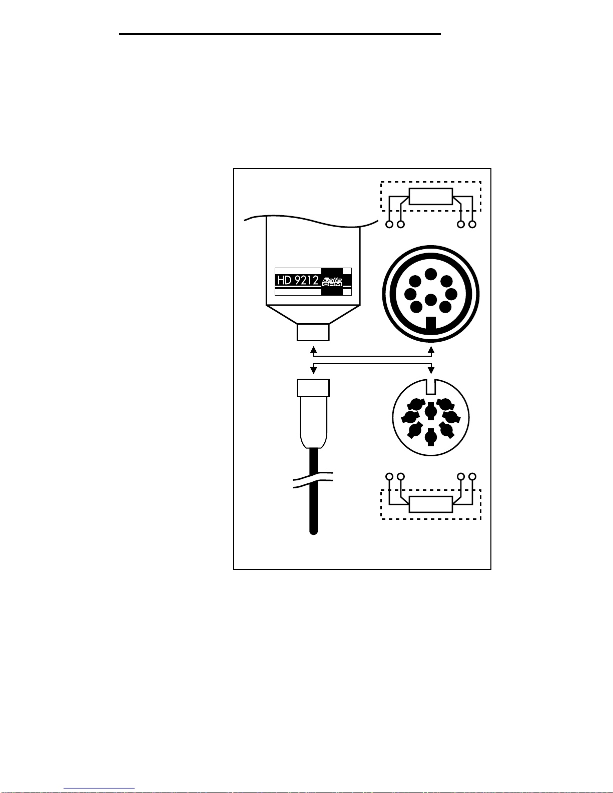
Temperature measurement
Temperature measurements may be taken by connecting to the instru-
ment a 4-wire Pt100 probe of the series TP9... (Fig. 2).
Temperature measurement is possible in the range from -50.0°C to
-199.9°C. The resolution of the instrument is 0.1°C.
The temperature
may be displayed
in either Centi-
grade or Fahren-
heit degrees.
If no temperature
probe is fitted
(and the pH or
mV probe is fit-
ted), the compen-
sation tempera-
ture of the pH
electrode is dis-
played, the set-
ting of which is
described below.
If the temperature
measurement
exceeds the indi-
cated limits or the
electrode is not
connected, and
there is no pH or
mV probe con-
nected, the Err
code appears on
the display.
Switching the instrument on and off
The instrument is switched on and off by pressing the On/Off button.
While switching on the instrument, all the symbols light up on the dis-
play for 2 seconds (test display), and the set calibration code of the
instrument (with the messages C01, C02 or C03), used for measure-
ment, and the pH measurement value are shown.
Auto power off
The instrument is provided with an auto power off function which switch-
es it off 8 minutes after the last button has been pressed.
ENGLISH
– 17 –
Temperature
probe
67 38
Pt100
61
4
7
3
58
2
7
3
5
61
4
8
2
3867
Pt100
Fig. 2

Disabling auto power off
The auto power off function is disabled during switching on of the instru-
ment, by pressing simultaneously, for at least 1 second, the On/Off and
°C/°F buttons.
When the auto power off function is disabled the battery symbol flashes.
Instrument calibration code
The instrument can operate with 3 calibration or work codes (calibration
codes). These three codes are:
• C01 calibration code set in the factory, cannot be changed
• C02 calibration code for the instrument, may be changed
• C03 calibration code for the instrument plus probe, may be
changed
When the instrument is switched on, for 2 seconds it shows the previ-
ously set work code on the display with the messages C01, C02 or C03.
Changing the work code (instrument calibration code) to be used
1. Switch on the instrument, holding down the On/Off and CAL buttons
simultaneously for at least 1 second.
During this phase the auto power off function is automatically dis-
abled (the battery symbol flashes).
After performing test display, the instrument shows the CAL mes-
sage and, after a few moments, C01, C02 or C03 (depending on the
work code used previously) with the message C flashing.
2. Using the
s
and
t
buttons, select the work code that you intend to
use, C01, C02 or C03.
3. Confirm the work code by pressing the CAL button. The instrument
switches off, after having displayed the CAL message.
If you have selected a work code different from those available, the
instrument switches off but the previously set work code is not
changed.
4. Switch the instrument on again and check that the desired work code
is used.
Displaying measurements in pH or in mV
By pressing the pH/mV button it is possible to display the measurement
taken at the instrument input in pH or mV units.
The unit in which the value is measured is indicated on the display.
When switched on, the instrument is set for pH measurement.
ENGLISH
– 18 –

Displaying temperature and changing the measuring unit
By pressing the °C/°F button it is possible to display the temperature
measured (if a 4-wire Pt100 temperature probe of the series TP9... is
connected) or the pH electrode compensation temperature (if a pH elec-
trode is connected).
By pressing the °C/°F button repeatedly it is possible to display the tem-
perature in °C or in °F.
The unit chosen for measuring the temperature value is indicated on the
display.
Temperature compensation of the pH electrode
The instrument performs temperature compensation of the pH electrode
with the set temperature value.
Before measuring the pH, store the temperature of the solution to be
examined, measuring it with the 4-wire Pt100 temperature probe of the
series TP9.
The value measured and shown on the display is stored by pressing the
CAL button (the instrument shows the CAL message for a brief
moment).
On disconnecting the temperature probe and connecting the pH elec-
trode, the instrument uses the previously stored temperature value to
calculate the temperature compensation of the pH measurement.
The temperature value used for temperature compensation may be
changed at will even while taking the pH measurement. To this, pro-
ceed as follows:
1. display the compensation temperature in °C by pressing the °C/°F
button;
2. press the CAL button to enable modification of the temperature value
(the °C symbol flashes);
3. set the desired temperature value with the
s
and
t
buttons;
4. press the CAL button again to confirm and store the value, the
instrument shows the CAL message for a moment, and the °C
symbol stops flashing.
Calibration of the pH electrode
The pH electrode must be calibrated from time to time to correct losses
in efficiency of the electrode.
The instrument recognizes three calibration buffer solutions: pH 6.86 for
calibrating the offset of the electrode, and pH 4.01 or pH 9.18 for cali-
brating amplification, in a basic and acid environment respectively.
The instrument does not make automatically the compensation temper-
ENGLISH
– 19 –

ature with respect to the buffer value. The compensation must be done
manually.
Before calibrating the electrode, the compensation value of the pH elec-
trode must be set in the instrument; this is equal to the temperature
value of the buffer solutions used, and is set with a temperature probe
or directly with the
s
and
t
buttons (see the description in the previous
paragraph).
Calibration of the offset
1. Connect a pH electrode to the input of the instrument; insert the
electrode in the buffer solution at pH 6.86.
Stir the electrode in the solution so as to eliminate any air bubbles
and wait until the measurement has become stable.
2. When the measurement is stable press the CAL button.
The symbol indicating pH flashes and the display shows the desired
pH value.
3. By pressing the
s
and
t
buttons it is possible to change the pH
value until it coincides with the value of the buffer solution used, at
the set temperature for calibration of the electrode.
4. When CAL is pressed the instrument quits calibration of the offset of
the electrode and the pH symbol stops flashing. The instrument
shows the CAL message for a moment.
At this point the instrument shows a value equal to that of the buffer
solution used, at the set temperature.
Calibration of amplification
1. Insert the pH electrode in the buffer solution at pH 4.01 or pH 9.18.
Stir the electrode in the solution so as to eliminate any air bubbles.
2. When the measurement is stable press the CAL button.
The symbol indicating pH flashes and the display shows the desired
pH value, depending on the buffer solution used.
3. By pressing the
s
and
t
buttons it is possible to change the pH
value until it coincides with the value of the buffer solution used, at
the set temperature for calibration of the electrode.
4. When CAL is pressed the instrument quits calibration of amplifica-
tion. The pH symbol stops flashing. The instrument shows the CAL
message for a few moments.
At this point the instrument shows a value equal to that of the buffer
solution used, at the set temperature.
This completes calibration of the pH electrode.
ENGLISH
– 20 –
PROCEDURE FOR CALIBRATING THE INSTRUMENT
(WORK CODE C02)
Selecting the work code for calibrating the instrument
1. Switch on the instrument, holding down the On/Off and CAL buttons
simultaneously for at least 1 second.
During this
phase the auto
power off func-
tion is automati-
cally disabled
(the battery
symbol flashes).
The instrument
shows the CAL
message and,
after a few
moments, C01,
C02 or C03
(depending on
the work code
used previously)
with the mes-
sage C flashing.
2. Using the
s
and
t
buttons,
select the work
code C06.
3. Confirm the
work code by
pressing the
CAL button. The
instrument dis-
plays the work
code C02 for a
few moments.
The voltage input must be calibrated first, then the temperature
input.
Using the pH/mV button, select mV measurement to calibrate the
voltage input. First calibrate the offset (0.0 mV), the first calibration
point, and then amplification (480 mV), the second calibration point.
ENGLISH
– 21 –
61
4
7
3
58
2
34
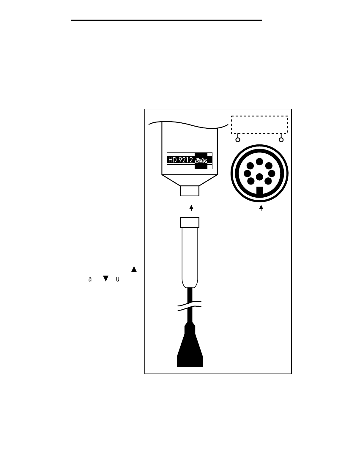
Tension simulator
OUT GND
Fig. 3

First voltage calibration point
1. Connect a voltage simulator to the input of the instrument (Fig. 3);
simulate a value of 0.0 mV, that is the first calibration point.
2. When the measurement is stable press the CAL button.
The symbol indicating mV flashes and the display shows the value
0.0°C.
3. By pressing the
s
and
t
buttons it is possible to change the mV
value until it coincides with the value of the simulator (in this case a
value different from 0.0 mV must be simulated).
4. When CAL is pressed again the instrument quits calibration of the
first calibration point. The mV symbol stops flashing. The instrument
shows the CAL message for a few moments.
At this point the indication on the instrument coincides with that set
on the simulator.
Second voltage calibration point
1. At input of the instrument, simulate the second calibration point, 480
mV, or a value less than 490 mV.
2. When the measurement is stable press the CAL button.
The symbol indicating mV flashes and the display shows the value
480 mV.
3. By pressing the
s
and
t
buttons it is possible to change the mV
value until it coincides with the value of the simulator (in this case a
value different from 480 mV must be simulated).
4. When CAL is pressed again the instrument quits calibration of the
second calibration point. The mV symbol stops flashing. The instru-
ment shows the CAL message for a few moments.
At this point the indication on the instrument coincides with that set
on the simulator.
This concludes voltage calibration of the input.
By selecting display in °C it is possible to calibrate the temperature
of the instrument. First calibrate the offset (0.0°C), the first calibration
point, and then amplification (197.0°C), the second calibration point.
ENGLISH
– 22 –

First temperature calibration point
1. Connect a 4-wire Pt100 simulator to the input of the instrument
(Fig. 4); simulate a value of 0.0°C, that is the first calibration point.
2. When the measurement is stable press the CAL button.
The symbol indicating °C flashes and the display shows the value
0.0°C.
3. By pressing the
s
and
t
buttons it is possible to change the °C
value until it
coincides with
the value of the
simulator (in this
case a value dif-
ferent from
0.0°C must be
simulated).
4. When CAL is
pressed again
the instrument
quits calibration
of the first cali-
bration point.
The °C symbol
stops flashing.
The instrument
shows the CAL
message for a
few moments.
At this point the
indication on the
instrument coin-
cides with that
set on the simu-
lator.
Second temperature calibration point
1. At input of the instrument, simulate the second calibration point,
197.0°C, or a value less than 199.9°C.
2. When the measurement is stable press the CAL button.
The symbol indicating °C flashes and the display shows the value
197.0°C.
3. By pressing the
s
and
t
buttons it is possible to change the °C
value until it coincides with the value of the simulator (in this case a
value different from 197.0°C must be simulated).
ENGLISH
– 23 –
Temperature
probe
61
4
7
3
58
2
3867
Pt100
simulator
Fig. 4

4. When CAL is pressed again the instrument quits calibration of the
first calibration point.
The °C symbol stops flashing and the auto power off function is
restored (the battery symbol stops flashing). The instrument shows
the CAL message for a few moments.
At this point the indication on the instrument coincides with that set
on the simulator.
This completes calibration of the instrument and the calibration values are
stored in the work code C02.
PROCEDURE FOR CALIBRATING THE INSTRUMENT
AND ITS PROBE IN VOLTAGE OR THE PASSIVE 4-WIRE
PT100 TEMPERATURE PROBE (WORK CODE C03)
Selecting the work code for calibrating the instrument
1. Switch on the instrument, holding down the On/Off and CAL buttons
simultaneously for at least 1 second.
During this phase the auto power off function is automatically
disabled (the battery symbol flashes).
The instrument shows the CAL message and, after a few moments,
C01, C02 or C03 (depending on the work code used previously) with
the message C flashing.
2. Using the
s
and
t
buttons, select the work code C08.
3. Confirm the work code by pressing the CAL button. The instrument
displays the work code C03 for a few moments.
The voltage input must be calibrated first, then the temperature
input.
By selecting mV display it is possible to calibrate the voltage input of
the instrument plus the probe. First calibrate the offset (0.0 mV), the
first calibration point, and then amplification (480 mV), the second
calibration point.
First voltage calibration point
1. The voltage probe chosen for the combination is connected to the
instrument (Fig. 1). The probe will be immersed in the chosen buffer
solution. The simulated voltage will be, for example, 0.0 mV, that is
the first calibration point.
2. When the measurement is stable press the CAL button.
The symbol indicating mV flashes and the display shows the value
0.0 mV.
ENGLISH
– 24 –

3. By pressing the
s
and
t
buttons it is possible to change the mV
value until it coincides with the reference value.
4. When CAL is pressed again the instrument quits calibration of the
first calibration point. The mV symbol stops flashing. The instrument
shows the CAL message for a few moments.
At this point the indication on the instrument coincides with the value
of the reference buffer solution.
Second voltage calibration point
1. Insert the probe in the buffer solution with a voltage corresponding to
the second calibration point, 480 mV, or a value less than 490 mV.
2. When the measurement is stable press the CAL button.
The symbol indicating mV flashes and the display shows the value
480°C.
3. By pressing the
s
and
t
buttons it is possible to change the mV
value until it coincides with the reference value.
4. When CAL is pressed again the instrument quits calibration of the
second calibration point. The mV symbol stops flashing. The instru-
ment shows the CAL message for a few moments.
At this point the indication on the instrument coincides with the value
of the reference buffer solution.
By selecting display in °C it is possible to calibrate the tempera-
ture of the instrument plus the probe. First calibrate the offset
(0.0°C), the first calibration point, and then amplification
(197.0°C), the second calibration point.
First temperature calibration point
1. The passive 4-wire Pt100 probe chosen for the combination is con-
nected to the instrument (Fig. 2) and will be inserted in a calibrating
furnace; the temperature of the furnace will be, for example, 0.0°C,
corresponding to the first calibration point.
2. When the measurement is stable press the CAL button.
The symbol indicating °C flashes and the display shows the value
0.0°C.
3. By pressing the
s
and
t
buttons it is possible to change the °C
value until it coincides with the value of the reference probe in the
calibration furnace.
4. When CAL is pressed again the instrument quits calibration of the
first calibration point. The °C symbol stops flashing. The instrument
shows the CAL message for a few moments.
At this point the indication on the instrument coincides with the value
of the probe in the calibration furnace.
ENGLISH
– 25 –

Second calibration point
1. Insert the probe in a furnace with a temperature corresponding to the
second calibration point, for example 197.0°C, or a value less than
199.9°C.
2. When the measurement is stable press the CAL button.
The symbol indicating °C flashes and the display shows the value
197.0°C.
3. By pressing the
s
and
t
buttons it is possible to change the °C
value until it coincides with the value of the reference probe in the
calibration furnace.
4. When CAL is pressed again the instrument quits calibration of the
first calibration point. The °C symbol stops flashing and the auto
power off function is restored (the battery symbol stops flashing).
The instrument shows the CAL message for a few moments.
At this point the indication on the instrument coincides with the value
of the probe in the calibration furnace.
This completes calibration of the instrument and its probe and the calibra-
tion values are stored in the work code C03.
NOTE: Once the instrument has been calibrated with its probes, the same
probes must be used to obtain correct measurements.
ERRORS AND DISPLAY
Measuring error
If the probe to be used for the measurement selected is not corrected or
is in error status (faulty probe or measurement out of the range that can
be represented), the Err message is displayed.
Low battery voltage
If the battery voltage is low the battery symbol remains lit, informing the
user that it is time to change the battery. The auto power off disable
function is cancelled.
Battery voltage too low
If the battery voltage falls even further, below a minimum threshold for
operation, the battery symbol remains lit, the instrument displays the
message LOU and then it switches off after 1 second. The battery must
therefore be changed before the instrument can be used again.
ENGLISH
– 26 –

Reading and writing error of sets of instrument calibration parameters
If errors occur in the reading or writing of the sets of parameters for cali-
brating the instrument, the Er1 code is shown alternately with the mea-
surement. In this case it is necessary to switch the instrument off and
on again, if the signal is repeated, calibration must be repeated.
If the error persists, send the instrument to the manufacturer for repairs.
In the event of error in reading the parameters, the instrument can ope-
rate temporarily with the default values.
ENGLISH
– 27 –

GUARANTEE CONDITIONS
All our appliances have been subjected to strict tests and are guaranteed for 24 months from date of pur-
chase. The Company undertakes to repair or replace free of charge any parts which it considers to be inef-
ficient within the guarantee period. Complete replacement of the instrument is excluded and no requests
for damages are recognized, whatever their origin. Repairs are carried out in our own Technical Service
Department. Transport expenses are borne by the buyer. The guarantee does not include: accidental
breakages due to transport, incorrect use or neglect, incorrect connection to voltage different from
that contemplated for the instrument, probes, sensors, electrodes and all accessories. Furthermore
the guarantee is not valid if the instrument has been repaired or tampered with by unauthorized third par-
ties, or adjusted for faults or casual checking. The guarantee is valid only if all parts of the guarantee card
have been filled in. Any instruments sent for repairs must be accompanied by their guarantee certificate.
For all disputes the competent court is the Court of Padua.
ENGLISH
– 28 –

DELTA OHM SRL
VIA G. MARCONI, 5 - 35030 CASELLE DI SELVAZZANO (PD) - ITALY
TEL. 0039-0498977150 r.a. - FAX 0039-049635596
SIT CALIBRATION
CENTRE N° 124
CE CONFORMITY
Safety EN61000-4-2, EN61010-1 level 3
Electrostatic
discharge EN61000-4-2 level 3
Electric fast
transients EN61000-4-4 level 3
Voltage variations EN61000-4-11
Electromagnetic
interference IEC1000-4-3
sucseptibility
Electromagnetic
interference EN55020 class B
emission
Table of contents
Other Delta OHM Thermometer manuals

Delta OHM
Delta OHM HD2304.0 User manual

Delta OHM
Delta OHM HD2328 User manual

Delta OHM
Delta OHM HD2127.1 User manual

Delta OHM
Delta OHM HD2178.1 User manual

Delta OHM
Delta OHM HD2107.1 User manual

Delta OHM
Delta OHM HD2307.0 User manual

Delta OHM
Delta OHM HD2205.2 User manual

Delta OHM
Delta OHM HD3406.2 User manual

Delta OHM
Delta OHM HD2108.1 User manual


