Delta OHM HD2304.0 User manual

Our instruments' quality level is the results of the product continuous development. This
can bring about differences between the information written in this manual and the
instrument that you have purchased. We cannot entirely exclude errors in the manual, for
which we apologize.
The data, figures and descriptions contained in this manual cannot be legally asserted. We
reserve the right to make changes and corrections without prior notice.
HD2304.0
MANOMETER –THERMOMETER
ENGLISH
REV. 1.6
July 2nd 2014

- -
2
Manometer - Thermometer
HD2304.0

- -
3
HD2304.0
1. Input for probes, 8-pole DIN45326 connector.
2. Battery symbol: displays the battery charge level.
3. Function indicators.
4. Secondary display line.
5. DATA/ENTER key: during normal operation displays the maximum (MAX), the minimum
(MIN) and the average (AVG) of current measurements; in the menu, confirms the current
selection.
6. CLR/ESC key: during normal operation resets the maximum, the minimum and the average of
current measurements; in the menu, it resets the value set with the arrows.
7. HOLD/key: freezes the measurement during normal operation; in the menu, increases the
current value.
8. UNIT/MENU key: it allows selection of the unit of measurement; when pressed together with
the DATA key, it allows to open the menu.
9. ZERO: performs the zero function, if the connected probe is the one that measures the
differential pressure.
10. REL/key: during normal operation enables the relative measurement (displays the difference
between the current value and the logged value when the key is pressed); in the menu, decreases
the current value.
11. ON-OFF/AUTO-OFF key: turns the instrument on and off; when pressed together with the
HOLD key, disables the AutoPowerOff function.
12. MAX (maximum value), MIN (minimum value) and AVG (average value) symbols.
13. Main display line.
14. Line for symbols and comments.

- -
4
TABLE OF CONTENTS
1. GENERAL CHARACTERISTICS.............................................................................................................................5
2. DESCRIPTION OF THE FUNCTIONS ....................................................................................................................6
3. MENU............................................................................................................................................................................9
4. PROBES AND MEASUREMENTS..........................................................................................................................10
4.1 PP471 MODULE FOR PRESSURE MEASUREMENT..................................................................................................10
4.2 Pt100 TEMPERATURE PROBE...............................................................................................................................11
4.2.1 Temperature measurement .............................................................................................................................11
4.2.2 Connecting the TP47 connector .....................................................................................................................11
4.2.3 Direct connection of 4 wire Pt100 sensors.....................................................................................................13
5. WARNINGS................................................................................................................................................................14
6. INSTRUMENT SIGNALS AND FAULTS...............................................................................................................15
7. INSTRUMENT STORAGE.......................................................................................................................................16
8. LOW BATTERY WARNING AND BATTERY REPLACEMENT .....................................................................17
8.1 WARNING ABOUT BATTERY USE.........................................................................................................................17
9. NOTES ABOUT WORKING AND OPERATIVE SAFETY.................................................................................18
10. TECHNICAL CHARACTERISTICS ....................................................................................................................19
10.1 TECHNICAL INFORMATION ON THE MANOMETER –THERMOMETER................................................................19
10.2 ON LINE INSTRUMENT PROBES AND MODULES TECHNICAL DATA ....................................................................20
10.2.1 Pressure measurement by module PP471.....................................................................................................20
10.2.2 Temperature probes Pt100 using SICRAM module.....................................................................................21
10.2.3 - 4 wire Pt100 Probes ..................................................................................................................................21
11. ORDER CODES.......................................................................................................................................................22
11.1 PROBES COMPLETE WITH SICRAM MODULE ...................................................................................................22
11.2 TEMPERATURE PROBES WITHOUT SICRAM MODULE ......................................................................................22

- -
5
1. GENERAL CHARACTERISTICS
The Manometer - Thermometer Model HD2304.0 is a portable instrument that allows measurement
of absolute, relative and differential pressure, and temperature.
The PP471 electronic module is used to measure the pressure. The module works as an interface
between the instrument and the TP704 and TP705 series Delta Ohm probes.
The temperature is detected using immersion, penetration, contact or air Pt100 probes with
SICRAM module, or direct 4 wire Pt100 probes.
The probes are fitted with the SICRAM automatic detection module, with the factory calibration
settings already being memorized inside.
The units of measurement for the measurable quantities are:
Pa (Pascal)
hPa (hectopascal)
kPa (kilopascal)
mbar (millibar)
bar (bar)
atm (atmosphere)
mmHg (millimeter of mercury)
mmH2O (millimeter of water)
kgf/cm² (kilogram-force/square centimeter)
PSI
inchHg (inch of mercury)
°C/°F
Using the MAX, MIN and AVG function of this instrument respectively obtains the maximum,
minimum or average values.
Other available functions are:
the relative measurement REL;
the HOLD function;
the automatic turning off which can also be disabled.
For further details see chapter 2.

- -
6
2.DESCRIPTIONOF THE FUNCTIONS
The keyboard of the Manometer –Thermometer Model HD2304.0 is composed of double-function
keys. The function on the key is the "main function", while the one above the key is the "secondary
function".
When the instrument is in standard measurement mode, the main function is active.
Once the Settings Menu has been opened, by pressing simultaneously the DATA+UNIT keys, the
secondary function is enabled.
The pressing of a key is accompanied by a short confirmation "beep": a longer "beep" sounds if the
wrong key is pressed. Each key specific function is described in detail below.
This key has two functions:
ON/OFF: to turn the instrument on press ON, to turn it off press OFF.
The turning on enables all display segments for a few seconds, starts an Auto-test including the
detection of the probe connected to the input, and sets the instrument ready for normal
measurement. The following is displayed:
AUTO/OFF: the AutoPowerOff function can be disabled by simultaneously pressing this key
and the "HOLD" key when turning the instrument on.
During turning on, should no probes be connected, the "NO_PRBE_SER_NUM" message is
displayed in the line for symbols for a few seconds, while the "ERR" message is shown in the
central part of the display. When the probe is inserted into a functioning instrument, the
"NEW_PROB_DET" (New probe detected) message appears, while the "ERR" message is
shown in the central part of the display, and a sequence of "beeps" is simultaneously issued. As the
data are captured upon turning the instrument on, it is necessary to turn it off and on again.
Caution! Replace the probes when the instrument is off.
The instrument has an AutoPowerOff function that automatically turns the instrument off after about
8 minutes if no key is pressed during the intervening time. Press simultaneously the ON/OFF key
and the HOLD key to disable this function.
In this case, remind to turn the instrument off with the ON/OFF key: the automatic turning off
disabling is shown by the battery symbol blinking.
MIN
cm
min s
2
3
mµ
m
k
>>>
Disabling of the automatic turning off
ON/OFF and AUTO/OFF key

- -
7
The "CLR" key has two functions:
CLEAR (CLR): allows to reset the maximum (MAX), minimum (MIN) and average (AVG)
value of the captured measurements;
ESC: once the MENU has been opened with the DATA+UNIT keys, the CLR key will allow
to cancel the parameters set using the and arrows.
The "DATA" key is used for the following functions:
DATA: during normal measurement, by pressing this key once the maximum (MAX) value of
the measurements captured by the probe connected to the instrument is displayed, updating it
with the acquisition of new samples;
-by pressing this key again the minimum (MIN) value is displayed;
-by pressing this key a third time the average(AVG) value is displayed.
The acquisition frequency is once a second.
The MAX, MIN and AVG values remain in the memory until the instrument is on, even after
exiting the DATA calculation function. When the instrument is off, the previously memorized
data are cleared. Upon turning on, the instrument automatically starts memorizing the MAX,
MIN and AVG values.
To reset the previous values and start with a new measurement session, press CLR until the
FUNC_CLRD message appears.
ENTER: once the MENU has been opened with the DATA+UNIT keys, the DATA key will
perform the ENTER function and the MENU can be browsed and the displayed parameter
confirmed. During electrode calibration, it allows to decrease the nominal buffer value.
The HOLD key is used for the following functions:
HOLD: by pressing this key the current measurement is frozen and the "HOLD" message will
appear in the upper left-hand corner of the display. To return to the current measurement, press
the key again.
: once the MENU has been opened with the DATA+MENU key, the key will allow to
increase the value of the selected parameter.
Pressed together with the ON/OFF key, during turn on, the AutoPowerOff function is disabled (see
the description of the ON/OFF key).
DATA/ENTER key
CLR/ESC key
HOLD/key

- -
8
The "UNIT" key is used for the following functions:
UNIT: by pressing this key the unit of measurement of the input probe is selected: the unit of
measurement will appear in the upper part of the display; the measured value will be displayed
in the central line. By repeatedly pressing the UNIT key, the desired unit of measurement can
be selected between the following:
Pressure measurement unit:
Pa (Pascal)
hPa (hectopascal)
kPa (kilopascal)
mbar (millibar)
bar (bar)
atm (atmosphere)
mmHg (millimeter of mercury)
mmH2O (millimeter of water)
kgf/cm² (kilogram-force/square centimeter)
PSI
inchHg (inch of mercury)
Temperature measurement unit:
°C (Celsius degrees)
°F (Fahrenheit degrees)
MENU: the menu includes the Probe Type item. This item displays the type of probe
connected to the instrument's input (see chapter 3):
-the menu is opened by pressing simultaneously DATA+UNIT: the first item of the
instrument programming menu will appear;
-use the and arrows (respectively located above the HOLD and REL keys) to modify
the displayed value;
-press DATA/ENTER to confirm the modification and go onto the next item;
-press CLR/ESC to cancel the modification;
-to exit the menu, press the UNIT/MENU key again.
By pressing this key the ZERO function is performed if the connected probe is the one that
measures the differential pressure.
The "REL" key is used for the following functions:
REL: it displays the difference between the current value and that measured on pressing the
key. The "REL" message is displayed on the left. To return to the normal measurement, press
the key again.
: once the MENU has been opened with the UNIT+MENU key, the key will allow to
decrease the value of the selected parameter.
REL/key
UNIT/MENU key
ZERO key

- -
9
3.MENU
To access to the menu press simultaneously the following keys:
Menu:
Probe type: the "PRBE_TYPE" message is displayed in the comment line. The main line in the
center of the display shows the type of probe connected to the instrument. The following probes can
be connected to the input:
TP704 and TP705 pressure probes combined with the PP471 module: the type of probe (i.e.
if the PP471 module and the TP704-2BAI probe (2 bar absolute) are connected) is shown in
the central part of the display. In the main line "2" is displayed, which indicates the sensor's
bottom scale. The unit of measurement "bAr" and the sensor characteristic "Abs" (absolute)
are displayed alternately in the secondary line;
temperature probes "Pt100" complete with SICRAM module: the "Auto" message is
displayed in the central part of the display;
direct 4 wire "Pt100" temperature probes: in this case, the "100Pt_4u" message is displayed.
NOTE: Upon turning on the instrument automatically detects the probes fitted with SICRAM
module: the type of probe is configured by the instrument and cannot be modified by the user.
If direct 4 wire "Pt100" probes that are not manufactured by "Delta Ohm" are connected to the
instrument, the NO_PRBE_SER_NUM message is displayed .
-use the and arrows (respectively located above the HOLD and REL keys) to modify the
displayed value;
-press DATA/ENTER to confirm the modification and go onto the next item;
-press CLR/ESC to cancel the modification;
-to exit the menu, press the UNIT/MENU key again.

- -
10
4. PROBES AND MEASUREMENTS
The instrument measures absolute, relative and differential pressure using the PP471 SICRAM
module and the TP704 and TP705 series probes. It also measures the temperature with a Pt100
sensor fitted with SICRAM module, or with direct 4 wire Pt100 probes.
The SICRAM module acts as an interface between the sensor on the probe and the instrument.
There is a microprocessor circuit with a permanent memory inside the module that enables the
instrument to recognize the type of probe connected and to read its calibration information.
The probes are detected during turn on, and this cannot be performed when the instrument is
already on, therefore if a probe is connected and the instrument is on, it is necessary to turn it
off and on.
The probes fitted with SICRAM module are calibrated in the factory; no calibration is required by
the user.
4.1 PP471 MODULE FOR PRESSURE MEASUREMENT
The PP471 module acts as an interface between the TP704 and TP705 series Delta Ohm probes and
the instrument.
The TP704 series pressure probes have a 1/4" BSP threaded male connection, and must be screwed
into the system using the necessary sealing gaskets.
The TP705 series have two Ø5 connections where the suitable tubes are inserted in order to perform
the desired measurement.
Caution! Please pay careful attention to the joint pressure sealing; use suitable gaskets and joints.
The threaded connection is protected by a plastic cap. Put it back after use as it protects the pressure
cell from foreign bodies.
IMPORTANT! Ensure the probe's bottom scale is higher than the pressure that will be
measured. In case this value is unknown, start by using higher-capacity probes.
For every pressure probe a range of overload pressure and a burst pressure are declared:
pressures in the range of overload pressure don’t cause the break of the sensor but the
declared accuracy can be overcome. Pressure over the stated burst pressure may break the
sensor. The application of higher pressures than the overload pressure limit, although lower
than the burst pressure, may produce permanent damage to the probe (e.g. offset shift). Never
exceed the stated burst pressure.
Please see the technical characteristics of the probes on paragraph “Technical characteristics”.
Upon turning on the instrument automatically detects the PP471 module. The probe's type
(absolute, relative or differential) and bottom scale value are detected even when the instrument is
on (see chapter 3).
To change the instantaneous or peak value unit of measurement, press UNIT. The following units of
measurement are available:
Pa, hPa, kPa, mbar, bar, atm, mmHg, mmH2O, kgf/cm2, PSI, inchHg.
Some units of measurement require a degree of multiplication:
the "-3" symbol indicates the displayed value must be divided by 1,000;
the "3" and "6" symbols indicate the displayed value must be multiplied respectively by 1,000
or by 1,000,000.
The instrument does not automatically detect the probes which are not fitted with SICRAM module.

- -
11
4.2 Pt100 TEMPERATURE PROBE
The instrument accepts the input of Platinum temperature probes with resistances of 100Ω (Pt100).
The Pt100 sensors are connected to 4 wires; the excitation current was chosen in order to minimize
the sensor self-heating effects.
All probes with module are calibrated in the factory; no calibration is usually required by the user.
The °C or °F unit of measurement can be chosen using the UNIT key.
4.2.1 Temperature measurement
The response time for the measurement of the temperature in air is greatly reduced if the air is
moving. If the air is still, stir the probe. Please remember that the response times in any case are
longer than those for liquid measurements.
The temperature measurement by immersion is carried out by inserting the probe in the liquid for at
least 60 mm; the sensor is housed in the end part of the probe.
In the temperature measurement by penetration the probe tip must be inserted to a depth of at least
60 mm, the sensor is housed in the end part of the probe.
NOTE: when measuring the temperature on frozen blocks it is convenient to use a mechanical tool
to bore a cavity in which to insert the tip probe.
In order to perform a correct contact measurement, the measurement surface must be even and
smooth, and the probe must be perpendicular to the measurement plane.
So as to obtain the correct measurement, the insertion of a drop of oil or heat-conductive
paste between the surface and the probe is useful (do not use water or solvents). This method
also improves the response time.
4.2.2 Connecting the TP47 connector
All probes produced by Delta Ohm are provided with a connector.
The HD2304 also work with direct 4 wire Pt100 probes manufactured by other producers: for the
instrument connection is prescribed the TP47 connector to which the probe’s wires should be
welded.
The instructions to connect the Platinum probe to the TP47 module are provided below.
The TP47 module is supplied complete with fairlead and gasket for 5 mm maximum diameter
cables. Do the following to open the module and connect a probe:
1. unscrew the fairlead;
2. extract the gasket;
3. remove the label using a cutter;
4. unscrew the ring on the opposite side as illustrated in the figure:
- -
12
5. open the two module shells: the printed circuit to which the probe must be connected is housed
inside. On the left there are the 1…4 points on which the sensor wires must be welded. The
JP1…JP4 jumpers are in the center of the board. These must be closed with a tin bead for some
type of sensors:
1
2
3
4
Pt100 3 wires
Pt1000
Ni1000
NotUsed
Caution! Before welding, pass the probe cable through the fairlead and gasket.
6. Weld the wires as shown in the table:
Sensor
Board connection
Jumper to close
Pt100 4 wires
4JP4
3JP3
1JP1
2 JP2
Pt100
4 wires
None
Ensure the welds are clean and perfect.
7. Once the welding operation is complete, close the two shells;
8. insert the gasket in the module;
9. screw the fairlead and the ring. Make sure the cable is not twisted while you are screwing the
fairlead. Now the probe is ready.

- -
13
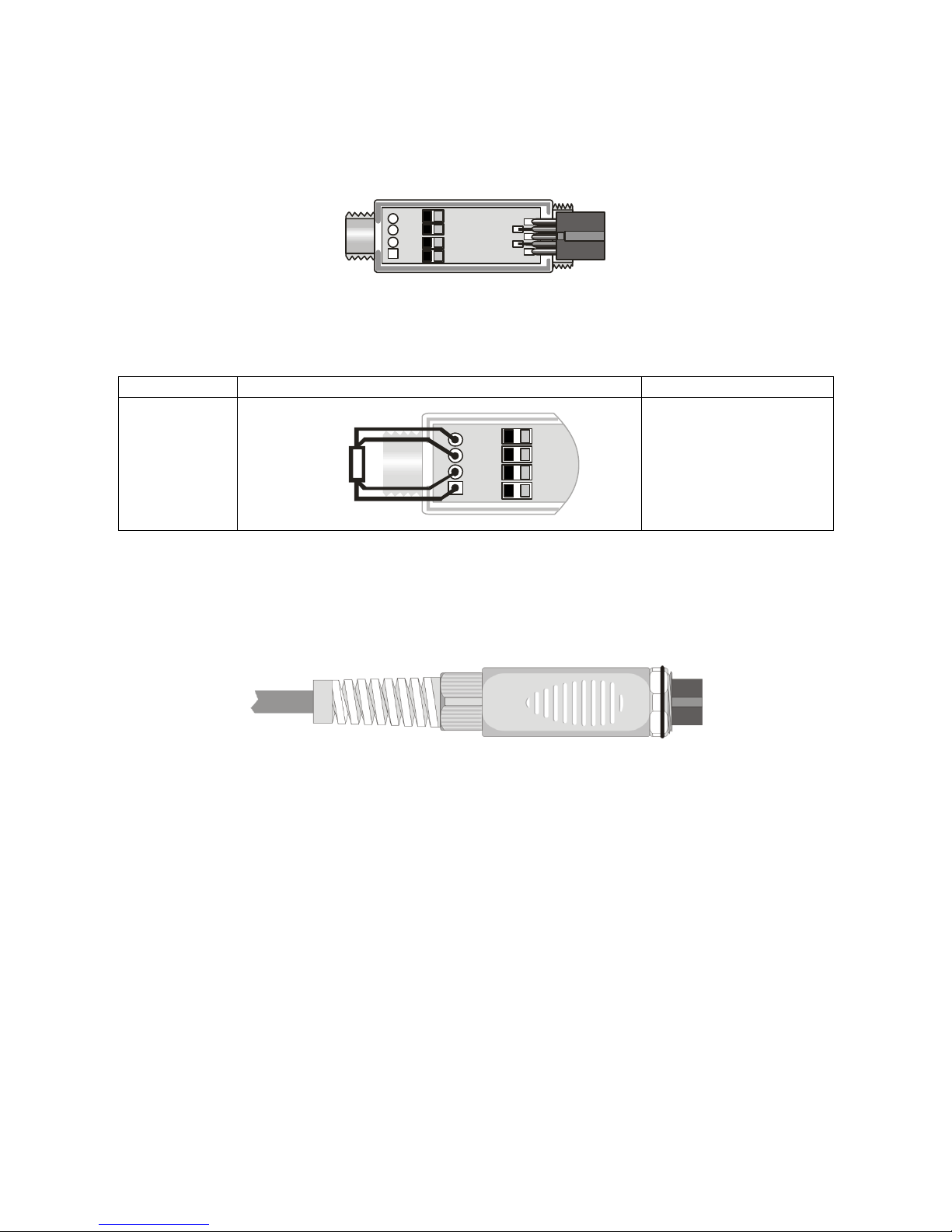
4.2.3 Direct connection of 4 wire Pt100 sensors
4 wire Pt100 sensors can be soldered directly
to the pins of the flying female connector
without making use of the TP47 board. The 4
wires of the Pt100 sensors have to be soldered
as indicated in the figure on the left. In order
to use this type of probe it is necessary to set
up the menu item “Probe Type” as described
at page 9. The P100 probe is recognized upon
turning on the instrument: connect the probe
when the instrument is switched off and then
turn it on.
Sensor
Direct soldering to the connector
Pt100 4
wires
View of the soldering side
of the flying female connector

- -
14
5.WARNINGS
1. Do not expose the probes to gases or liquids that could corrode the material of the sensor or the
probe itself. Clean the probe carefully after each measurement. Some pressure probe model are
suitable for measurement of non corrosive gases or air and dry and not liquid only: check the
membrane compatibility with the plant fluid.
2. Do not bend the probe connectors or force them upward or downward. Do not bend or force the
contacts when inserting the probe connector into the instrument.
3. Do not bend, deform or drop the probes, as this could cause irreparable damage.
4. Always select the most suitable probe for your application.
5. Do not use the temperature probes in presence of corrosive gases or liquids. The sensor
container is made of AISI 316 stainless steel, while the contact probe container is made from
AISI 316 stainless steel plus silver. Avoid contact between the probe surface and any sticky
surface or product that could corrode or damage it.
6. Above 400°C and below –40°C, avoid violent blows or thermal shocks to Platinum temperature
probes as this could cause irreparable damage.
7. To obtain reliable measurements, temperature variations that are too rapid must be avoided.
8. Temperature probes for surface measurements (contact probes) must be held perpendicular
against the surface. Apply oil or heat-conductive paste between the surface and the probe in
order to improve contact and reduce reading time. Whatever you do, do not use water or solvent
for this purpose. A contact measurement is always very hard to perform. It has high levels of
uncertainty and depends on the ability of the operator.
9. Temperature measurements on non-metal surfaces usually require a great deal of time due to the
low heat conductivity of non-metal materials.
10. Probes are not insulated from their external casing; be very careful not to come into contact
with live parts (above 48V). This could be extremely dangerous for the instrument as well
as for the operator, who could be electrocuted.
11. Avoid taking measurements in presence of high frequency sources, microwave ovens or large
magnetic fields; results may not be very reliable.
12. Clean the probe carefully after use. Clean the probe pressure chamber carefully. Avoid deposits
or incrustations left by the fluid coming into contact with the membrane, as with time this could
cause measurement errors.
13. Avoid inserting nails or spikes into the pressure chamber as the membrane could be
unintentionally torn.
14. In order to fix the probes, use a suitable fixed wrench, and possibly sealing gaskets.
15. Great attention must be paid while installing the probes in containers and tubes under
pressure. Also pay attention to the probes’bottom scale. In addition to the
irreparable damage, it can even cause serious physical damage to both the operator
and things. Before the probe a stop valve should always be present. Ensure that the
plant is not subject to abnormal or unexpected depressed fluid fluctuations.
16. The instrument is water resistant and IP67, but should not be immersed in water. The probe
connectors must be fitted with sealing gaskets. Should the instrument fall into the water, check
for any water infiltration. Gently handle the instrument in such a way as to prevent any water
infiltration from the connectors’side.

- -
15
6.INSTRUMENT SIGNALS AND FAULTS
The following table lists all error indications and information displayed by the instrument and
supplied to the user in different operating situations:
Display indications
Explanation
PROB
COMM LOST
This appears if the SICRAM module connected to the channel has already been
detected by the instrument, but is disconnected. At the same time an intermittent beep
is issued.
OVER
Measurement overflow: this appears if the pressure sensor exceeds the limit of 120% of
the bottom scale nominal value. Over 125%, the display indicates ERR.
Measurement overflow: this appears if the external temperature probe is measuring a
value exceeding the set measuring range.
ERR
This appears in the menu if a module has already been detected by the instrument, but
is disconnected.
PROB
ERR
A probe with SICRAM module has been inserted when not admissible for that specific
instrument.
SYS
ERR
#
Instrument management program error. Contact the instrument’s supplier and
communicate the numeric code # reported by the display.
CAL
LOST
Program error: it appears after turning on for a few seconds. Contact the instrument’s
supplier.
BATT TOO LOW
CHNG NOW
Indication of insufficient battery charge appearing on turning on. The instrument issues
a long beep and turns off. Replace the batteries.
### BAR ABS
probe ###bar absolute
### BAR DIFF
probe ###bar differential
### BAR GAUG
probe ###bar relative
### BAR SG
probe ###bar relative compared to 1 bar
### mBAR ABS
probe ###mbar absolute
### mBAR DIFF
probe ###mbar differential
### mBAR GAUG
probe ###mbar relative
PRBE_SER #### ####
serial number #### #### of the probe connected to the input
ERR
error
FUNC CLRD
max, min and average values cleared
NEW_ PROB_DET
new probe detected at the input
OVER
maximum limit exceeded
PLS_EXIT >>> FUNC
RES_FOR_FACT ONLY
please exit using ESC >>> function reserved to factory calibration
PRES_REL_TO_ZERO
ENTR_TO_MENU
press REL to reset differential probe or ENTER to access menu
prob ERR
error –unexpected probe
SYS ERR #
program error number #

- -
16
7.INSTRUMENT STORAGE
Instrument storage conditions:
Temperature: -25…+65°C.
Humidity: less than 90%RH without condensation.
Do not store the instrument in places where:
humidity is high;
the instrument may be exposed to direct sunlight;
the instrument may be exposed to a source of high temperature;
the instrument may be exposed to strong vibrations;
the instrument may be exposed to steam, salt or any corrosive gas.
The instrument case is made of ABS plastic: do not use any incompatible solvent for cleaning.

- -
17
8. LOW BATTERY WARNING AND BATTERY REPLACEMENT
The battery symbol
on the display constantly shows the battery charge status. To the extent that batteries have
discharged, the symbol “empties”. When the charge decreases still further it starts blinking.
In this case, batteries should be replaced as soon as possible.
If you continue to use it, the instrument can no longer ensure correct measurement. The memory
data are maintained.
If the battery charge level is insufficient, the following message appears when you turn the
instrument on: BATT TOO LOW
CHNG NOW
The instrument issues a long beep and turns off. In this case, replace the batteries in order to
turn the instrument back on.
To replace the batteries, proceed as follows:
1. switch the instrument off;
2. unscrew the battery cover counter clockwise;
3. replace the batteries (3 1.5V alkaline batteries –type AA);
4. screw the cover on clockwise.
Malfunctioning upon turning on after battery replacement
After replacing the batteries, the instrument may not restart correctly; in this case, repeat the
operation.
After disconnecting the batteries, wait a few minutes in order to allow circuit condensers to
discharge completely; then reinsert the batteries.
8.1 WARNING ABOUT BATTERY USE
Batteries should be removed when the instrument is not used for an extended time.
Flat batteries must be replaced immediately.
Avoid batteries leaking.
Always use good quality leak proof alkaline batteries. Sometimes on the market, it is
possible to find new batteries with an insufficient charge capacity.

- -
18
9. NOTES ABOUT WORKING AND OPERATIVE SAFETY
Authorized use
The technical specifications as given in chapter TECHNICAL CHARACTERISTICS must be
observed. Only the operation and running of the measuring instrument according to the instructions
given in this operating manual is authorized. Any other use is considered unauthorized.
General safety instructions
This measuring system is constructed and tested in compliance with the EN 61010-1 safety
regulations for electronic measuring instruments. It left the factory in a safe and secure technical
condition.
The smooth functioning and operational safety of the measuring system can only be guaranteed if
the generally applicable safety measures and the specific safety instructions in this operating
manual are followed during operation.
The smooth functioning and operational safety of the instrument can only be guaranteed under the
environmental and electrical operating conditions that are in specified in chapter TECHNICAL
CHARACTERISTICS.
Do not use or store the product in places such as listed below:
Rapid changes in ambient temperature which may cause condensation.
Corrosive or inflammable gases.
Direct vibration or shock to the instrument.
Excessive induction noise, static electricity, magnetic fields or noise.
If the measuring system was transported from a cold environment to a warm environment, the
formation of condensate can impair the functioning of the measuring system. In this event, wait
until the temperature of the measuring system reaches room temperature before putting the
measuring system back into operation.
Obligations of the purchaser
The purchaser of this measuring system must ensure that the following laws and guidelines are
observed when using dangerous substances:
EEC directives for protective labour legislation
National protective labour legislation
Safety regulations

- -
19
10.TECHNICAL CHARACTERISTICS
10.1 TECHNICAL INFORMATION ON THE MANOMETER –THERMOMETER
Instrument
Dimensions (Length x Width x Height) 140 x 88 x 38 mm
Weight 160 g (complete with batteries)
Material ABS
Display 2x4½ digits plus symbols
Visible area: 52x42mm
Operating conditions
Operating temperature -5 50°C
Warehouse temperature -25 65°C
Working relative humidity 0 90%RH without condensation
Protection degree of the case IP67
Power
Batteries 3 1.5V type AA batteries
Autonomy 200 hours with 1800mAh alkaline
batteries
Power absorbed with instrument off < 20 A
Connections
Input for probes 8-pole male DIN45326 connector
Unit of Measurement Pa, hPa, kPa, mbar, bar, atm, mmHg,
mmH2O, kgf/cm2, PSI, inchHg,
°C, °F
Measurement of temperature by Instrument
Pt100 measurement range -200 +650 °C
Resolution 0.1 °C
Accuracy 0.1 °C
Drift after 1 year 0.1 °C/year
EMC standard regulations
Security EN61000-4-2, EN61010-1 level 3
Electrostatic discharge EN61000-4-2 level 3
Electric fast transients EN61000-4-4 level 3,
EN61000-4-5 level 3
Voltage variations EN61000-4-11
Electromagnetic interference susceptibility IEC1000-4-3
Electromagnetic interference emission EN55020 class B

- -
20
10.2 ON LINE INSTRUMENT PROBES AND MODULES TECHNICAL DATA
10.2.1 Pressure measurement by module PP471
All TP704 and TP705 series Delta Ohm probes can be connected to the PP471 module. See the
table below for the technical specifications of the individual probes.
Technical characteristics
Accuracy ±0.05% of full scale
Full scale
pressure
Maximum
over-
pressure
Burst
pressure
Resolution
ORDER CODES
Accuracy
From 20 to
25°C
Operating
temperature
Connection
Differential
pressure
Relative
pressure
(compared to
atmosphere)
Absolute
pressure
NON insulated
membrane
Insulated
membrane
Insulated
membrane
10.0 mbar
350 mbar
400 mbar
0.01 mbar
TP705-10MBD
0.50 % FSO
0…60°C
Tube 5mm
20.0 mbar
350 mbar
400 mbar
0.01 mbar
TP705-20MBD
0.50 % FSO
0…60°C
Tube 5mm
50.0 mbar
350 mbar
400 mbar
0.01 mbar
TP705-50MBD
0.50 % FSO
0…60°C
Tube 5mm
100 mbar
350 mbar
400 mbar
0.1 mbar
TP705-100MBD
0.25 % FSO
0…60°C
Tube 5mm
200 mbar
250 mbar
TP704-100MBGI
0.25 % FSO
-10…+80°C
¼ BSP
200 mbar
600 mbar
700 mbar
0.1 mbar
TP705-200MBD
0.25 % FSO
0…60°C
Tube 5mm
400 mbar
450 mbar
TP704-200MBGI
0.25 % FSO
-10…80°C
¼ BSP
400 mbar
800 mbar
900 mbar
0.1 mbar
TP704-400MBGI
0.25 % FSO
-10…80°C
¼ BSP
500 mbar
1500 mbar
1800 mbar
0.1 mbar
TP705-500MBD
0.25 % FSO
0…60°C
Tube 5mm
600 mbar
1200 mbar
1500 mbar
0.1 mbar
TP704-600MBGI
0.25 % FSO
-40…125°C
¼ BSP
1.00 bar
3 bar
3.3 bar
1 mbar
TP705-1BD
0.25 % FSO
0…60°C
Tube 5mm
2 bar
2.2 bar
TP705BARO
0.25 % FSO
0…60°C
Tube 5mm
2 bar
TP704-1BGI
0.25 % FSO
-40…125°C
¼ BSP
2 bar
TP704-1BAI
0.25 % FSO
-40…120°C
¼ BSP
2.00 bar
6 bar
7 bar
1 mbar
TP705-2BD
0.25 % FSO
0…60°C
Tube 5mm
4 bar
4.5 bar
TP704-2BGI
0.25 % FSO
-40…125°C
¼ BSP
4 bar
TP704-2BAI
0.25 % FSO
-25…85°C
¼ BSP
5.00 bar
10 bar
12 bar
1 mbar
TP704-5BGI
0.25 % FSO
-40…125°C
¼ BSP
TP704-5BAI
0.25 % FSO
-25…85°C
¼ BSP
10.0 bar
20 bar
25 bar
0.01 bar
TP704-10BGI
0.25 % FSO
-40…125°C
¼ BSP
TP704-10BAI
0.25 % FSO
-25…85°C
¼ BSP
20.0 bar
40 bar
45 bar
0.01 bar
TP704-20BGI
0.25 % FSO
-40…125°C
¼ BSP
TP704-20BAI
0.25 % FSO
-25…85°C
¼ BSP
50.0 bar
100 bar
120 bar
0.01 bar
TP704-50BGI
0.25 % FSO
-40…125°C
¼ BSP
TP704-50BAI
0.25 % FSO
-25…85°C
¼ BSP
100 bar
200 bar
240 bar
0.1 bar
TP704-100BGI
0.25 % FSO
-40…125°C
¼ BSP
TP704-100BAI
0.25 % FSO
-25…85°C
¼ BSP
200 bar
400 bar
450 bar
0.1 bar
TP704-200BGI
0.25 % FSO
-40…125°C
¼ BSP
TP704-200BAI
0.25 % FSO
-25…85°C
¼ BSP
500 bar
700 bar
1000 bar
0.1 bar
TP704-500BGI
0.25 % FSO
-40…125°C
¼ BSP
TP704-500BAI
0.25 % FSO
-25…85°C
¼ BSP
Table of contents
Other Delta OHM Thermometer manuals

Delta OHM
Delta OHM HD 9212 User manual

Delta OHM
Delta OHM HD2307.0 User manual

Delta OHM
Delta OHM HD2108.1 User manual

Delta OHM
Delta OHM HD3406.2 User manual

Delta OHM
Delta OHM HD2178.1 User manual

Delta OHM
Delta OHM HD2205.2 User manual

Delta OHM
Delta OHM HD2328 User manual

Delta OHM
Delta OHM HD2127.1 User manual

Delta OHM
Delta OHM HD2107.1 User manual


