Delta OHM HD2178.1 User manual
Operating manual
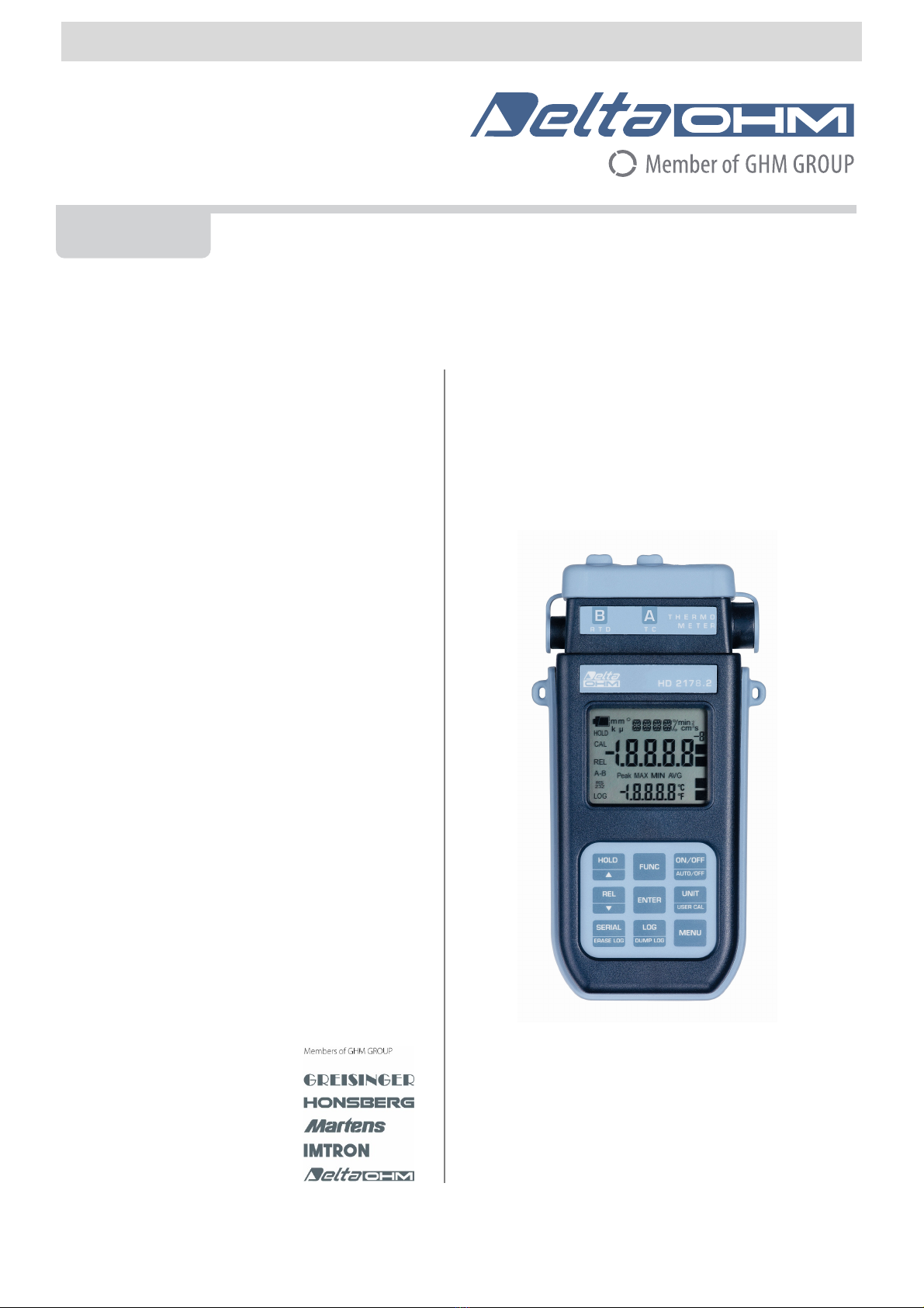
RTD / thermocouple thermometers
HD2178.1 – HD2178.2
www.deltaohm.com
Companies / Brands of GHM
English
Keep for future reference.

HD2178 - 2 - V2.3
CONTENTS
INTRODUCTION..................................................................................................................................................... 3
KEYBOARD AND MENU DESCRIPTION ............................................................................................................ 8
THE PROBES..........................................................................................................................................................14
TEMPERATURE MEASUREMENT ...............................................................................................................................14
Calibration of the RTD and thermocouple temperature probe in line with the instrument....................................14
Instructions to connect the TP47 connector for 4-wire Pt100, Pt1000 and Ni1000 probes ...................................15
Direct connection of 4 wire Pt100 sensors .........................................................................................................17
WARNINGS AND OPERATING INSTRUCTIONS ..............................................................................................18
INSTRUMENT SIGNALS AND FAULTS..............................................................................................................19
LOW BATTERY WARNING AND BATTERY REPLACEMENT.......................................................................21
INSTRUMENT STORAGE.....................................................................................................................................22
SERIAL INTERFACE AND USB ...........................................................................................................................23
STORING AND TRANSFERRING DATA TO A PERSONAL COMPUTER......................................................25
THE LOGGING FUNCTION -ONLY FOR HD2178.2......................................................................................................25
CLEARING THE MEMORY -ONLY FOR HD2178.2 ......................................................................................................25
THE PRINT FUNCTION ...........................................................................................................................................26
CONNECTION TO A PC........................................................................................................................................27
CONNECTION TO THE RS232C SERIAL PORT OF THE INSTRUMENT .............................................................................27
CONNECTION TO THE USB 2.0 PORT OF THE INSTRUMENT -ONLY FOR HD2178.2......................................................27
NOTES ABOUT WORKING AND OPERATIVE SAFETY..................................................................................28
INSTRUMENT TECHNICAL CHARACTERISTICS...........................................................................................29
TECHNICAL DATA OF PROBES AND MODULES IN LINE WITH THE INSTRUMENT ............................................................31
PROBES Pt100 4WIRES AND Pt1000 2WIRES............................................................................................................31
TEMPERATURE PROBES Pt100 SENSOR USING SICRAM MODULE.................................................................................32
ORDER CODES ......................................................................................................................................................33

HD2178 - 3 - V2.3
INTRODUCTION
The HD2178.1 and HD2178.2 are portable instruments with a large LCD display. They measure the
temperature using immersion, penetration or air contact probes. Input A accepts K, J, T, N or E
thermocouple type probes. Input B accepts probes with SICRAM module and Pt100 sensor probes
or probes which sensor can be a Pt100 4 wires, Pt1000 or Ni1000 2 wires.
The probes are fitted with automatic detection module, with the factory calibration settings already
being memorized inside.
The HD2178.2 instrument is a datalogger. It memorizes up to 80,000 samples which can be trans-
ferred from the instrument connected to a PC via the RS232C serial port or USB 2.0 port. The log-
ging interval, printing, and baud rate can be configured using the menu.
The HD2178.1 and HD2178.2 models are fitted with an RS232C serial port and can transfer the ac-
quired measurements in real time to a PC or to a portable printer.
The Max, Min and Avg function calculate the maximum, minimum or average values.
Other functions include: the relative measurement REL, the HOLD function, and the automatic
turning off that can also be disabled.
The instruments have IP66 protection degree.
This manual describes the HD2178.1 and HD2178.2 models: if not otherwise specified, the de-
scription is intended to be applicable to both models.

HD2178 - 4 - V2.3
RTD - Thermocouple Thermometer
HD2178.1

HD2178 - 5 - V2.3
HD2178.1
1. Input for thermocouple, standard miniature connector.
2. Input for probes, 8-pole DIN45326 connector.
3. Input for external power supply connector.
4. Battery symbol: displays the battery charge level.
5. Function indicators.
6. Secondary display line.
7. HOLD/key: freezes the measurement during normal operation; in the menu, increases the
current value.
8. FUNC key: displays the maximum (MAX), the minimum (MIN) and the average (AVG) of
current measurements. When pressed together with the UNIT/UserCal key, starts the calibra-
tion procedure for the probe connected to the instrument.
9. REL/key: enables the relative measurement (displays the difference between the current
value and the logged value when the key is pressed); in the menu, decreases the current value.
10. SERIAL key: starts and ends data transfer to the serial communication port.
11. MENU key: allows access to and exit from the menu.
12. ENTER key: in the menu, confirms the current selection.
13. UNIT/USER CAL key: during normal operation, selects the unit of measurement for the tem-
perature between °C or °F; when pressed together with the FUNC key, starts the calibration
procedure for the probe connected to the instrument.
14. ON-OFF/AUTO-OFF key: turns the instrument on and off; when pressed together with the
HOLD key, disables the automatic turn off.
15. MAX, MIN and AVG symbols.
16. Main display line.
17. Line for symbols and comments.
18. 8-pole MiniDin connector for RS232C. For the connection to PC (with cable HD2110CSNM or
C206) or printer (with cable HD2110CSNM).
HD2178 - 6 - V2.3
RTD – Thermocouple Thermometer
HD2178.2

HD2178 - 7 - V2.3
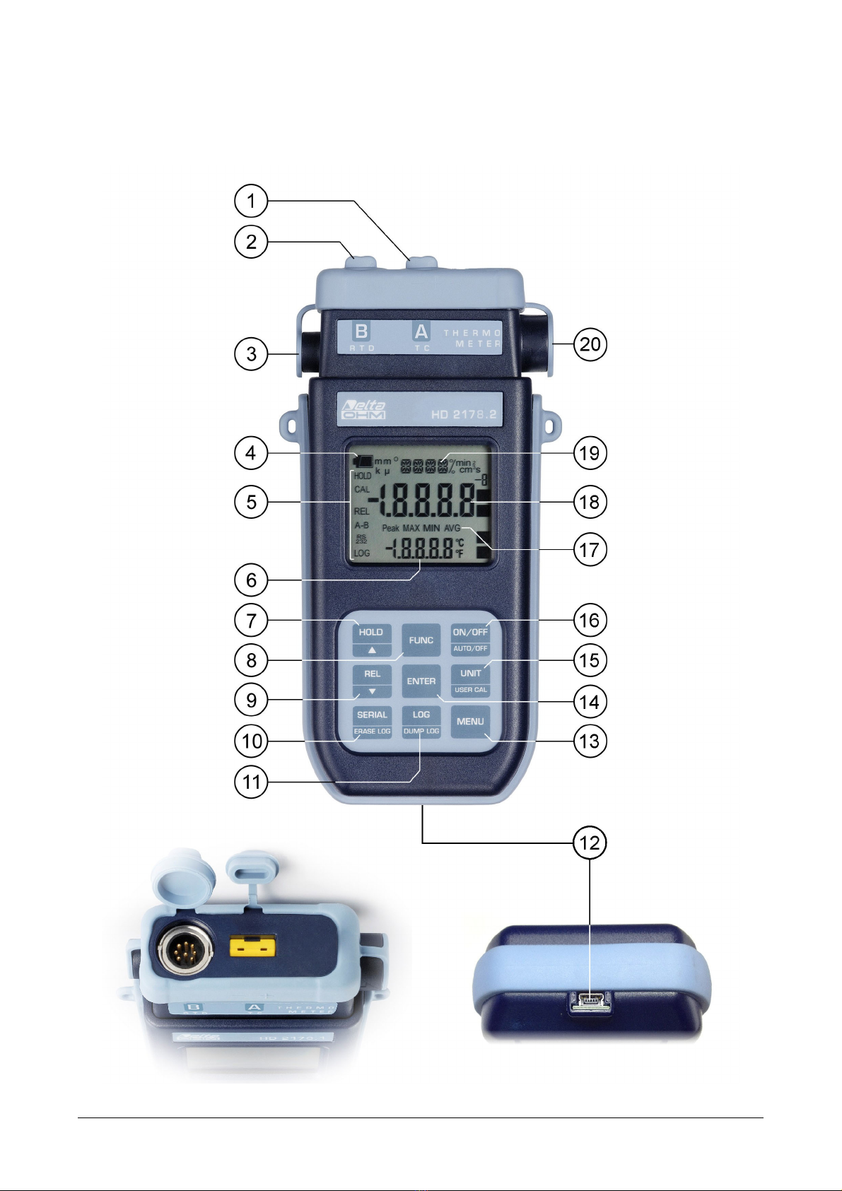
HD2178.2
1. Input for thermocouple, standard miniature connector.
2. Input for probes, 8-pole DIN45326 connector.
3. External auxiliary power supply connector input.
4. Battery symbol: displays the battery charge level.
5. Function indicators.
6. Secondary display line.
7. HOLD/key: freezes the measurement during normal operation; in the menu, increases the
current value.
8. FUNC key: displays the maximum (MAX), the minimum (MIN) and the average (AVG) of
current measurements. When pressed together with the UNIT/UserCal key, starts the calibra-
tion procedure for the probe connected to the instrument.
9. REL/key: enables the relative measurement (displays the difference between the current
value and the logged value when the key is pressed); in the menu, decreases the current value.
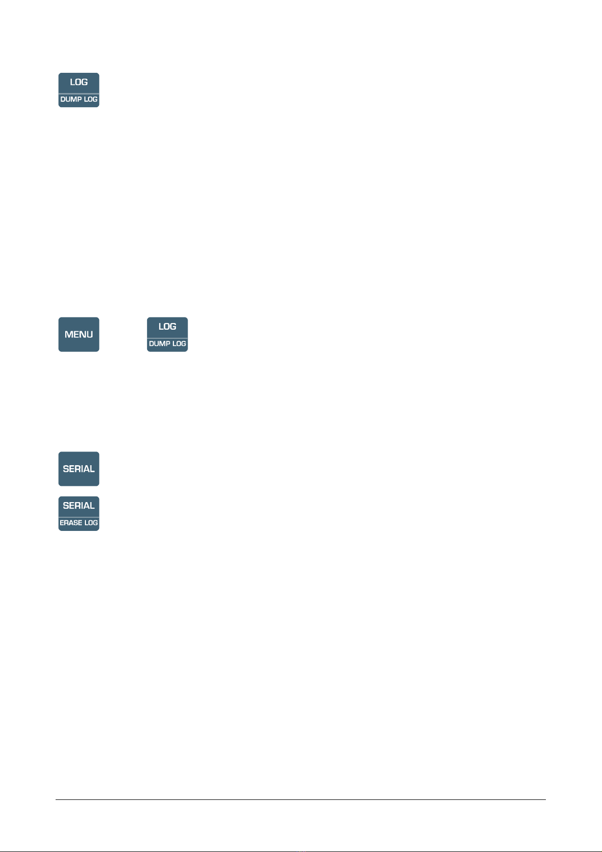
10. SERIAL/ERASE LOG key: starts and ends data transfer to the serial communication port. In
the menu, clears the data contained in the instrument's memory.
11. LOG/DUMP LOG key: during normal operation, starts and ends the saving of the data in the
internal memory; in the menu, starts the data transfer from the instrument's memory to the PC.
12. Mini-USB type B connector for USB 2.0. For the connection to PC (with cable CP23).
13. MENU key: allows access to and exit from the menu.
14. ENTER key: in the menu, confirms the current selection.
15. UNIT/USER CAL key: during normal operation, selects the unit of measurement for the tem-
perature between °C, °F or °K; when pressed together with the FUNC key, starts the calibration
procedure for the probe connected to the instrument.
16. ON-OFF/AUTO-OFF key: turns the instrument on and off; when pressed together with the
HOLD key, disables the automatic turn off.
17. MAX, MIN and AVG symbols.
18. Main display line.
19. Line for symbols and comments.
20. 8-pole MiniDin connector for RS232C. For the connection to PC (with cable HD2110CSNM or
C206) or printer (with cable HD2110CSNM).
HD2178 - 8 - V2.3
KEYBOARD AND MENU DESCRIPTION
Foreword
The instrument keyboard is composed of single-function keys, like the MENU key, and double-
function keys such as the ON-OFF/Auto-OFF key.
In the double-keys, the function in the upper part is the “main function”, while the one in the bottom
part is the “secondary function”. When the instrument is in standard measurement mode, the main
function is active. In the menu or in conjunction with the FUNC key, the secondary function is en-
abled.
The pressing of a key is accompanied by a short confirmation beep: a longer beep sounds if the
wrong key is pressed.
Each key specific function is described in detail below.
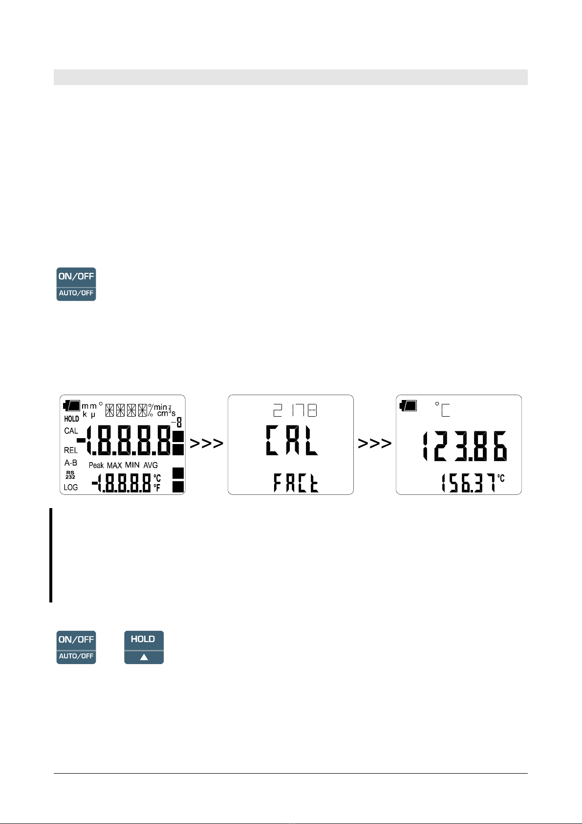
ON-OFF/Auto-OFF key
The instrument is turned on and off using the ON/OFF key. The turning on enables all display
segments for a few seconds, and then the type of calibration enabled (CAL FACT = factory cali-
bration; CAL USER = user calibration). Then an auto-test follows, including detection of the
probe connected to the input, and setting the instrument ready for normal measurement.
During turning on, should no probes with SICRAM module be connected to the input B,
the message "CH_B_ NO_SER_NUM" is scrolled in the line for symbols for a few seconds.
When the probe is inserted into the B input of a functioning instrument, the
"NEW_CH_B_PROB_DET" (New probe detected) message appears: as the probe's data
are captured upon turning the instrument on, it is necessary to turn the instrument off and
on again.
Replace the probes when the instrument is off.
+
Automatic turning off
The instrument has an AutoPowerOff function that automatically turns the instrument off after about
8 minutes if no key is pressed during the intervening time. The AutoPowerOff function can be dis-
abled by holding the HOLD key pressed down during the turning on phase: the battery symbol will
blink to remind the user that the instrument can only be turned off by pressing the <ON/OFF> key.
The automatic turning off function is disabled when external power is used. On the other
hand, it cannot be disabled when the batteries are discharged.

HD2178 - 9 - V2.3
FUNC key
It enables the display and logging of the maximum (MAX), minimum (MIN) and average (AVG)
value of the measurements captured by the probe connected to the instrument, updating them with
the acquisition of new samples. The acquisition frequency is once a second.
The MAX, MIN and AVG measurements remain in the memory until the instrument is on, even af-
ter exiting the calculation function. To reset the previous values and restart with a new measurement
session, press FUNC until the message “FUNC CLR” appears, then use the arrows to select YES
and confirm using ENTER.
Attention: the data captured using the Record function cannot be transferred to the PC.
HOLD/key
It increases the current parameter when used in the menu; when used in measurement mode, it
freezes the measurement in progress, and upon application of pressure on the key, the message
HOLD appears in the upper side of the display. To return to the current measurement, press the key
again.
Upon turning on the instrument, the AutoPowerOff function can be disabled by holding the HOLD
key down (please see the ON-OFF key description).
UNIT/UserCAL key
During measurement allows selection of the unit of measurement for the input temperature. By re-
peatedly pressing the function key, the different units of measurement are displayed in sequence:
1. °C Celsius degrees
2. °F Fahrenheit degrees
This setting changes the information displayed and the immediate print of data (SERIAL key). The
data recorded using the LOG function (HD2178.2) and sent to the printer or PC through the
serial port using the SERIAL function (HD2178.1 and HD2178.2), keep the chosen unit of
measurement and display it.
+
Calibration of the probe and selection of the type of calibration
Simultaneous pressure on the UNIT/UserCal and FUNC keys starts the calibration procedure of the
temperature probe connected to the instrument. Please see the paragraph dedicated to calibration on
page 14.
To select the type of calibration (USER=user or FACT= factory) press the UNIT/UserCal and
FUNC keys together, then use the arrows to select the desired item, and confirm using ENTER.
HD2178 - 10 - V2.3
ENTER key
In the menu, the ENTER key confirms the displayed parameter and then goes to the next one.
REL/key
In measurement mode, it displays the difference between the current value and that measured on
pressing the key. The REL message appears on the display; press the key again to return to the cur-
rent measurement.
When used in the menu, it decreases the current variable value.
MENU Key
The first menu item is accessed by initially pressing on the MENU key; press ENTER to go to the
following items. To modify the item displayed, use the arrow keys (and ). The current value is
confirmed by pressing the ENTER key and the display moves on to the next parameter; to erase the
set-up press the FUNC key.
To exit the menu, press the MENU key at any time.
The menu items are listed in this order:
1) Management of memorized data (only HD2178.2): the message
“>>>_LOG_DUMP_or_ERAS” (Transfer data or erase) is scrolled in the comment line. The
center figure reports the number of free memory pages (FREE). All memory data are erased
by pressing SERIAL/EraseLOG. By pressing LOG/DumpLOG, the data transfer of the logged
data on the serial port is started: the “BAUD-RATE” must have previously been set to the
maximum value (please see the menu items described below and the paragraph "STORING
AND TRANSFERRING DATA TO A PERSONAL COMPUTER" on page 25).
2) SEL Tc (select thermocouple type): the currently used thermocouple type appears in the
comment line in inverted commas, while the message “SEL tc" appears in the other two
lines. Use the arrow keys (and ) to modify the type of thermocouple. The message in
the comment line changes by pressing the arrow keys.
3) CH B: the message “CH_B" appears in the comment line. The main line in the center of the
display shows the type of probe connected to the instrument. The following probes can be
connected to the input:
•temperature probes Pt100 complete with SICRAM module
•direct 4-wire Pt100 probes through module TP47
•2-wire Pt1000 probes through module TP47
•2-wire Ni1000 probes through module TP47
Upon turning on the instrument automatically detects the probes fitted with SICRAM mod-
ule: the “CH_B” menu item is configured as “Pt100 Sicr” and cannot be modified by the
user.

HD2178 - 11 - V2.3
When turned on, the temperature probes direct 4-wire Pt100, the Pt1000 and the Ni1000
display the message "CH_B_NO_SER_NUM" (no probe serial number); in this case the
probe type must be entered manually. Select Probe type using the MENU key, CH_B
and then the type of probe used with the arrow keys; confirm using ENTER.
4) Print and log interval: sets the interval in seconds between two loggings or data transfers
to the serial port. The interval can be set at 0, 1s, 5s, 10s, 15s, 30s, 60s (1min), 120s (2min),
300s (5min), 600s (10min), 900s (15min), 1200s (20min), 1800s (30min) and 3600s (1hour).
If the value 0 is set, SERIAL works on command: the sending of data to the serial port
is performed each time the key is pressed. Recording (LOG) is performed with one sec-
ond intervals even if the interval is set to 0. With an interval from 1 to 3600s, continuous
data transfer is started when the SERIAL key is pressed. To end the logging (LOG) and con-
tinuous data transfer operations (SERIAL with an interval greater than 0), press the same
key again.
5) Sleep_Mode_LOG (Automatic turning off during logging) (only HD2178.2): this func-
tion controls the instrument's automatic turning off during logging, occurring between the
capture of a sample and the next one. When the interval is lower than 60 seconds, the in-
strument will always remain on. With intervals greater than or equal to 60 seconds, it is pos-
sible to turn off the instrument between loggings: it will turn on at the moment of sampling
and will turn off immediately afterwards, thus increasing the battery life. Using the arrows
select YES and confirm using ENTER in order to enable the automatic turning off, select
NO and confirm to disable it and keep the instrument on continuously.
Note: even if Sleep_Mode_LOG=YES is selected, the instrument does not turn off for less
than one minute intervals.
6) YEAR: to set the current year. Use the arrows to modify this parameter and confirm using
ENTER.
7) MNTH (month): to set the current month. Use the arrows to modify this parameter and con-
firm using ENTER.
8) DAY: to set the current day. Use the arrows to modify this parameter and confirm using
ENTER.
9) HOUR: to set the current hour. Use the arrows to modify this parameter and confirm using
ENTER.
10) MIN (minutes): to set the current minutes. In order to correctly synchronize the minute, it is
possible to reset the seconds by pressing the UNIT key. Use the arrows to set the current
minute plus one, and as soon as that minute is reached press UNIT: this synchronizes the
time to the second. Press ENTER to go onto the next item.
11) BAUD_RATE: indicates the frequency used for the serial communication with the PC.
Values from 1200 to 38400 baud. Use the arrows to modify this parameter and confirm us-
ing ENTER. The communication between instrument and PC (or serial port printer)
only works if the instrument and PC baud rates are the same. If the USB connection is
used this parameter value is automatically set (please see the details on page 25).
HD2178 - 12 - V2.3
LOG/DumpLOG key - only HD2178.2
In measurement mode, this function starts and stops the logging of a data block to be saved in the
instrument's internal memory. The data logging frequency is set in the "Print and log interval"
menu parameter. The data logged between a start and subsequent stop represent a block.
When the logging function is on, the LOG indication is displayed, the battery symbol blinks and a
beep is issued each time a logging occurs; the battery symbol does not appear when using an
external power supply.
To end the logging, press LOG.
The HD2178.2 can turn off during logging between one capture and the next: the function is con-
trolled by the Sleep_Mode_LOG parameter. When the logging interval is less than one minute, the
logging instrument remains on; with an interval of at least one minute, it turns off between one cap-
ture and the next if the parameter Sleep_Mode_LOG=YES.
>>>
Dump LOG - only HD2178.2
When the LOG key is pressed after the MENU key, the transfer of the logged data on the serial port
is started.
Please see the paragraph dedicated to data transfer on page 25.
SERIAL key - only HD2178.1
SERIAL/EraseLOG key - only HD2178.2
In measurement mode, this function starts and stops the data transfer to the RS232C serial output.
According to the settings entered in the Print and log interval menu item, a single sample can be
printed if Print and log interval=0 or a continuous indefinite printing of the measured data can be
set up if Print and log interval=1…3600.
The printing operation is accompanied by the display of the RS232 symbol and the blinking of the
battery symbol; when using an external power supply the battery symbol does not appear.
Press SERIAL to end the continuous printing.
Before starting the printing with SERIAL, set the baud rate. To do so, select the Baud Rate menu
item and select the maximum value equal to 38400 baud by using the arrows. Confirm by pressing
ENTER.
The DeltaLog9 software for PC will automatically set the baud rate value during connection. If you
are using a different program than DeltaLog9, be sure the baud rate is the same for both the
instrument and the PC: the communication will only work in this way.

HD2178 - 13 - V2.3
>>>
Erase memory - only HD2107.2
When pressed after the MENU key, the SERIAL/ERASE LOG key permanently erases all the data
contained in the instrument's memory.

HD2178 - 14 - V2.3
THE PROBES
Input A accepts K, J, T, N or E thermocouple temperature probes. The thermocouple type is set up
by menu.
The connector contacts of thermocouple probe are polarized, they have to be put into the miniature
connector placed in the instrument on the right way. Usually the probes are marked with the symbol
+ and -: these symbols have to correspond to the relevant symbols placed on the rubber protection
of the instrument.
Input B accepts temperature probes fitted with the SICRAM module (with a Platinum Pt100 sensor
with 100Ωresistance) or with direct 4-wire Pt100, 2-wire Pt1000 and Ni1000 sensors. The excita-
tion current was chosen in order to minimize the sensor self-heating effects. The SICRAM module
acts as an interface between the sensor on the probe and the instrument: there is a microprocessor
circuit with memory that enables the instrument to recognize the type of probe connected and to
read its functioning information. The probes with SICRAM module are automatically detected by
the instrument, while the direct probes must be set up in the CH_B menu item (please see the de-
scription on page 10).
The SICRAM probes connected to the B input are detected during turn on, and this cannot be
performed when the instrument is already on, therefore if a probe is connected and the in-
strument is on, it is necessary to turn it off and on.
TEMPERATURE MEASUREMENT
In all versions the temperature sensor is housed at the end of the probe.
The response time for the measurement of the temperature in air is greatly reduced if the air is mov-
ing. If the air is still, stir the probe. The response times are longer than those for liquid measure-
ments.
The temperature measurement by immersion is carried out by inserting the probe in the liquid for at
least 60mm; the sensor is housed in the end part of the probe.
In the temperature measurement by penetration the probe tip must be inserted to a depth of at least
60mm, the sensor is housed in the end part of the probe. When measuring the temperature on frozen
blocks it is convenient to use a mechanical tool to bore a cavity in which to insert the tip probe.
In order to perform a correct contact measurement, the measurement surface must be even and
smooth, and the probe must be perpendicular to the measurement plane. A contact measurement is
hard to perform due to various factors: the operator must be experienced in handling the probe and
consider all the factors influencing it.
So as to obtain the correct measurement, the insertion of a drop of oil or heat-conductive
paste is useful (do not use water or solvents). This method also improves the response time.
The °C or °F unit of measurement can be chosen for display, printing, and logging using the
UNIT/UserCal key.
Calibration of the RTD and thermocouple temperature probe in line with the instrument
To calibrate the probes correctly, a knowledge of and abiding by the physical phenomena on which
the measurement is based is fundamental: this is the reason why it is recommended to abide by what
is reported below carefully, and only to perform new calibrations if technically proficient and using
the suitable equipment.

HD2178 - 15 - V2.3
The probes fitted with SICRAM module are calibrated in the factory and the calibration pa-
rameters are recorded in the module. All RTD probes with direct input are checked for confor-
mity with class A tolerance according to norm IEC751 - BS1904 - DIN43760.
The instrument is provided with the FACT (factory) calibration. The user is also able to perform a
USER calibration of instrument+probe. The calibration information is saved in the instrument
memory and not in the probe. The same correction is applied to any probe connected to the input: it
is therefore implied that the USER calibration should only be used with a precise probe: the one
used during calibration and no other probe.
To pass from the user to the factory calibration and back, press the UNIT/UserCal and FUNC keys
together, then use the arrows to select the type of calibration, and confirm using ENTER.
Calibration sequence:
The calibration can be carried out on one or two points that should differ by at least 10°C and be
included in the probe functioning range.
Insert the probe into a thermostatic bath, the temperature of which is precisely known from a read-
ing taken on a sample reference thermometer. Wait for the measurement to stabilize.
Press simultaneously the UNIT/UserCal and FUNC keys, using the arrows select the USER calibra-
tion, and confirm with UNIT/UserCal.
Use the arrows to select the input to which the probe to calibrate is connected and choose input A
(to calibrate one thermocouple probe) or input B (to calibrate one RTD probe): confirm by pressing
ENTER key.
Use the arrows to select 1 (first calibration point) and confirm with ENTER. The "UP DOWN 1st
MEAS" (correct the first point using the arrows /) message is scrolled in the comment line. The
instrument display shows the measured temperature: use the arrows to correct the indicated value
until it coincides with the value measured by the sample reference thermometer.
Confirm by pressing ENTER.
To exit the procedure without performing the second point, select 0 and press ENTER.
To perform the second point, select the point 2 with the arrows and press ENTER.
The "UP DOWN 2nd MEAS" (correct the second point using the arrows /) message is scrolled
in the comment line.
Move the probe to the second thermostatic bath and wait for the measurement to stabilize. The in-
strument display shows the measured temperature: use the arrows to correct the indicated value un-
til it coincides with the value measured by the sample reference thermometer.
Confirm by pressing ENTER.
The procedure is now complete.
Instructions to connect the TP47 connector for 4-wire Pt100, Pt1000 and Ni1000 probes
All Delta Ohm probes are provided with a connector. The HD2178.1 and HD2178.2 instruments
also work with 4-wire direct Pt100, 2-wire Pt1000 and Ni1000 probes manufactured by other pro-
ducers: for the instrument connection is prescribed the TP47 connector to which the probe's wires
should be welded.
Note: the 3 wire Pt100 direct connection is not allowed.
HD2178 - 16 - V2.3
The instructions to connect the Platinum or Nickel probe to the module are provided below.
The module is supplied complete with fairlead and gasket for 5mm maximum diameter cables.
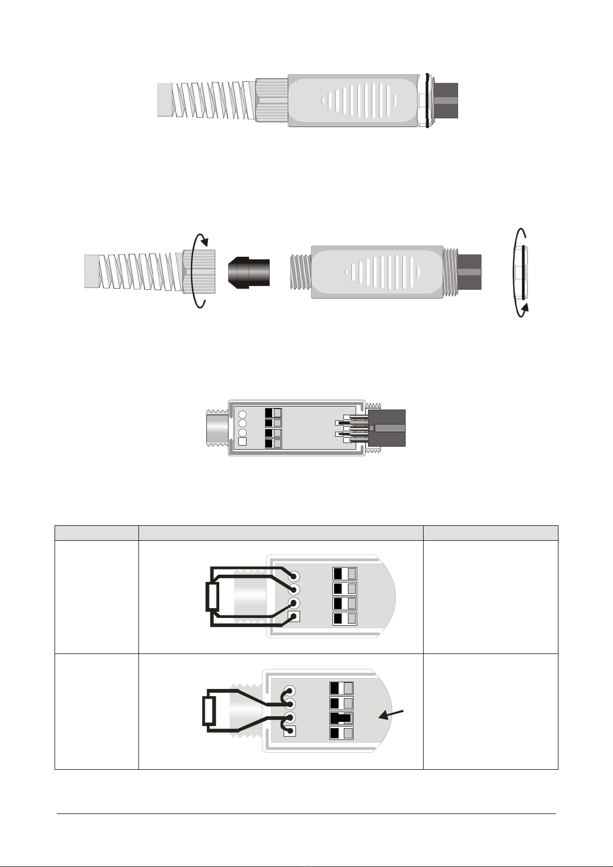
Do the following to open the module and connect a probe:
Unscrew the fairlead and extract the gasket, remove the label using a cutter, unscrew the ring on the
opposite side as illustrated in the figure:
Open the two module shells: the printed circuit to which the probe must be connected is housed in-
side. On the left there are the 1…4 points on which the sensor wires must be welded. The JP1…JP4
jumpers are in the center of the board. These must be closed with a tin bead for some type of sen-
sors:
1
2
3
4
Pt100 3 wires
Pt1000
Ni1000
Not Used
Before welding, pass the probe cable through the fairlead and gasket.
Weld the wires as shown in the table:
Sensor TP47 card connection Jumper to close
Pt100 4 wires
4JP4
3JP3
1JP1
2JP2
Pt100
4 wires
None
Pt1000 2 wires
JP4
4
JP3
3
JP1
1
JP22
Pt1000
2 wires
JP2
HD2178 - 17 - V2.3
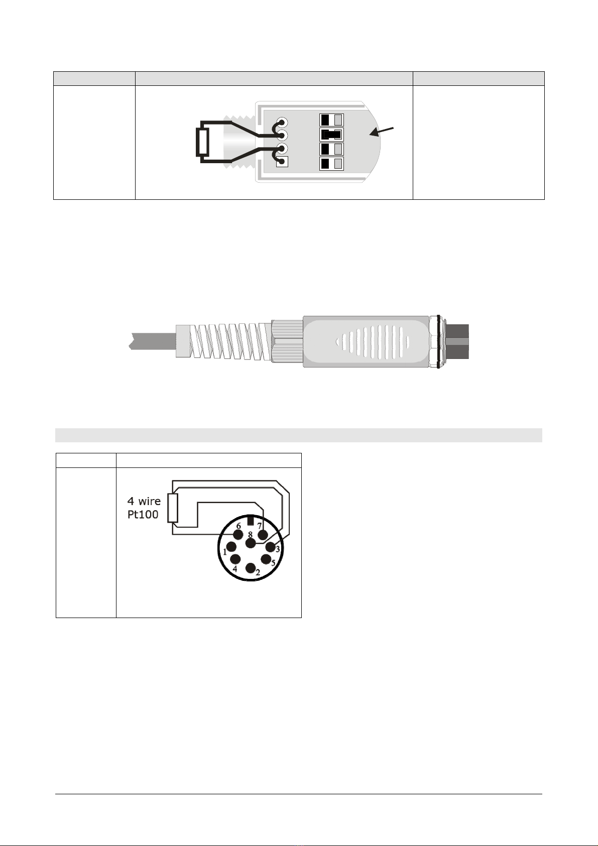
Sensor TP47 card connection Jumper to close
Ni1000
JP4
4
JP3
3
JP1
1
JP2
2
Ni1000
2 wires
JP3
Ensure the welds are clean and perfect. Once the welding operation is complete, close the two
shells, insert the gasket in the module, and screw the fairlead and the ring. At the other end of the
module, enter the ring with the O-Ring. Make sure the cable is not twisted while you are screwing
the fairlead. Now the probe is ready.
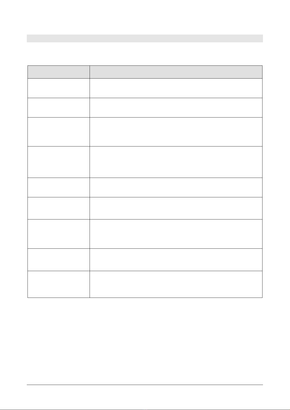
Direct connection of 4 wire Pt100 sensors
4 wire Pt100 sensors can be soldered directly
to the pins of the free female connector with-
out making use of the TP47 board. The 4
wires of the Pt100 sensors have to be soldered
as indicated in the figure on the left.
In order to use this type of probe it is neces-
sary to set up the menu item “Probe Type” as
described at page 10.
The P100 probe is recognized upon turning on
the instrument: connect the probe when the in-
strument is switched off and then turn it on.
Sensor Direct soldering to the connector
Pt100 4
wires
View of the soldering side
of the free female connector

HD2178 - 18 - V2.3
WARNINGS AND OPERATING INSTRUCTIONS
1. Do not expose the probes to gases or liquids that could corrode the material of the sensor or the
probe itself. Clean the probe carefully after each measurement.
2. Do not bend the probe connectors or force them upward or downward.
3. Do not bend or force the contacts when inserting the probe connector into the instrument.
4. Do not bend, deform or drop the probes, as this could cause irreparable damage.
5. Always select the most suitable probe for your application.
6. Do not use probes in presence of corrosive gases or liquids. The sensor container is made of
AISI 316 stainless steel, while the contact probe container is made from AISI 316 stainless steel
plus silver. Avoid contact between the probe surface and any sticky surface or substance that
could corrode or damage it.
7. Above 400°C and below –40°C, avoid violent blows or thermal shocks to Platinum temperature
probes as this could cause irreparable damage.
8. To obtain reliable temperature measurements, temperature variations that are too rapid must be
avoided.
9. Temperature probes for surface measurements (contact probes) must be held perpendicular
against the surface. Apply oil or heat-conductive paste between the surface and the probe in or-
der to improve contact and reduce reading time. Whatever you do, do not use water or solvent
for this purpose. A contact measurement is always very hard to perform. It has high levels of
uncertainty and depends on the ability of the operator.
10. Temperature measurements on non-metal surfaces usually require a great deal of time due to the
low heat conductivity of non-metal materials.
11. The sensor is not insulated from its external casing; be very careful not to come into contact
with live parts (above 48V). This could be extremely dangerous for the instrument as
well as for the operator, who could be electrocuted.
12. Avoid taking measurements in presence of high frequency sources, microwave ovens or large
magnetic fields; results may not be very reliable.
13. Clean the probe carefully after use.
14. The instrument is water resistant and IP66, but should not be immersed in water. Protect the
connectors from water by closing them well using their caps. The probe connectors must be fit-
ted with sealing gaskets. Should the instrument fall into the water, check for any water infiltra-
tion. Gently handle the instrument in such a way as to prevent any water infiltration from the
connectors' side.
HD2178 - 19 - V2.3
INSTRUMENT SIGNALS AND FAULTS
The following table lists all error indications and information displayed by the instrument and sup-
plied to the user in different operating situations:
Display indications Explanation
ERR This appears if the probe has already been detected by the instrument,
but is disconnected. At the same time an intermittent beep is issued.
CH_B COMM LOST This appears if the probe has already been detected by the instrument,
but is disconnected. At the same time an intermittent beep is issued.
OVER
or
UNDR
Measurement overflow: indicates that the probe is measuring a value
exceeding the measuring range.
LOG
MEM
FULL
Memory full; the instrument cannot store further data, the memory
space is exhausted.
NEW CH_B PROBE
DET
This message appears when a probe is inserted into a functioning in-
strument. Turn the instrument off and then back on again.
PROB
ERR
A probe with SICRAM module has been inserted when not admissible
for that specific instrument.
SYS
ERR
#
Instrument management program error. Contact the instrument's sup-
plier and communicate the numeric code # reported by the display.
CAL
LOST
Program error: it appears after turning on for a few seconds. Contact
the instrument's supplier.
BATT TOO LOW
CHNG NOW
Indication of insufficient battery charge appearing on turning on. The
instrument issues a long beep and turns off. Replace the batteries.

HD2178 - 20 - V2.3
The following table reports the indications provided by the instrument as they appear on the display,
together with their description.
Display indications Explanation
>>> CAL
_
MODE >>> KEY
_
UNIT
FOR_NEW_USER CAL_ calibration mode >>> press UNIT to start a new user calibration
>>>
_
LOG
_
DUMP
_
or
_
ERAS transfer or erase data
>>>
_
PRBE
_
TYPE type of probe connecte
d
1ST
_
MEAS UP DOWN correct the first point using the arrows /
2ND
_
MEAS UP DOW
N
correct the second point using the arrows /
BATT TOO LOW - CHNG NO
W
battery discharged - replace it immediatel
y
BAUDRATE >>
>
baud rate valu
e
CAL FACT factory calibration
CAL USER user calibration
CH
_
B
d
escription of probe connected to input B
CH
_
B COMM LOST communication loss with SICRAM probe of input B
CH
_
B
_
NO
_
SER
_
NUM serial number of probe connected with input B is absent
CH
_
B
_
SER #### ###
#
serial number #### #### of probe connected to input B
COMM STO
P
p
rinting complete
COMM STRT
p
rinting starte
d
DAY
_
da
y
DUMP
_
END data transfer complete
DUMP
_
In
_
PROG >>
>
data transfer in progress
ERR error
FUNC CLR max, min and average values clearing
FUNC CLRD max, min and average values cleare
d
HOUR hour
LOG In PROG logging in progress
LOG MEM FULL memory full
LOG
_
CLRD memory data cleare
d
LOG
_
STO
P
logging complet
e
LOG
_
STRT logging starte
d
MIN >>> USE
_
UNIT
_
TO
_
ZERO SEC minutes >>> use the UNIT key to reset the seconds
MNTH month
NEW
_
CH
_
B
_
PROB
_
DET new probe detected connected to input B
OVER maximum limit exceede
d
PLS
_
EXIT >>> FUNC RES
_
FOR
_
FACT
ONLY
p
lease exit using FUNC >>> function reserved to factory calibra-
tion
PRBE
_
SER #### ###
#
serial number #### #### of the connected probe
PRNT AND LOG INTV
p
rinting and logging intervals
PRNT INTV >>
>
p
rinting interval
PROB ERR
p
robe error
SEL CHA
N
selection of input for user calibration
SEL MEAS 1/2 select measurement 1 or 2
SLP
_
MODE
_
LOG turning off during recording mode
SYS ERR
#
p
rogram error number
#
UNDR minimum limit exceede
d
YEAR year
This manual suits for next models
1
Table of contents
Other Delta OHM Thermometer manuals

Delta OHM
Delta OHM HD2205.2 User manual

Delta OHM
Delta OHM HD3406.2 User manual

Delta OHM
Delta OHM HD2127.1 User manual

Delta OHM
Delta OHM HD2108.1 User manual

Delta OHM
Delta OHM HD2307.0 User manual

Delta OHM
Delta OHM HD 9212 User manual

Delta OHM
Delta OHM HD2107.1 User manual

Delta OHM
Delta OHM HD2304.0 User manual

Delta OHM
Delta OHM HD2328 User manual


