Delta Regis DRFF-520SS Parts list manual

1
DRFF-520SS Precision Screw FeederDRFF-520SS Precision Screw Feeder
DRFF-520SS
Setup & Operation Manual
Table of Contents:
Step Number Description Page
4... 23 Rail Adjustments 2-3
24 ... 31 Bit Guide Adjustments 3-4
32 ... 36 Brush Adjustments 4
38 ... 41 Chute Adjustments 4
42 ... 46 Final Adjustments 4-5
Delta Regis Tools, Inc. Phone: (772) 465-4302
7370 Commercial Circle Fax: (772) 465-4368
USA www.deltaregis.com
Delta Regis_DRFF-520SS_M_R0.0

DRFF-520SS Precision Screw Feeder
Check contents
Contents listed above
Turn top gate screw in clock-
wise direction until gate is
fully open
Turn side gate screw in clock-
wise direction until gate is
fully open
Slightly loosen the rail xing
screw in counter-clockwise
direction
Guide rail assembly out of
the feeder
Measure the diameter of the
screw to be used
3 mm screw used for demo
Slightly loosen screw shown
in counter-clockwise direc-
tion
Turn rail assembly over
Slightly loosen screws shown
in counter-clockwise direc-
tion
Remove screw found at rear
of rail assembly
Remove pre-installed spacer
shims
Choose the correct combina-
tion of spacer shims accord-
ing to screw diameter
Used 3.2 mm for demo
1 2 3 4
5 6 7 8
9 10 11 12
Setup instructions
Follow these step by step instructions to setup the DRFF-520SS according to the screw’s thread diam-
eter and screw’s head height.
DRFF-520SS Precision Screw Feeder
AC Power Adapter
Hex Wrench (2 mm)
Measurement Shim (1x 2.0 / 1.5 / 1.2 / 1.0 / 0.8 mm)
Spacer Shim (10x 0.5 mm/ 2x 0.2 mm) 3x 0.5mm / 1x 0.2 mm pre-installed
Large Stopper (Use with M2.0 mm - M5.0 mm) Small Stopper pre-installed
Grounding Cable
DRFF-520SS Precision Screw Feeder
Adjustment Tool
Delta Regis Tools, Inc. Phone: (772) 465-4302
7370 Commercial Circle Fax: (772) 465-4368
USA www.deltaregis.com
2

DRFF-520SS Precision Screw Feeder
Setup instructions (continued)
Insert the spacer shims into
rail assembly
Install and tighten screw
removed from step 10
Choose correct combination
measurement shims accord-
ing to screw diameter
+0.2 mm
Insert measurement shims
into rail assembly as shown
With the previous screws
loosened, squeeze the rail
sides until the rails bottom
against the measurement
shims
Tighten screws in steps 7 & 9 Remove measurement shims Place screw into rail groove...
...and test to ensure smooth
movement from front to back
of rail
Guide rail assembly into the
feeder
...and push until rail stops
Note - the bent angle of the
rail assembly slides under the
sensor plate
Tighten the rail xing screw
in clockwise direction
Measure the fastener head
height
Used 2.5 mm for demo
Slightly loosen screws shown
in counter-clockwise direc-
tion
Bit guide can now move
freely up and down
Choose the correct combina-
tion of measurement shims
according to the fastener
head height
+0.5 mm
12 13 14 15
19181716
23222120
27262524
Delta Regis Tools, Inc. Phone: (772) 465-4302
7370 Commercial Circle Fax: (772) 465-4368
USA www.deltaregis.com
3

DRFF-520SS Precision Screw Feeder
Setup instructions (continued)
Insert measurement shims
between rail and bit guide
Shimscannotrestontopofstopper;must
be pushed aside
Press down on bit guide Tighten screws from step 25 Remove measurement shims
Now the brush height can be
adjusted
Slightly loosen screws shown
in counter-clockwise direc-
tion
Grab 2 fasteners with twee-
zers
...and insert them into the
rail. Move brush up or down
until brush just touches the
screw heads
Tighten screws from step 33 Tilt the DRFF-520 slightly for-
ward. The previously inserted
screws should slide forward
and stop at the stopper
Now the chute can be ad-
justed
Slightly loosen the screws
shown in counter-clockwise
direction...
...and center chute with rail
assembly
Tighten screws from step 39 Slightly loosen screws shown Slightly loosen screws shown
31302928
35343332
39383736
43424140
DRFF-520SS Precision Screw Feeder
Delta Regis Tools, Inc. Phone: (772) 465-4302
7370 Commercial Circle Fax: (772) 465-4368
USA www.deltaregis.com
4

DRFF-520SS Precision Screw Feeder
Setup instructions (continued)
Take a screwdriver bit that
will be used to pick the
screws, center the x- and
y- axis
Bitguideshouldbe+0.2mmwiderthan
bit diameter
Tighten screws from step 42 Tighten screws from step 43 Turn the top gate screw
counter-clockwise until
lightly tightened and back o
two full turns clockwise
Nomorethan0.2mmgapbetweengate
and screw plate
Turn the side gate screw
counter-clockwise until
lightly tightened and back o
two full turns clockwise
Nomorethan0.2mmgapbetweengate
and rail
Plug AC power adapter into
the back of feeder...
...and plug AC power adapter
into proper outlet
Pour a few screws into the
hopper
Switch power ‘ON’
Thefeederstartstovibrateandroller
assemblybeginstoturn.Thefeederstops
automaticallywhenascrewarrivesat
the stopper
Test picking screws with a
magnetized bit to familiar-
ize yourself with the feeders‘
operation
If required, plug in the sup-
plied grounding cord...
...and connect the clip to any
metal grounding point
55545352
51504948
47464544
Delta Regis Tools, Inc. Phone: (772) 465-4302
7370 Commercial Circle Fax: (772) 465-4368
USA www.deltaregis.com
5
Operating instructions
After completing the setup adjustments, reconrm that the rail assembly is installed correctly (step 22) and
that the top and side gates are properly closed before lling the hopper (steps 47-48).

DRFF-520SS Precision Screw Feeder
Delta Regis Tools, Inc. Phone: (772) 465-4302
7370 Commercial Circle Fax: (772) 465-4368
USA www.deltaregis.com
6
With the power ‘OFF’and the accessory box removed. Ensure no foreign materials are loaded
into hopper. Pour in screws until they are approximately 1 - 2 mm below the bottom of the rail.
Replace cover (accessory box) on hopper opening. Keep cover on at all times while feeder is in
use.
The hopper can hold approximately 200 - 220 cc of screws. All objects other than applied screws
are deemed as foreign material which should be removed rst or they will aect the perfor-
mance of this feeder.
Overall Length of Fastener < 10 mm
Overall Length of Fastener < 19 mm
Plug in the AC power adapter supplied with the feeder into the feeder rst. Then plug the AC
power adapter into proper outlet. Connect ground cable. Turn the power switch ‘ON’ at the top
right side of the screw hopper. The power indicator will illuminate, the overload LED will illumi-
nate momentarily and the buzzer will emit a short ‘beep‘. The roller assembly will turn and the
rail assembly will vibrate. The feeder will start to feed screws to the bit guide.
Make sure the bit type in your electric screwdriver matches the head of the
screw and the bit is magnetized before use. (Bits that are not magnetized will
not work - For stainless steel applications, a vacuum pickup is required).
Hold the screwdriver, place the driver bit above the bit guide as shown. You do
not need to aim directly for the head of the screw, allow the point of the screw-
driver bit to move down the bit guide and engage into the recess of the screw
head.
· Do not push the driver down with too much force when picking up the screw or it will damage
the rail assembly
· Do not deliberately apply force on the rail assembly as this will damage the feeder
Caution
Picking screws
Powering ‘ON’
Loading the hopper
Operating instructions (continued)

DRFF-520SS Precision Screw Feeder
Operating instructions (continued)
Delta Regis Tools, Inc. Phone: (772) 465-4302
7370 Commercial Circle Fax: (772) 465-4368
USA www.deltaregis.com
7
A - Vibration Timer: Adjustable time delay, controls how long the rail continues to vibrate
after a screw is detected at the pick-up position.
B - Drum Timer: Adjustable time delay, controls how long the drum and brush continue to
operate after a screw is detected at the pick-up position.
C - Vibration Intensity: Allows for adjustment of the intensity of the vibration for proper screw
feeding.
Note - When making adjustments to the above controls, please use the included adjustment tool and
do not force the control past its stopping points. Little eort is required to make adjustments. Forcing
the controls past their stopping points will damage the feeder and void the warranty.
E - Gates: The top and side gates perform two functions - they allow the feeder to
accommodate dierent rail/screw adjustment settings and they
can be opened fully to allow the rail to be removed for setup purposes.
It is extremely important that the gates be properly closed (steps 47-48)
before the feeder is put into service.
Indication LED:
F2 - Overload Indicator: Lights briey when the feeder is powered on and provides a visual
indication if the feeder is overloaded.
G - Ground Connection: Used with included ground cable to bond the feeder to a grounding
point in the workstation.
H - DC Power Input: 15 VDC input connection for the AC power adapter provided with the
feeder.
I - Power Switch: Illuminated switch used to turn the feeder ‘ON/OFF’.
Location of controls and components

DRFF-520SS Precision Screw Feeder
Delta Regis Tools, Inc. Phone: (772) 465-4302
7370 Commercial Circle Fax: (772) 465-4368
USA www.deltaregis.com
8
PROBLEM PROBABLE CAUSES SOLUTION
Feeder does not power on or
constant buzzing sound when
power switch is ‘ON‘
Feeder is unplugged
Plug AC power adapter in the
feeder and switch power switch
to ‘ON‘ position
Faulty power switch, motor or
PCB
Return unit to authorized service
center for evaluation
Roller assembly not rotating
Faulty motor Return unit to authorizes service
center for evaluation
Foreign object stuck in gears /
gears stripped
Power ‘OFF‘ feeder, remove any
objects that may have fallen into
the roller assembly gears / send
feeder to authorized service
center for evaluation
Feeder is not feeding screws
Screws are not falling into rail
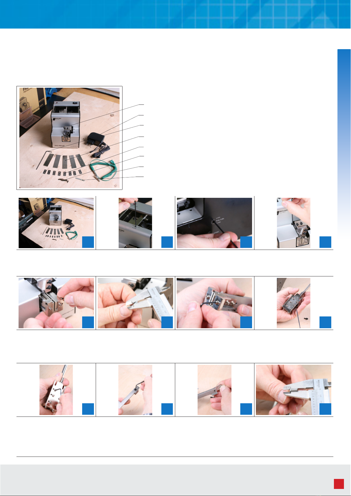
groove due to improper setup See steps 2 - 23
Dirty rail Power ‘OFF‘ the feeder, remove
and clean the rail assembly
Screw is caught at the holding
plate See steps 24 - 31
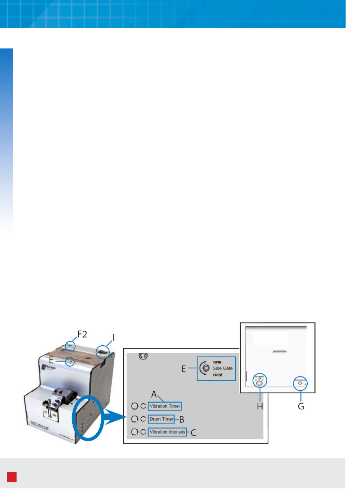
Vibration intensity not strong
enough for applied screw Increase the vibration intensity
Feeder not vibrating Return unit to authorized service
center for evaluation
Screws are not reaching the bit
guide for pick up
Feeder improperly set up for ap-
plied screw
Power ‘OFF‘ the feeder and fol-
low the Setup and Operation
Manual
Screwdriver bit unable to pick
up screw at bit guide
Bit guide not properly adjusted
to accommodate screwdriver bit
diameter
See steps 42 - 46
Screws are falling into the feeder Bit guide, rail assembly and/or
gates not properly adjusted
Power ‘OFF‘ the feeder, remove
any screws that have fallen into
the feeder and follow the Setup
and Operation Manual
Please read, understand, and follow all setup and operating instructions in this manual before using this
feeder. Do not attempt to modify this feeder. Repairs must only be performed by qualied repair person-
nel.
Warranty
Caution
Delta Regis DRFF-520SS are warranted for one year from the date of purchase against defects in mate-
rial and workmanship. This warranty does not cover damage due to transportation, abuse, misuse, or
improper service. Our sole remedy is to repair or replace (at our discretion) any unit found to be defec-
tive due to defects in material or workmanship. It is the responsibility of the user to return any product
thought to be defective, freight prepaid, to our warehouse for inspection and evaluation.
There is no warranty of merchantability or tness of purpose. In no event will Delta Regis Tools, Inc.
be liable for business interruptions, loss of prots, harm, injury, damage, personal injury, cost of delay,
or any other special, indirect, incidental, or consequential losses, costs, or damages.
Troubleshooting
Table of contents
Other Delta Regis Tools manuals