Delta-T WET150 User manual

Doc No.: WET150-UM-01-2
User Manual for the
WET150 sensor
Version 2.0

2⚫Notices Copyright © 2022 Delta-T Devices Ltd
Notices
UKCA conformity
The WET150 Sensor conforms to UK regulations regarding electromagnetic
emissions and susceptibility when used according to the instructions
contained within this user manual, and is UKCA marked by Delta-T Devices Ltd
CE conformity
The WET150 Sensor conforms to EC regulations regarding electromagnetic
emissions and susceptibility when used according to the instructions
contained within this user manual, and is CE marked by Delta-T Devices Ltd
FCC Emissions
CFR47 Pt 15 B [Unintentional Radiator emission limits as per
Pt 15.109]
Note: This equipment has been tested and found to comply with the limits for
a Class A digital device, pursuant to part 15 of the FCC Rules. These limits are
designed to provide reasonable protection against harmful interference when
the equipment is operated in a commercial environment. This equipment
generates, uses, and can radiate radio frequency energy and, if not installed
and used in accordance with the instruction manual, may cause harmful
interference to radio communications. Operation of this equipment in a
residential area is likely to cause harmful interference in which case the user
will be required to correct the interference at their own expense.
Design changes
Delta-T Devices Ltd reserves the right to change the design and
specification of its products at any time without prior notice.
Patents
The WET150 is protected under international law by the following:-
USA: Patent US7944220
Europe: Patent EP1836483
Australia: Patent AU2005315407
China: Patent CN101080631

3⚫Contents
Contents
Notices 2
Contents 3
Getting Started 5
Care and Safety 5
Introduction 6
Description 7
Parts and Accessories 8
Use with a WET150 Meter 9
Take a Reading 9
Options 9
WET150 Meter Buttons 9
Using the WET150 Meter to Change Address 10
Connecting to Loggers & Controllers 11
Wiring 11
Non-Delta-T loggers and systems wiring: 11
GP2 wiring (1): Using internal power 12
GP2 wiring (2): Using external power 13
Assigning Addresses using a GP2 14
Install DeltaLINK 14
1: Open DeltaLink Transparent Mode 15
2: Find out WET150’s current address 15
3: Change the address 16
Create GP2 Program 17
1: Add a WET150 SDI-12 Measurement 17
2: Sensor type Settings 19
3: Set Recording Intervals 21
4: Next Steps 21
Networking 22
Maximum cable length and network size 23
Power supply and communication 23
Warm-up time 24
Multiple WET150s in a network 24
Installation in the Ground 26
Surface installation and spot measurements 26
Installing at depth 27
SDI-12 commands 28

4⚫Contents Copyright © 2022 Delta-T Devices Ltd
Address Query 29
Address Assign 30
Identify 31
Take a measurement 32
Table of pre-configured measurements 33
Customising measurement sets 34
Specifications 36
Pore Water EC (ECp) accuracy 37
Edge Effects 27
Error Codes 37
Configuration 38
How it works 39
Sensing soils and substrates 39
Permittivity and soil composition 39
Converting permittivity to water content 40
Generic soil calibrations 42
Soil-specific calibrations 43
Technical Reference 44
Dielectric properties 44
Measuring Soil Moisture 45
Pore water conductivity 46
References 51
Definitions 52
Technical Support 57
Soil-specific Calibration 59
Laboratory calibration for non-clay soils 59
Laboratory calibration for clay soils 62
Soil-specific Parameter Derivation 65
Appendix 2 66
Soil-specific Parameters 66
Index 67

5⚫Getting Started
Getting Started
Thank you for purchasing the WET150, Delta-T’s robust and accurate sensor for
water content, electrical conductivity and temperature. To ensure you get the most
out of your sensor, we recommend the following steps:
1. Check you have all the equipment you need.
For a list of accessories and additional equipment see section “Parts and
Accessories”.
2. Check your sensor is properly configured for your intended use.
The WET150 is highly customisable to ensure maximum effectiveness in a
wide variety of applications. See section “Configuration”.
3. If using with the WET150 Meter:
See section “Use with a WET150 Meter”
4. If using in a permanent installation:
a. Check how to connect your sensor - See section “Connecting to Loggers
& Controllers”.
b. Check how to install your sensor See section “Installation in the Ground”.
5. Review the care and maintenance requirements of your sensor.
See section “Care and Maintenance”.
Care and Safety
•The pins of the WET150 are sharp.
Care must be taken and handling
precautions followed.
•Avoid touching the pins or exposing
them to other sources of static
charge, particularly when powered
up.
Keep the WET150 in its protective
package when not in use.
•Take care when attaching cables to ensure that the connectors are clean,
undamaged, and properly aligned before pushing the parts together.
•Do not pull the WET150 out of the soil by its cable.
•If you feel strong resistance when inserting the WET150 into soil, it is
likely you have encountered a stone. Stop pushing and re-insert at a new
location.
•WET150 is unsuitable for use in hard soils unless holes are pre-formed.
Rough handling may cause irreparable damage to the pins
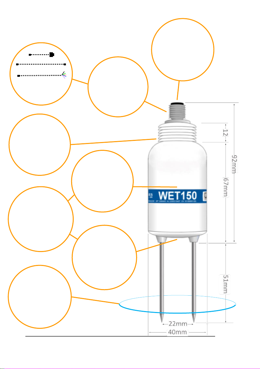
6⚫Introduction
Introduction
Cables
To Meter
Extension cables
To GP2 and other
loggers
Connector
Fully waterproof
M12 connector
Installation
Threads enable
extension rods to be
screwed on for easy
insertion in augured
holes –minimising soil
disturbance Detectors
Soil moisture content
and EC are detected by
sensitive circuits
operating at 100MHz
Sensing field
Extends ~100mm into
the soil, but field is
strongest close to the
rods - install carefully
to avoid air gaps
SDI-12
Industry-standard digital
interface, compliant to
version 1.3
Outputs
Sophisticated correction
algorithms ensure
accurate readings across
the full range of water
content, EC and
temperatures
Temperature
Thermistor is located
within the base –
equilibrates to the soil
temperature when
installed, less well for
portable
measurements

Introduction ⚫7
Description
The WET150 Sensor is a multi-parameter sensor for use in soils, substrates and
other growing media. It measures the dielectric properties of the soil and
calculates:
▪Water Content
▪Electrical Conductivity
▪Temperature
The sensor converts the measured dielectric properties into Water Content over
the full range, 0 to 100%, being most accurate over 5 to 100% water content and
over 0 to 500 mS/m soil bulk conductivity
1
. Generalised calibrations are provided
for most common soil types.
The WET150 Sensor also measures the bulk electrical conductivity of soil (ECb) over
0 to 2000 mS/m, being most accurate, ±(10 mS/m + 6%), from 0 to 1200 mS/m.
It also calculates Pore Water Conductivity, the electrical conductivity of the water
within the pores of the soil (ECp).
Temperature is measured by a miniature sensor built into the body of the sensor.
The WET150 Sensor works with the WET150 Meter and the GP2 logger controller.
It can also be used with other SDI-12 loggers, and with SDI-12 fertigation and
irrigation control systems.
Advantages of the WET150 Sensor
•Fast, accurate, adaptable and easy to use
•Rapid measurements (<0.5 seconds) of all 3 parameters
•In-situ Pore Water Conductivity measurements
•Easy insertion into growing media and soil
•Works with many different soils and growing media
•Stable, accurate readings from
•5 to 100% water content
•0 to 1200 mS.m-1
•-20 to +60°C
•Lightweight ergonomic design
•Versatile SDI-12 digital output
•Systems integrator friendly
•Wide choice and customisable settings, outputs and units
•Low power for long battery life
•2-year warranty extends to 5 years if registered on delivery
1
Best accuracy is achieved with a calibration matching the soil / substrate

8⚫Parts and Accessories
Parts and Accessories
WET150 sensor
WET150 Kit
WET150 + WET150 Meter
SMSC/lw-05
5m cable with 200 mm flying
leads.
Connects WET150 to GP2
directly, or via SDI-12 network
of EXT/5W-xx cables
EXT/5W-01
EXT/5W-05
EXT/5W-10
EXT/5W-25
1 m, 5 m,10 m and 25 m
extension cables with 5-way
M12 connectors. Connects
WET150 to an SDI-12 sensor
network
GP2-STP1
4-pin network T- Piece for
networking of SDI12 sensors
and EXT/5W-xx cables. Not to
be used for logger
communication networks.
GP2-NTP
5-pin network T- Piece with
continuous screen, for
connection of loggers and
EXT/5W-xx cables.
ML/EX50
ML/EX100
Extension tubes,
50 and 100 cm
SM-AUG-100
Spiral Auger 1.2 m

Use with a WET150 Meter ⚫9
Use with a WET150 Meter
The WET150 Meter Kit enables portable monitoring of water
content, electrical conductivity and temperature. It can also
be used to change the address of an SDI12 sensor.
Settings for soil type, conductivity units and temperature
units can be customised.
For more details see the WET150 Kit Quick Start Guide.
Take a Reading
1. Gently insert WET150 pins into soil or substrate.
2. Press READ to take and display water content,
temperature and pore water conductivity.
Options
Water content can be displayed as volumetric water content
(%) using the Mineral, Organic, Peat mix, Coir, Mineral wool
or Custom
2
calibrations; or the meter can display the RAW (unconverted)
permittivity reading (ε’) which has no units.
Temperature can be displayed in °C or °F.
EC is displayed as the pore water conductivity, ECp, in mS.m-1, for the chosen soil
type; or the soil bulk conductivity, ECb, when the RAW display option is selected.
Address can be a to z, A to Z or 0 to 9 ( 0 is not advised on a network)
WET150 Meter Buttons
READ –takes and displays a reading.
SET shows the settings menu. You can scroll up or down through these
options: Soil type, Units and Address and Contrast... Press SET to select
the highlighted menu and show the current setting in that menu.
Again, scroll up or down and press SET to confirm the choice and
return to the start-up screen. Alternatively, press READ to save the
setting, exit the menu and take a reading.
and scroll through the current options.
Auto-off - after 1 minute saves the current selection and switches off.
2
Please note customisation in the Meter does not change settings stored in the
sensor; see section “Configuration”, page 39

10 ⚫Use with a WET150 Meter
Using the WET150 Meter to Change
Address
The WET150 Meter can only take and display readings from WET150 sensors.
However, it can display and modify the address of most SDI-12 sensors with a
compatible power requirement.
3
In order to connect to a WET150 Meter, the
sensor would need to be fitted with an M12 connector –see section “Non-Delta-T
loggers and systems wiring” on page 11.
You can use this key stroke sequence on a WET150 Meter to change the SDI-12
address of any attached SDI-12 sensor, including WET150 or PR2s. Only attach one
sensor at a time to a WET150 Meter.
1. Press [SET] to wakes the Meter and displays the settings menu
2. Press [] twice to scroll down to the Address setting menu
3. Press [SET] to select that menu, and display the current SDI-12 address
4. Press [] or [] to scroll to the desired target address
5. Press [SET].
The Meter attempts to set that address:
▪Success is indicated by the brief appearance of the ✓symbol,
after which it reverts to the Settings menu.
▪Failure is indicated by , after 3 seconds it reverts to the Address setting
menu.
See also WET150 Kit Quick Start Guide
3
The Meter can supply approx. 100mA at 6 volts to an attached sensor
Each sensor must have a different address on an SDI-12
network or the network will not function properly. The
address must be set BEFORE attaching to the network.
Connecting to Loggers & Controllers ⚫11
Connecting to Loggers & Controllers
The WET150 is fully compliant with the SDI-12 communication protocol standard
(version 1.3). Because of this the WET150 can be used with any third-party logging
or metering device which is also SDI-12 compliant as well as with Delta-T Devices
GP2 logger controllers.
Wiring
GP2 Logger Wiring: See pages 12 and 13
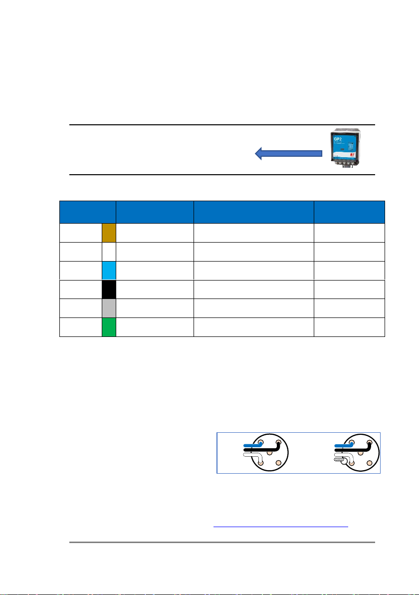
Non-Delta-T loggers and systems wiring
** Optional. The green wire is connected to the cable screen. The SDI-12
specification does not require the green wire / cable screen connected. If there is a
lot of electrical noise in the environment, connecting the green screen wire to
ground in the logger or controller may help reduce the risk of data corruption. Note
that for a continuous screen connection it is necessary to use the NTP T-piece.
For other connection details to third-party loggers and controllers please consult
the SDI-12 sections of those products’ manuals.
For SDI-12 screw terminal cable
connector information see the SDI-12
for GP2 User Manual. See also
“Power supply and communication”
on page 23
If ECp and water content values are being returned from the WET150 sensor,
remember to review the soil parameters and adjust them if required –see section
“SDI-12 commands” (page 28), and the WET150 SDI-12 Programmer’s Guide.
Wire colour
Logger or
controller
SDI-12 function
M12 connector
pin
Brown
Not connected
1
White
+12V 0.5A
Network power
2
Blue
GND
Ground (for power and data)
3
Black
DATA
Data (send and receive)
4
Grey
Not connected
5
Green
Not connected **
(Cable screen) **
Shell / nut
4
4
51
3
2
GROUND
SDI-12 DATA
SDI-12 POWER
SCREEN (if present)
4
4
51
3
2
GROUND
SDI-12 DATA
SDI-12 POWER

12 ⚫Connecting to Loggers & Controllers
GP2 wiring (1): Using internal power
The GP2 logger controller incorporates a program-controlled power rail specifically
for SDI-12 applications. This 12V supply is generated from the internal logger
battery pack via a voltage step-up circuit and is current limited in case of faults on
the SDI-12 network.
SDI-12 sensors typically require a 3-wire connection: Power, Ground and Data. This
is the case with the WET150 but the cabling system includes additional wires which
are not normally used within an SDI-12 network.
To create an SDI-12 network based upon a GP2 logger controller, use cable type
“SMSC/lw-05” to bring the network connections out of the GP2 case. This is a
shielded 5-way, 5-metre-long cable with bare wires on one end and a 5-way M12
connector on the other. Use this to connect one WET150 directly to a GP2, or with
the addition of other 5-way M12 extension cables and T-pieces, connect multiple
sensors in a network.
** Optional. The green wire is connected to the cable screen. The SDI-12
specification does not require the green wire / cable screen to be connected.
If there is a lot of electrical noise in the environment,
connecting the green screen wire to the GND terminal
(with the blue ground wire) in the GP2 may help
reduce any risk of data corruption. The figure on the
right illustrates the wire and terminal connections with
the optional green screen wire.
The brown and grey wires in cable type “SMSC/lw-05” are not normally required for
SDI-12 so should be insulated from shorting to any terminals inside the GP2, or they
may be trimmed off. The same applies to the green screen wire if it is not used.
4
0.5A assumes good quality alkaline AA cells are used in the GP2. Other battery
types may deliver lower maximum current drain.
Wire colour
GP2 terminal
(SDI-12 block)
SDI-12 function
M12 connector
pin
Brown
Not connected
1
White
+12V 0.5A4
Network power
2
Blue
GND
Ground
(for power and data)
3
Black
DATA
Data (send and receive)
4
Grey
Not connected
5
Green
Not connected**
(Cable screen) **
Shell / nut

Connecting to Loggers & Controllers ⚫13
Power is automatically supplied when the WET150 sensor is selected in the
DeltaLINK program.
GP2 wiring (2): Using external power
The WET150 is a highly energy efficient sensor. Depending upon the measurement
frequency and the number of WET150 sensors in the network, the internal GP2
logger/controller batteries are capable of providing power for many tens of
thousands of sensor readings over periods longer than a year.
If the WET150 is used in conjunction with other more power-hungry SDI-12
sensors, it may be desirable to use a larger external power supply for the SDI-12
network. The functioning of the GP2 logger/controller itself can remain running on
its own internal batteries independently of an external power source for the SDI-12
network.
To use an external power supply for the SDI-12 network, do not connect anything
to the GP2’s “+12 0.5A” power terminal. Instead wire the SDI-12 network power
(white wire on cable type “SMSC/lw-05”) to the external power source +12Vdc
terminal.
Wiring connection
diagram showing
external SDI-12 power
connections for the SDI-
12 network, along with
the optional green
screen wire.
Ensure there is a fuse or other protection in-line with this external power source in
case short-circuit faults develop on the SDI-12 network.
The Ground or 0V terminal of the external power source should be wired into the
GND terminal on the GP2, along with the Ground wire of the SDI-12 network (blue
wire on cable type “SMSC/lw-05”).
In the external power supply configuration shown above, power is permanently
applied to the SDI-12 network. This may not be the most desirable or efficient way
to run the network. An alternative would be to wire one of the GP2 internal relays
in series with the external power supply and the SDI-12 network power wire.
The GP2 logger/controller program can then be configured to switch in the power
only when taking measurements for greater external power efficiency.
e.g In DeltaLINK program’s Measurement, Power channel select RLY1.

14 ⚫Assigning Addresses using a GP2
Assigning Addresses using a GP2
If two sensors have the same address, then neither sensor will be able to
communicate and the SDI-12 network may not function. Each WET150 MUST have
a unique address before connecting it into a network of SDI-12 sensors.
The address of a new sensor is usually 0 (number zero). It can be changed to any
single digit address in the range 0 to 9, a to z or A to Z.
Use either a WET150 Meter connected directly to a WET150 sensor - see page 5, or
use a GP2 and PC running DeltaLINK as described below.
Install DeltaLINK
To operate the functions of the GP2 logger/controller, its companion computer
software “DeltaLINK” needs to be downloaded and installed. This PC software is
available from the Delta-T website at:
www.delta-t.co.uk/software/deltalink
DeltaLINK version 3.9 or later is required for use with the WET150. If your existing
install of DeltaLINK is older than this version, please install the latest version to gain
access to WET150 libraries.
DeltaLINK is available for Microsoft Windows only.
Once DeltaLINK is installed, connect the GP2 to your PC computer using the USB to
GP2 cable supplied with the GP2.
See also:
•GP2 User Manual
•SDI-12 for GP2 User Manual
•WET150 SDI-12 Programmer’s Guide
Assigning Addresses using a GP2 ⚫15
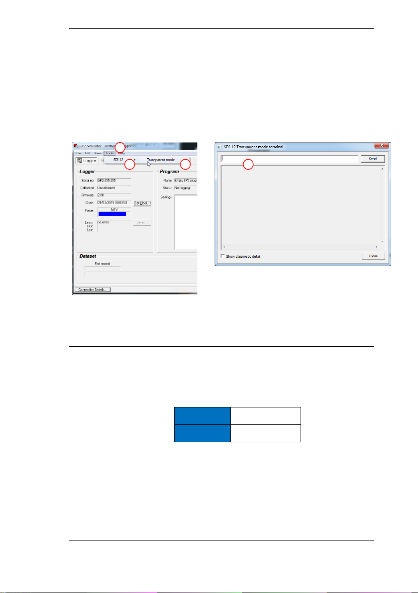
1: Open DeltaLink Transparent Mode
You need a GP2 connected to a PC running DeltaLINK v 3.9 or later.
With no other sensors on the network connect the sensor to the GP2 SDI-12
terminal.
In DeltaLINK select Tools, SDI-12, Transparent mode to open theSDI-12 Transparent
Mode Terminal as shown below.
Once the SDI-12 Transparent Mode Terminal is open, the GP2 behaves like a
transparent serial link between SDI-12 sensors and the PC.
2: Find out WET150’s current address
Send a command to tell the sensor to reply with its address.
You type
?!
Reply
a
We usually expect the address of a new sensor is to be zero, but it might not be. If
you already have another sensor with the same address on the same network the
command will not work.
?!
1
2 3 4
Any logger on COM1
Example:

16 ⚫Assigning Addresses using a GP2
3: Change the address
Send a command to change its address
You type
aAb!
Reply
b
The WET150 is now at address b. It could be anything from ato z, Ato Z, or 0to 9.
Avoid address 0 as it tends to be the default used in new sensors. Any sensors
which share the same address on the network will be unable to communicate.
Make a note of the address and the serial number. Clearly labelling the sensor (or
attached cable) will make setting up and troubleshooting much easier later on.
Later when you have finished giving each sensor a unique address, close the
Transparency Mode window and change the default GP2 program to create a
WET150 sensor type measurement with the correct address, and repeat this for
each sensor to go on the network. See also Create GP2 Program on page 17.
Tip for advanced users:
You can change the default Measurement Name to add useful metadata - for
example, by adding the address as a suffix so that Theta becomes Theta Z. But the
ECp calculation also uses the Permittivity and SoilTemp readings. So, in the
Calculation section of the ECp Measurement parameters change the Permittivity
name e.g. from Theta to Theta Z and likewise for the Temperature name if you
have also changed that, e.g. from SoilTemp to SoilTemp Z.
If you change Measurement name you must also change the Recording Rate entry
to match.

Create GP2 Program ⚫17
Create GP2 Program
1: Add a WET150 SDI-12 Measurement
Illustration: showing steps in the creation of a WET150 soil moisture sensor
measurement type in a GP2 program.
1. With DeltaLINK 3.9 or later running on your PC and connected to a
GP2 select Program.
2. Select Change.
3. Under Measurements click on “click to add a new item”.
4. Select Soil Moisture.
1
2
3
4
5
Change
18 ⚫Create GP2 Program
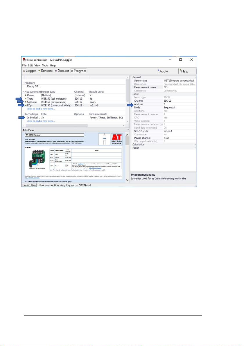
5. Select WET150 (complete). This will create three sensor
measurement types for soil moisture, electrical conductivity and
temperature, each with a default 1 hour recording period.
6. Select the Address to that of the WET150 sensor, as described on
page14. You should now see the following:
Illustration showing three sensor measurement types added to take readings from
a single WET150, for soil moisture, pore water conductivity and temperature. These
all have the same SDI-12 address, which in this example has been changed to 7
from the default 0 address. The default measurement period of 1 hour for all
readings can be also seen.

Create GP2 Program ⚫19
2: Sensor type Settings
This explains the Measurement and Parameter settings supplied in the WET150
sensor types in the DeltaLINK sensor library.
1. Sensor type: This is the name of the default WET150 Sensor type as
loaded from in the GP2 sensor library.
2. Change the Measurement name to anything useful e.g Theta (100mm)
or Treatment A.
If you have more than one WET150, give each measurement a unique
name here –e.g. “ECp at 100mm”. This information will be displayed
at the top of the column of measurements in the results table.
If you change a Measurement name then ensure it is updated in the
Recording Rate. (The program will object and fail to “Apply” if you don’t
do this).
Also if changing the WET150 Theta or SoilTemp Measurement names
you will need to use the same names used in the ECp Calculation
section.
Example: change the Measurement name to add useful metadata e.g.
Theta becomes Theta Z to display the address in the results. The ECp
calculation needs to use the Permittivity and SoilTemp readings. So, in
the Calculation section of the ECp Measurement parameters, change
the Permittivity name from Theta to Theta Z and likewise for the
Temperature name, if you have also changed that, e.g. from SoilTemp
to SoilTemp Z.
Showing the
addition of
address Z to
the WET150
Measurement
names

20 ⚫Create GP2 Program
3. Address: Enter the WET150 address so the GP2 will know
which sensor to contact. You must do this.
Use DeltaLINK, SDI-12, Transparent mode (or a WET150 Meter)
to give it a unique address before putting it on the SDI-12
network with other sensors, or else the network will crash.
See also Assigning Address on page 14.
4. Mode: The default WET150 sensor type uses the SDI-12
Sequential data measurement and reporting method.
See also Concurrent Measurements on page 24.
5. Additional: No action required. The default value cannot be
changed. The additional features are of use to less capable
loggers from other manufacturers, which can’t do maths as
well as the GP2).
6. Send data Command: No action required. Your GP2 logger
knows which D command to send, so this is not something you
need to worry about.
(Note for other logger users: The Dn command is sent by the
logger to retrieve the results when the sensor is ready (n can
be 0 to 8). In reply the sensor may send up to 76 characters to
the logger. The number of characters required for each
reading can vary: depending, for instance, on whether
readings are concurrent or sequential. So additional
commands, D1–D8, are available if necessary.
See also WET150 SDI-12 Programmers Guide)
7. SDI-12 units: options:
Soil moisture: % or m3.m-3.
Pore water conductivity: mS.m-1 mS.cm-1 or µS.cm-1
Temperature: °C
8. Soil type:options:
Coir, Mineral Soil, Mineral Wool, Organic soil, Peat Mix, or add
your own soil type coefficients.
Table of contents
Other Delta-T Accessories manuals


Popular Accessories manuals by other brands


Inductosense
Inductosense Wand Echo 45 Installation & user manual

Hytronik
Hytronik HC005S/BT Installation and instruction manual

Adventure Parks
Adventure Parks 38-BITE Installation, operating and maintenance instructions

urmet domus
urmet domus Grothe CALIMA 400 Series Installation and operating instructions

Vega
Vega VEGAFLEX 65 operating instructions

Cooluli
Cooluli CONCORD-20LDX instruction manual