Delta-T EQ2 User manual
Equitensiometer
SOIL MATRIC POTENTIAL SENSOR
TYPE EQ2
USER MANUAL
EQ2-UM-1.3

EQ2-UM-1.3 Page 2
Contents
Introduction and description......................................................................3
Installation...................................................................................................4
Connections ................................................................................................5
Operational considerations........................................................................6
Maintenance ................................................................................................7
Specifications..............................................................................................8
Definitions....................................................................................................9
References...................................................................................................9
Guarantee, repairs and service................................................................10
Sample Calibration Data Sheet..................................................................1
Patents
The Equitensiometer is the result of a joint development between Dr Liu, UP GmbH and
Delta-T Devices, and uses novel measurement techniques.
Patent application (# 19629745.1)
Copyright
Copyright 1999 Delta-T Devices Ltd., 128 Low Road, Burwell, Cambridge, CB5 0EJ,
England. All rights reserved. Under the copyright laws this book may not be copied, in
whole or in part, without the written consent of Delta-T Devices Ltd. Under the law,
copying includes translation into another language.
Delta-T Devices Ltd
128 Low Road, Burwell,
Cambridge CB5 0EJ, England
Telephone : +44 1638 742922
Fax : +44 1638 743155
E-mail : sales@delta-t.co.uk
Page 3EQ2-UM-1.3
Introduction and description
The Equitensiometer measures soil matric potential - that is the negative pressure (or
suction) required to extract water from between the matrix of soil particles. It is an
important indication of plant water stress. The value of soil matric potential measured
depends mainly on the quantity of water present and the make up of the soil, though it is
also affected by temperature and salinity.
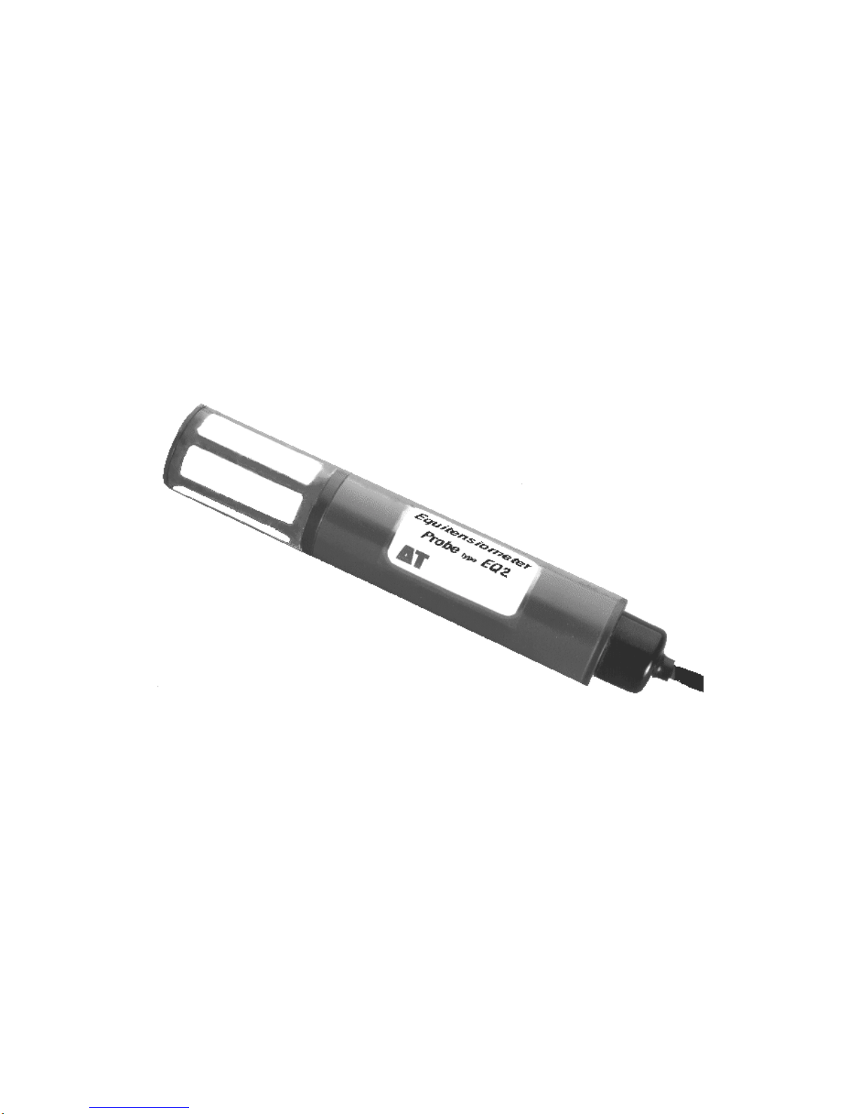
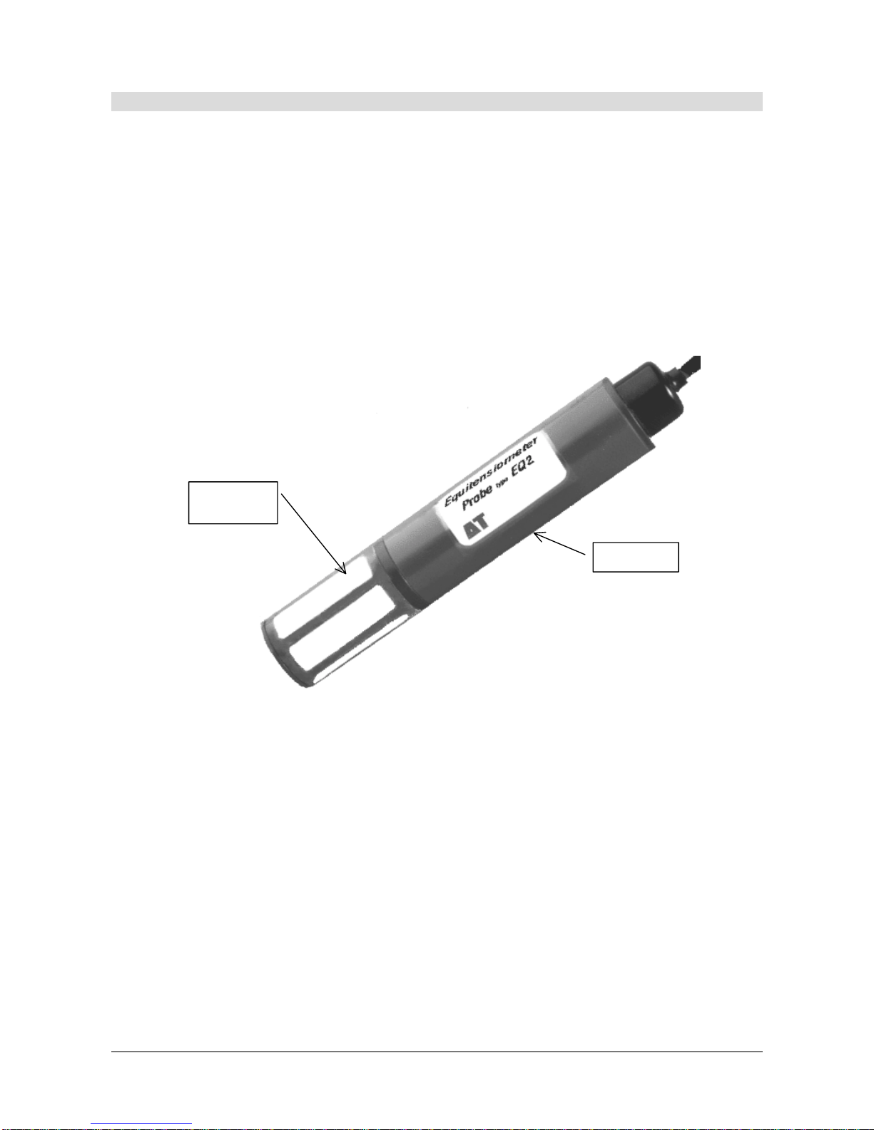
The Equitensiometer consists of a precision soil moisture sensor (the ThetaProbe) whose
measuring rods are embedded in a porous material (the equilibrium body). This material
has a known, stable relationship between water content and matric potential. When the
probe is inserted into the soil, the matric potential within the equilibrium body rapidly
equilibrates to that of the surrounding soils. The water content of the matric material is
measured directly by the ThetaProbe, and this can be converted into the matric potential of
the surrounding soil using the calibration curve supplied with each Equitensiometer.
Figure 1
Equilibrium
body
ThetaProbe

EQ2-UM-1.3 Page 4
Installation
The Equitensiometer should be thoroughly wetted before use, and installed at a horizontal
or slanting angle. Vertical installation may slow the response time, and also lead to
incorrect readings because rainfall running down the side of the probe housing may wet the
soil around the probe excessively. This is particularly important if the probe is being
installed below the soil surface using a probe extension tube. Any gaps between the
Equitensiometer and soil should be filled with quartz powder suspension. Small changes
to the soil structure surrounding the probe will not affect readings.
It is important to protect the Equitensiometer from strong temperature fluctuations and in
particular to avoid exposing the electronics and equilibrium body to different temperatures,
e.g. by installing it with the case in strong sunlight. Avoid flexing the PVC cable at low
temperatures. It is advisable to protect the cable before burying it in conditions where it
may be attacked by soil insects etc.
Soil sampling points
The soil matric potential within a region of soil will be affected by local variations in soil
density and composition, rates of percolation, runoff, evaporation and the uptake of water
by nearby roots. The resultant differences in pressure will equilibrate over time at a rate
which is determined by the local hydraulic conductivity.
It is important to take the degree of variability of these various parameters into account
when deciding on the number of probes to use at any particular location. In particular, if
the soil is known to be very heterogeneous, or the distribution of roots is very non-uniform,
it will be necessary to take measurements from at least three closely-spaced locations.
Extension tubes
Optional extension tubes can be fitted to enable easier withdrawal, and to protect the cable
from damage by animals, etc. Two lengths are available. ML/EX50 is 50cms long and
ML/EX100 is 100cms long. These can be screwed into each other to make longer lengths,
as required. The outside diameter of the extension tubes is 4cms, so an auger of
approximately 5cms is recommended.
Instructions for adding extension tubes:
Carefully remove the black plastic, thread protection cover from the Equitensiometer. This
cover protects the extension tube mating thread when extension tubes are not needed. It can
be removed by sliding it up the cable.
Pass the Equitensiometer cable through the hole in the extension tube, ensuring that the
female thread in the extension tube is towards Equitensiometer. Screw the extension tube
onto Equitensiometer and hand tighten only. Repeat this process for additional extension
tubes to make up the length required.
Finally, thread the cable through the black plastic thread protection cover and slide the
cover into place over the male thread on the end of the extension tube. This will minimise
water ingress into the extension tube.
Frost
The Equitensiometer will withstand frosts, but any readings taken when the water inside
the probe is frozen will be meaningless.

Page 5EQ2-UM-1.3
Connections
Cable Connections
The Equitensiometer is supplied with a four core, screened cable which provides these
connections:
Red Power V+
Blue Power 0V
Yellow Signal HI, (load resistance 10KΩminimum)
Green Signal LO
Braid Cable screen. Not connected within probe.
The Blue and Green leads are connected internally.
The braid screen should be connected to digital ground on the logger or other measuring
unit. If not using Delta-T equipment, please refer to the manufacturer's instructions.
If you simply want to log the probe voltage directly, it can be treated as a differential
voltage source of range 0 - 1.5V DC, and the attached meter or logger should be configured
accordingly.
Warning: use as a single-ended voltage source will introduce measurement errors due
to the sensor power return current and is not recommended.
Some Equitensiometer variants have a connector fitted in order to mate to the appropriate
Delta-T instrumentation. Connection details are given in the relevant instrumentation User
Manual.
Electromagnetic Compatibility ( EMC )
The Equitensiometer has been assessed for compatibility under the European Union EMC
Directive 89/336/EEC and conforms to the appropriate standards, provided the moisture
measuring rods and probe body are completely immersed in the soil or other material being
measured. The cable connecting the Equitensiometer to its associated instrumentation
should also be routed along the surface of the soil.
If the probe is not installed in this way, some interference may be experienced on nearby
radio equipment. Under most conditions, moving the equipment further from
Equitensiometer (typically 1-2 metres) will stop the interference.
Equitensiometers installed near to each other will not malfunction due to interference.
Power supply and warm-ups
The Equitensiometer requires a power supply of 5 to 15V DC at approximately 20mA. For
complete stability, a warm-up time of 5s is recommended, although good repeatability can
be achieved using a 1s warm-up.
Battery power consumed by a probe for a single measurement taken with a 5 second warm-
up time is typically: 20mA * 5s ≅0.03mA.h

EQ2-UM-1.3 Page 6
Connection and configuration for Delta-T loggers (DL2 & DL3000)
Equitensiometers can be directly powered by Delta-T loggers using their internal batteries.
However, if several probes are to be used, or if the logger has to supply significant power
to other sensors or accessories, we recommend powering the logger and sensors from an
external power supply. Although the probe can be continuously powered, significant
power can be saved by using a warm-up relay to energise the sensor just before and during
a log.
The DL2e and DL3000 loggers include a minimum of two relay-controlled outputs to
provide and control sensor power. Each relay is capable of switching 1A, which means that
each logger can power 60 Equitensiometers provided they are the sole warm-up relay
contact load.
DL2e connection and configuration
This diagram shows the connections
for an Equitensiometer connected to
channel 1 of a DL2e in differential
mode, and powered through the
loggers internal power supply.
Further details can be found in the
SENSORS.TXT file, which is supplied
with the DL2e sensor codes for the
Equitensiometer, and in the DL2e
user manual in the Relay Channels
section.
Two sensor configuration codes are
supplied with the DL2e: E2D is intended for linearising the full range of EQ2 output (0 to
-1000kPa), and E2W which provides more resolution at the wet end only (0 to -350kPa).
You will need to enter the individual linearisation table values attached to the calibration
data that is supplied with each of your Equitensiometers.
DL3000 connection and configuration
Full details, including example connection diagrams, are available in the online help
provided with Acquire!. The DL3000 can accept linearisation tables with unequal step
sizes, so you can enter the calibration table exactly as supplied, and the DL3000 will then
linearise to full resolution over the full range.
Note: each Equitensiometer needs its own linearisation table.
Operational considerations
Hysteresis and response time effects
The Equitensiometer only reads correctly once the equilibrium state within the probe is
reached. Normally there is a time lag between the change of matric potential of the
surrounding soil and the response of the Equitensiometer. This time lag is greatest when
the matric potential is changing fast, and at large (negative) matric potentials, see Table 1.
Under natural conditions, changes in matric potential are normally less than 0.01 kPa/min,
so the associated errors will therefore be much lower than the values in Table 1. As shown

Page 7EQ2-UM-1.3
in Fig. 3, in both the wetting and drying phases the time lag is similar to that for transducer
tensiometers.
Table 1: Hysteresis of the Equitensiometer in a rapid drying test. The values are much
higher than under natural conditions.
Matric potential, absolute changes
kPa kPa/min
Errors in kPa after minutes
0 10 30 60 120 180 300 360
-98 -.11 2.2 0.3 0 0 0 0 0 0
-215 -.15 5.6 5.3 2.6 0 0 0 0 0
-376 -.37 20.2 19.1 18.0 16.2 13.5 10.1 3.4 0
Soil properties and salinity
The Equitensiometer is unaffected (not damaged) by physical soil properties (organic
matter, stones, bulk density,) and most chemical soil properties (e.g. pH). No tests have
been carried out in saline soils, so the performance of the Equitensiometer in saline soils is
unknown.
Temperature
The output of the Equitensiometer is slightly dependent on temperature. The Calibration
certificate gives values correct at 20°C. For regions with strong temperature variations, the
following temperature correction should be applied.
() () ()
ù
ê
ë
é−°
−= 420
__ Cetemperatur
mVvaluemeasuredmVvalueCorrected
The Equitensiometer will not be damaged by frost, but its sensitivity to ice is very much
less than water, so any measurements taken below freezing will be meaningless.
Maintenance
Large concentrations of Sodium ions may affect the calibration curves. If the equilibrium
body becomes contaminated, the sodium may be washed out by repeatedly wetting it in de-
ionised water, and then drying it out by inserting it into dry non-saline soil. Washing with
water does not help, because in that case no exchange of water or solute takes place.
The calibration should be stable for ~2 years. It can be checked by putting the probe into
de-ionised water and checking the reading against the 0 kPa value in its calibration table -
at 20°C the reading should be within ± 20 mV. If re-calibration is required the probe will
need to be returned to Delta-T Devices.
No other maintenance is required.

EQ2-UM-1.3 Page 8
Specifications
112 68
40
30
Measurement parameter Matric soil water potential.
Measurement range 0 to -1000 kPa (-10 bar).
Accuracy ±10 kPa from 0 to -100 kPa,
±5% of reading from -100 to -1000 kPa.
Hysteresis not detectable if the change of matric potential is slower
than 0.1 kPa/min.
Soil types Suitable for all non-saline soil types.
Protection Electronics sealed to IP68 (to 5m), all exposed parts
suitable for long-term burial.
Temperature 0 to 40 °C. (Not damaged by use in frozen soils, but
readings will be incorrect)
Power supply 5 to15 V DC, 20 mA typical, 1 s stabilisation.
Output signal approximately 150 to 550 mV, non-linear.
(Calibration data and graph supplied with each sensor)
Dimensions Diameter: 40 mm, Length: 210 mm.
Cable length Standard: 5 m, Maximum: 100 m.

Page 9EQ2-UM-1.3
Definitions
Soil Matric Potential
Studies of plant growth need to characterise the availability of water to the plant, and this
is usually done using the water potential, Ψ, which measures the suction necessary to
extract water from the soil, and has units of pressure, kPa. Components of this water
potential are contributed by gravity, atmospheric pressure, osmosis, and the capillary
action of the soil particles. This last component, called the Soil Matric Potential, ΨM , is
highly dependent on the wetness of the soil, and varies from 0 kPa at field capacity, down
to approximately -1500 kPa at the permanent wilting point.
Soil Water Content versus Soil Matric Potential
The relationship between soil matric potential and soil water content is called the soil
water release curve (it seems to have about 5 other names as well). It differs
enormously form one soil to another, particularly from clay soils at one extreme to sandy
soils at the other. There is no generalised method of converting from soil water content to
matric potential, though a number of expressions have been found which have been
successfully applied to a restricted list of soil types, see for example references 2.
References
1. Gaskin, G.J., and J.D. Miller. 1996. Measurement of soil water content using a
simplified impedance measuring technique. J. agric. Engng Res. 63: 153-160
2. Campbell, G.S. 1974. A simple method for determining unsaturated conductivity
from moisture retention data. Soil Sci. 117:311-314

EQ2-UM-1.3 Page 10
Guarantee, repairs and service
Our Conditions of Sale ref: COND/91/11 set out Delta-T's legal obligations on these
matters. For your information the following paragraphs summarise Delta-T's position but
reference should always be made to our Conditions of Sale which prevail over the
following explanation.
Instruments supplied by Delta-T are guaranteed for one year against defects in manufacture
or materials used. The guarantee does not cover damage through misuse or inexpert
servicing, or other circumstances beyond our control.
For the UK this means that no charges are made for labour, materials or return carriage for
guarantee repairs.
For other countries, the guarantee covers free exchange of faulty parts during the guarantee
period.
Alternatively, if the equipment is returned to us for guarantee repair, we make no charge
for labour or materials but we do charge for carriage and UK. customs clearance.
We strongly prefer to have such repairs discussed with us first, and if we agree that the
equipment does need to be returned, we may at our discretion waive these charges.
SERVICE AND SPARES
We recognise that some users of our instruments may not have easy access to technically
specialised backup.
Spare parts for our own repairable instruments can be supplied from our works. These can
normally be despatched within 1 working day of receiving an order.
Spare parts and accessories for sensors not manufactured by Delta T, but supplied by us
individually or as part of the weather station or other system, may be obtained from the
original manufacturer. We will endeavour to obtain parts if requested, but a certain amount
of additional delay is inevitable.
Should it prove necessary, instruments may be returned to our works for servicing. We
normally expect to complete repairs of our own instruments within 2 days of receiving the
equipment. Other manufacturers' sensors supplied by us and returned for servicing will
take longer. They will have to be returned to the original manufacture for servicing, and
may be subject to additional delays of two to four weeks.
Users in countries that have a Delta-T Agent or Technical Representative should contact
them in the first instance.

Page 11 EQ2-UM-1.3
Sample Calibration Data Sheet
EQ2
interpolation of calibration
values for DL2e sensor tables
calibration values serial No EQ2 9/1
values in the mV column step size
(kPa) step size
(kPa)
used to calc. Interpolated
tables 10 50
original calibration table interpolated
table interpolated
table
"as
supplied" WET range FULL range
Output
(mV) Matric Potential
(-kPa) mV Matric
Potential (-
kPa)
mV Matric
Potential (-
kPa)
420 0 420.0 0 420.0 0
411 10 411.0 10 374.0 50
402 20 402.0 20 305.0 100
383 40 392.5 30 198.0 150
365 60 383.0 40 170.0 200
346 80 374.0 50 161.0 250
305 100 365.0 60 152.0 300
198 150 355.5 70 146.0 350
170 200 346.0 80 140.0 400
152 300 336.5 90 138.0 450
140 400 305.0 100 136.0 500
132 600 283.6 110 134.0 550
129 1000 262.2 120 132.0 600
240.8 130 131.6 650
219.4 140 131.3 700
198.0 150 130.9 750
192.4 160 130.5 800
186.8 170 130.1 850
181.2 180 129.8 900
175.6 190 129.4 950
170.0 200 129.0 1000
168.2 210
166.4 220
164.6 230
162.8 240
161.0 250
159.2 260
157.4 270
155.6 280
153.8 290
152.0 300
150.8 310
149.6 320

EQ2-UM-1.3 Page 12
Full range
-1000
-900
-800
-700
-600
-500
-400
-300
-200
-100
00.0 50.0 100.0 150.0 200.0 250.0 300.0 350.0 400.0 450.0
EQ2 output (mV)
Matric Potential (kPa)
Matric Potential (kPa)
Wet range
y = -25.85E-12x6+ 46.55E-9x5- 34.52E-6x4+ 13.50E-3x3- 2.94E+0x2+ 338.57E+0x - 16.28E+3
-400
-300
-200
-100
00.0 50.0 100.0 150.0 200.0 250.0 300.0 350.0 400.0 450.0
EQ2 output (mV)
Matric Potential (kPa)
Matric Potential (kPa)
polynomial curve fit
Table of contents
Other Delta-T Accessories manuals


Popular Accessories manuals by other brands


Endress+Hauser
Endress+Hauser Proline 800 Brief operating instructions

Vehicle Weighing Solutions
Vehicle Weighing Solutions AIR WEIGHER M350S Quick setup guide

Sonotec
Sonotec Airborne Sound Sensor BS10 operating manual

BEA
BEA R2E-100 user guide

LEGRAND
LEGRAND DT-300 installation instructions

Honeywell
Honeywell PRO 2000 Series Product data


