Delta-T SM150T User manual

User Manual for the
SM150T
Soil Moisture Sensor
Delta-T Devices Ltd

Notices
Copyright
All parts of the SM150T design and documentation are the exclusive right of
Delta-T Devices and covered under copyright law.
Copyright © 2016 Delta-T Devices Ltd.
Patents
The SM150T is protected under international law by the following
patents:-
USA: Patent US7944220
Europe: Patent EP1836483
Australia: Patent AU2005315407
China: Patent CN101080631
EMC Compliance
See page 38.
Design changes
Delta-T Devices Ltd reserves the right to change the designs and
specifications of its products at any time without prior notice.
User Manual Version: SM150T-UM-0.f Nov 2016
Delta-T Devices Ltd
130 Low Road, Burwell
Cambridge CB25 0EJ
UK
Tel: +44 1638 742922
Fax: +44 1638 743155
email: sales@delta-t.co.uk
web: www.delta-t.co.uk

SM150T User Manual 1.0 Introduction 3
Contents
Introduction 5
Description 5
Features 5
Dimensions 6
Parts list 7
Care and Safety 8
How the SM150T works 9
Operation 10
Cable Connections 10
Installation 11
HH150 Meter 12
HH2 Meter 13
Logger connections and configuration 14
GP1 Logger 14
GP2 Logger Controller 15
DL6 Logger 16
DL2e Logger 17
Other Data Loggers 18
Logger Grounding 21
Calibration 24
Soil calibration 25
Sensor calibration 27
Soil moisture reading 28
Troubleshooting 30
Technical Reference 33
Specifications 33
Volumetric water content 33

SM150T User Manual 1.0 Introduction 4
Temperature 33
Definitions 39
References 41
Appendix 1 42
Soil-specific Calibration 42
Laboratory calibration for non-clay soils 43
Laboratory calibration for clay soils 46
Appendix 2: 49
The SM150 Temperature Sensor 49
Global warming and climate studies 49
Civil engineering 49
Soil contamination and hydrogeology 49
Agriculture 49
SM150T Temperature Measurement 50
Effect of Temperature on Water Permittivity 52
Resistance to Temperature Lookup Table 53
Technical Support 54
Index 56
SM150T User Manual 1.0 Introduction 5
Introduction
Description
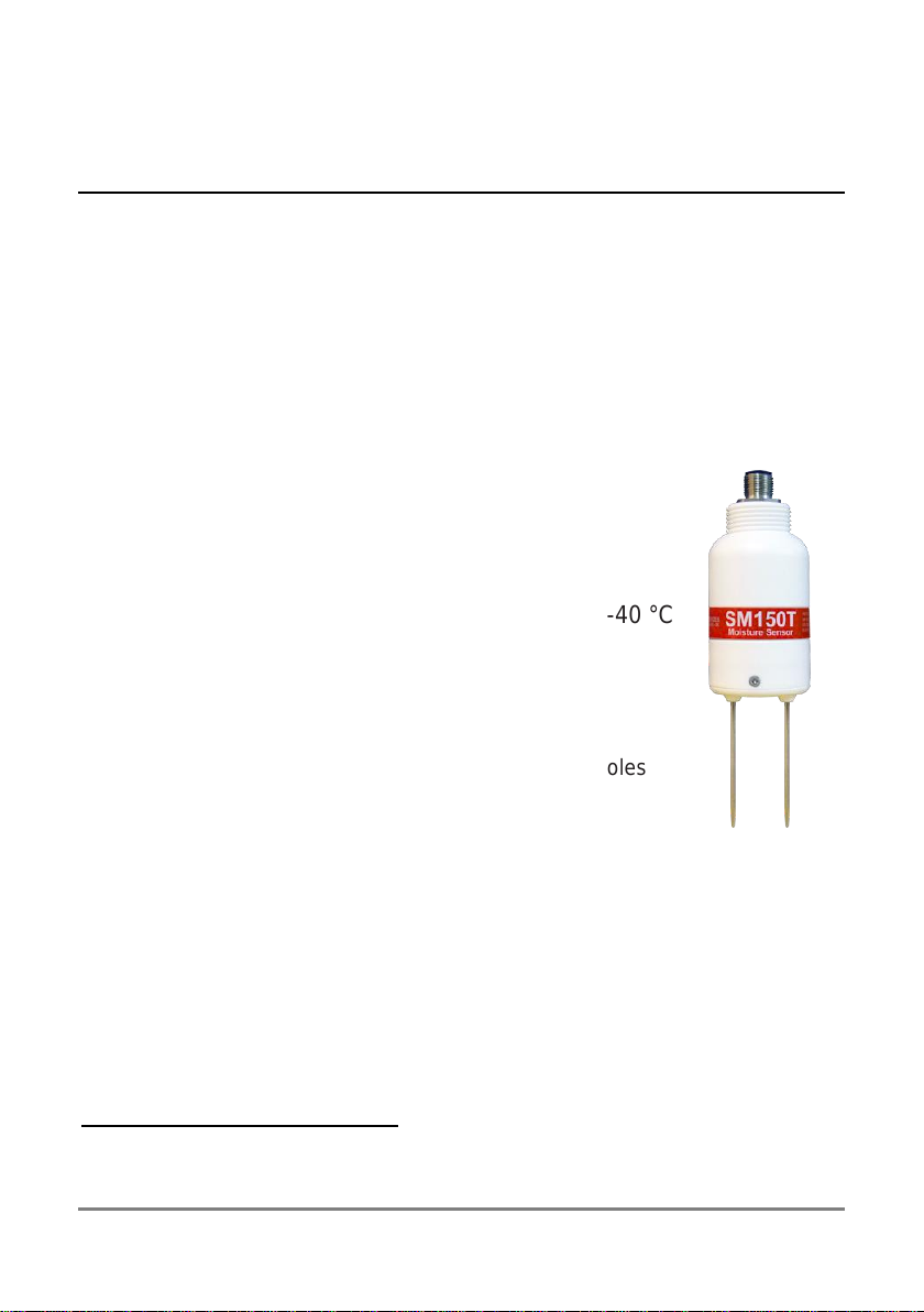
The SM150T measures soil moisture content and temperature.
Its sealed plastic body is attached to two sensing rods which insert directly
into the soil for taking readings.
A waterproof plug connects to a choice of signal cables.
Both extension cables and extension tubes can be used.
The soil moisture output signal is a differential analogue DC voltage. This is
converted to soil moisture by a data logger or meter using the supplied
general soil calibrations.
It can also be calibrated for specific soils.
Features
Soil moisture accurate to ± 3%
Soil temperature to ± 0.5 °C over 0-40 °C
Low salinity sensitivity
Excellent stability
Minimal soil disturbance
Easy installation at depth in augured holes
Waterproof connector to IP68
Rugged, weather-proof and can be buried.
Good electrical immunity
Choice of cabling system options
Cable connector, cylindrical profile and extension tube design
simplifies removal for servicing
Dedicated HH150 meter kit for simple readings
1
HH2 meter1, GP1, GP2, DL6 and DL2e logger compatible
See also Specifications on page 33
1
Does not read temperature

SM150T User Manual 1.0 Introduction 6
Dimensions
Cable connector
sealed to IP68
M12, 5 pin, male
Thread ¾inch BSP
for connecting to
Extension Tube(s)
67 mm
92 mm 51mm
22mm
12
40 mm

SM150T User Manual 1.0 Introduction 7
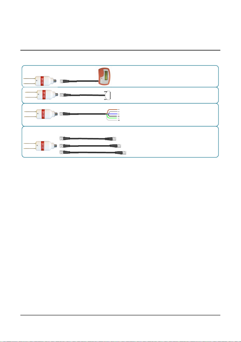
Parts list
Your shipment may include the following:
ML/EX50 50cm
ML/EX100 100cm
SM-AUG-100 Spiral Auger 1.2m
Extension tubes
HH150 +SM150T Kit
SM150T soil moisture sensor
SMCS/d-HH2 0.9m cable
Connects SM150 to HH2
HH150 includes 1m cable,
Connects to SM150T
SMSC/lw-05 5m cable
200mm flying leads
Connect to data logger
EXT/5W-05 5m
EXT/5W-10 10m
EXT/5W-25 25m
Logger extension cables
SM150T User Manual 1.0 Introduction 8
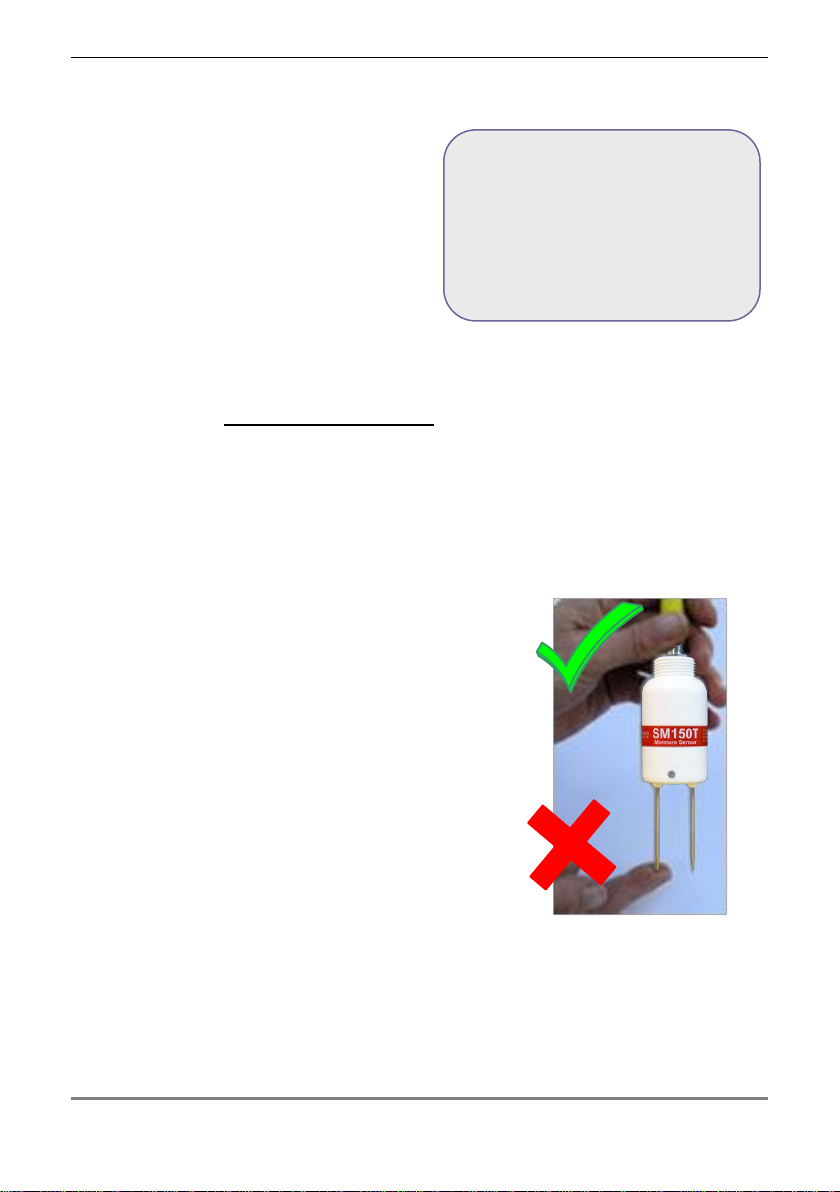
Care and Safety
The rods of the SM150T are sharp in
order to ease insertion. Care must be
taken and handling precautions
followed.
Avoid touching the rods or exposing
them to other sources of static charge,
particularly when powered up.
Keep the SM150T in its protective tube when not in use.
Take care when attaching cables to ensure that the connectors are clean,
undamaged and properly aligned before pushing the parts together.
Do not pull the SM150T out of the soil by its cable.
If you feel strong resistance when inserting the SM150T into soil, it is likely
you have encountered a stone. Stop pushing and re-insert at a new location.
Do not touch the pins, particularly when the
sensor is attached to a cable. An electrostatic
discharge from your body can typically cause a
temporary -10mV offset in sensor readings for
up to one hour. At worse it may permanently
damage the sensor.
To prevent personal injury and damage to the
probe always store and transport the SM150 in
this protective tube
CAUTION
SHARP PINS
Handle with care

SM150T User Manual 1.0 Introduction 9
How the SM150T works
When power is applied to the SM150T...
...it creates a 100MHz waveform (similar to FM radio).
The waveform is applied to a pair of stainless steel rods
which transmit an electromagnetic field into the soil.
The water content of the soil surrounding the rods...
...dominates its permittivity.
an electromagnetic field. Water has a permittivity 81,
compared to soil 4 and air 1)
The permittivity of the soil has a strong influence on the
Vout
SM150T, resulting in a
Soil Moisture
22 %
...acts as a simple, sensitive measure of soil moisture
content.
SM150T User Manual 1.0 Operation 10
Operation
Cable Connections
See also Logger connections and configuration page 14
Take care when attaching cables to ensure that the connectors are clean,
undamaged and properly aligned before pushing the parts together.
Screw together firmly to ensure the connection is water-tight.
Extension cables* can be joined up to a recommended maximum of 100m (for
GP1 or GP2 data loggers) see Specifications on page 33.
*Note: for full accuracy, do not use extension cables with the HH150
** Note The HH150 meter does not record temperature.
SMCS/d-HH2 0.9m cable
Connects SM150 to HH2
HH150 includes 1m cable,
Connects to SM150T
SMSC/lw-05 5m cable
200mm flying leads
Connect to data logger
EXT/5W-05 5m
EXT/5W-10 10m
EXT/5W-25 25m
Logger extension cables

SM150T User Manual 1.0 Operation 11
Installation
Surface installation and spot measurements
Clear away any stones. Pre-form holes in very hard
soils before insertion.
Push the SM150T into the soil until the rods are fully
inserted. Ensure good soil contact.
If you feel strong resistance when inserting the
SM150T, you have probably hit a stone. Stop, and re-
insert at a new location.
Note: The SM150T is not suitable for soil surface
temperature measurements. For soil temperature near the surface dig a
trench and install horizontally as shown below.
Cover both SM150T and the first 30cm of cable with at least 5cm of soil.
Installing at depth
Make a 45mm diameter hole, preferably at about 10°
to the vertical using the SM-AUG-100 auger.
Connect an extension tube e.g. ML/EX50
Push the SM150T into the soil until rods are fully
inserted. Ensure good soil contact.
Alternatively
Dig a trench, and install horizontally.

SM150T User Manual 1.0 Operation 12
HH150 Meter
Connect the SM150T to the HH150 meter.
With the meter OFF, press the right Off –
menu button. This wakes and allows you to
set the meter to display readings - as %
volumetric water content of either Mineral,
Peat Mix, Coir, Mineral Wool or Perlite soils, or
to show the sensor output in Volts.
Press the left on –read button to take a reading.
Repeat as required. You may wish to write down the readings.
Note: The HH150 meter does not record temperature.
Turn on, take
and display
reading
Turn on, show
current setting
OFF
Mineral
32.2%vol
Read
Mineral
▼
Mineral
34.3%vol
OFF
Read
Peat mix
▼
Coir
▼
Min.wool
▼
Perlite
▼
Read
Volts
▼

SM150T User Manual 1.0 Operation 13
HH2 Meter
This assumes you have version 2.8 or later for both the PC
software HH2Read and the HH2 firmware (see foot of page).
Connect the SM150T to the HH2 meter.
Press Esc to turn the meter on, and if necessary press
again until the HH2 displays the start-up screen.
Set the meter to read from an SM150T:
Press Set and scroll down to the Device option.
Press Set again and scroll down to select
SM150T.
Press Set to confirm this choice.
Make sure the HH2 is correctly configured for your soil type:
At the start-up screen, press Set and scroll down to the Soil Type option.
Press Set again and scroll down to the
appropriate soil type (use Mineral for sand,
silt or clay soils or Organic for peaty soils)
Press Set to confirm this choice.
Choose the units in which you want to display the readings.
At the start-up screen, press Set and scroll down to the Display option.
Press Set again and scroll down to select units.
Press Set to confirm this choice.
Press Read to take a reading.
Press Store to save or Esc to discard the reading.
Remove the SM150T from the soil and move to a new location...
If you have saved data, connect your HH2 to a PC and run
HH2Read to retrieve the readings.
For an upgrade contact Delta-T.
See also: HH2 User Manual v4.2 or later
Note: The HH2 does not read temperature
Device: SM150T
Soil Type:
Mineral
SM150T Store?
20.3%vol
SM150T User Manual 1.0 Operation 14
Logger connections and configuration
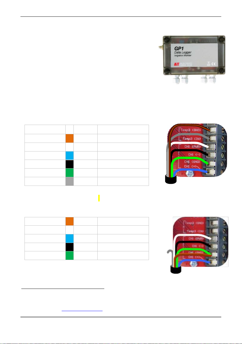
GP1 Logger
Two SM150Ts can connect to each GP1.
Each soil moisture sensor is wired as a differential,
powered sensor.
Requirements
GP1 logger (with v1.48 firmware or later)
PC running DeltaLINK (version 3.6 or later)
SM150T with SMSC/lw-05 cable
Channel 1 and 2 wiring
SM150T wire
Colour
GP1 terminal
Power 0V
brown
CH1/2 (GND)
Power V+
white
CH1/2 (PWR)
Signal HI
blue
CH1/2 (+)
Signal LO
black
CH1/2 (-)
Cable shield
green
CH1/2 (GND)
Temperature +
grey
Temp3 (IN)
Using the DeltaLINK
2
logger software, configure channel 1 or 2 as soil
moisture sensor type SM150T channel 3 or 4 as SM150T Temperature.
Two more SM150T sensors can be added, to Temp3 and/or Temp4 channels
to measure soil moisture -if temperature readings are not required:
Power 0V
brown
CH1/2 (GND)
Power V+
white
CH1/2 (PWR)
Signal HI
blue
CH1/2 (+)
Signal LO
black
CH1/2 (-)
Cable shield
green
CH1/2 (GND)
See also GP1 Quick Start Guide v4 or later and the
DeltaLINK on-line Help.
2
You need the PC logger software DeltaLINK version 3.6 or later. A free upgrade can
be obtained from www.delta-t.co.uk or from the Software and Manuals DVD.
SM150T User Manual 1.0 Operation 15
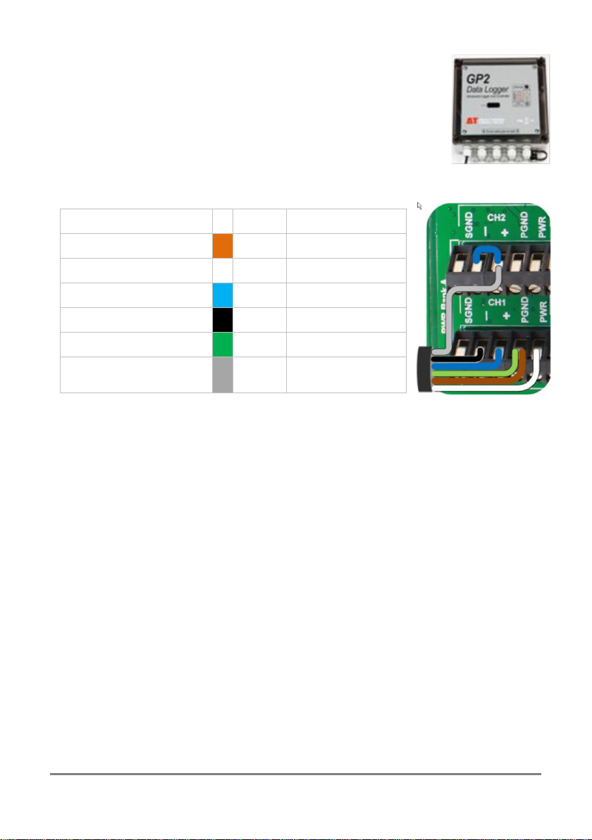
GP2 Logger Controller
Up to 6 SM150Ts can connect to a GP2.
Up to 12 can be connected if not using the temperature sensor.
If using more than 9 you need expansion lid GP2-G5-LID
These details illustrate connection to Channels 1 and 2:
SM150T wire
Colour
GP2 terminal
Power 0V
brown
CH1 (PGND)
Power V+
white
CH1 (PWR)
Soil Moisture Signal HI
blue
CH1 (+)
Soil Moisture Signal LO
black
CH1 (-)
Cable shield
green
CH1 (PGND)
Thermopile HI
grey
CH2(+) and CH2(-)
Fit wire link
For configuration details see the DeltaLINK software sensor Info Panel and
Help or the GP2 User Manual.
Configure each soil moisture channel as sensor type SM150T and configure
the temperature channel as sensor type SM150T Temperature.
SM150T User Manual 1.0 Operation 16
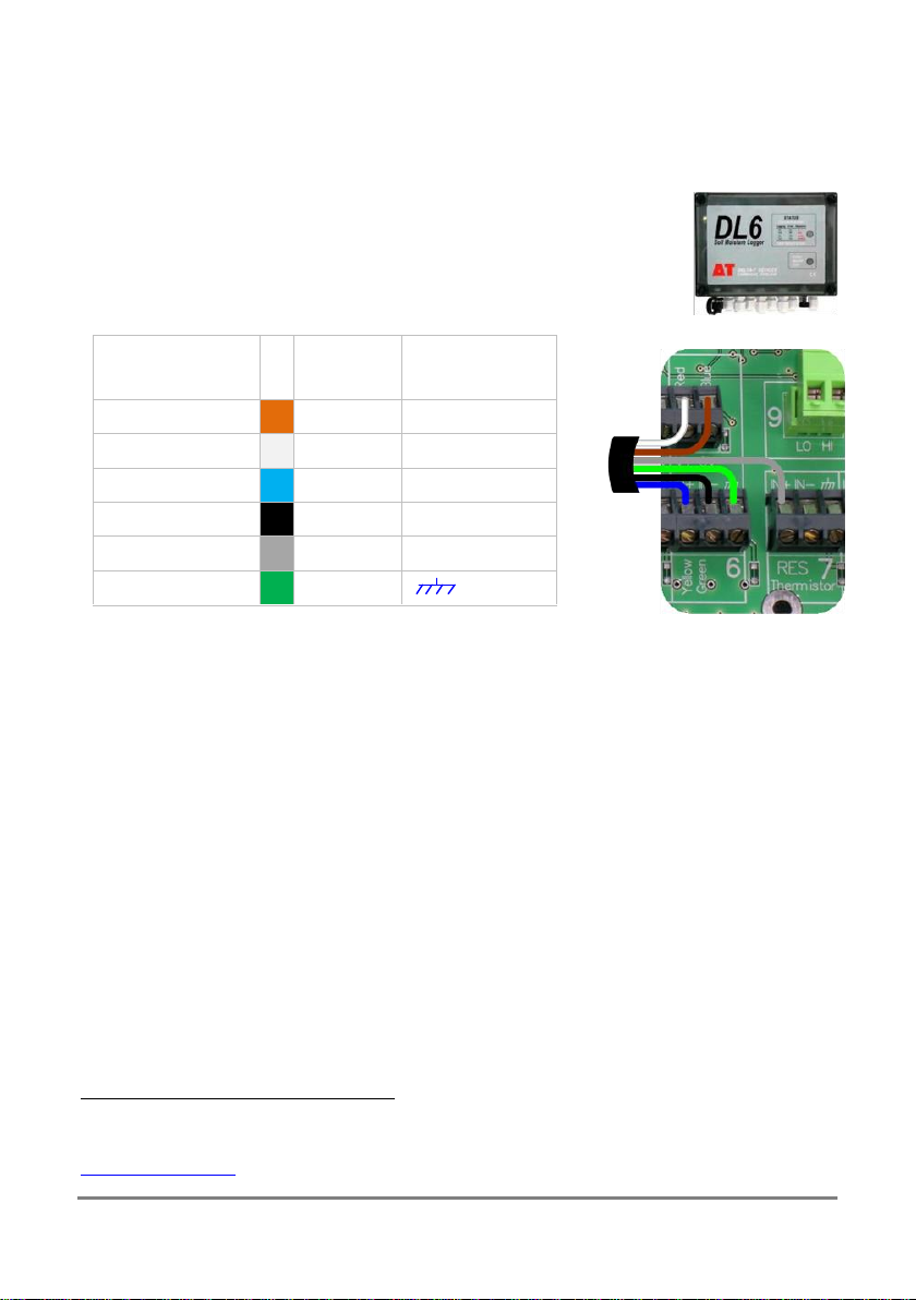
DL6 Logger
6 SM150Ts can be connected to a DL6.
Each soil moisture sensor is wired as a differential, powered sensor.
A DL6 logger can only read one SM150T temperature sensor.
These details illustrate connection to channels 6 & 7:
SM150T
wiring
Colour
DL6
terminal
Power 0V
brown
0V
Power V+
white
V+
Signal HI
blue
IN+
Signal LO
black
IN-
Temperature +
grey
RES IN+
Cable shield
green
In DeltaLINK
3
configure channel 1 - 6 as Moisture Probe SM150T and
channel 7 as SM150T Temperature.
See also the DL6 Quick Start Guide and the DeltaLINK online Help.
3
You need the PC logger software DeltaLINK version 3.6 or later obtainable online at
www.delta-t.co.uk or from the Software and Manuals DVD
SM150T User Manual 1.0 Operation 17
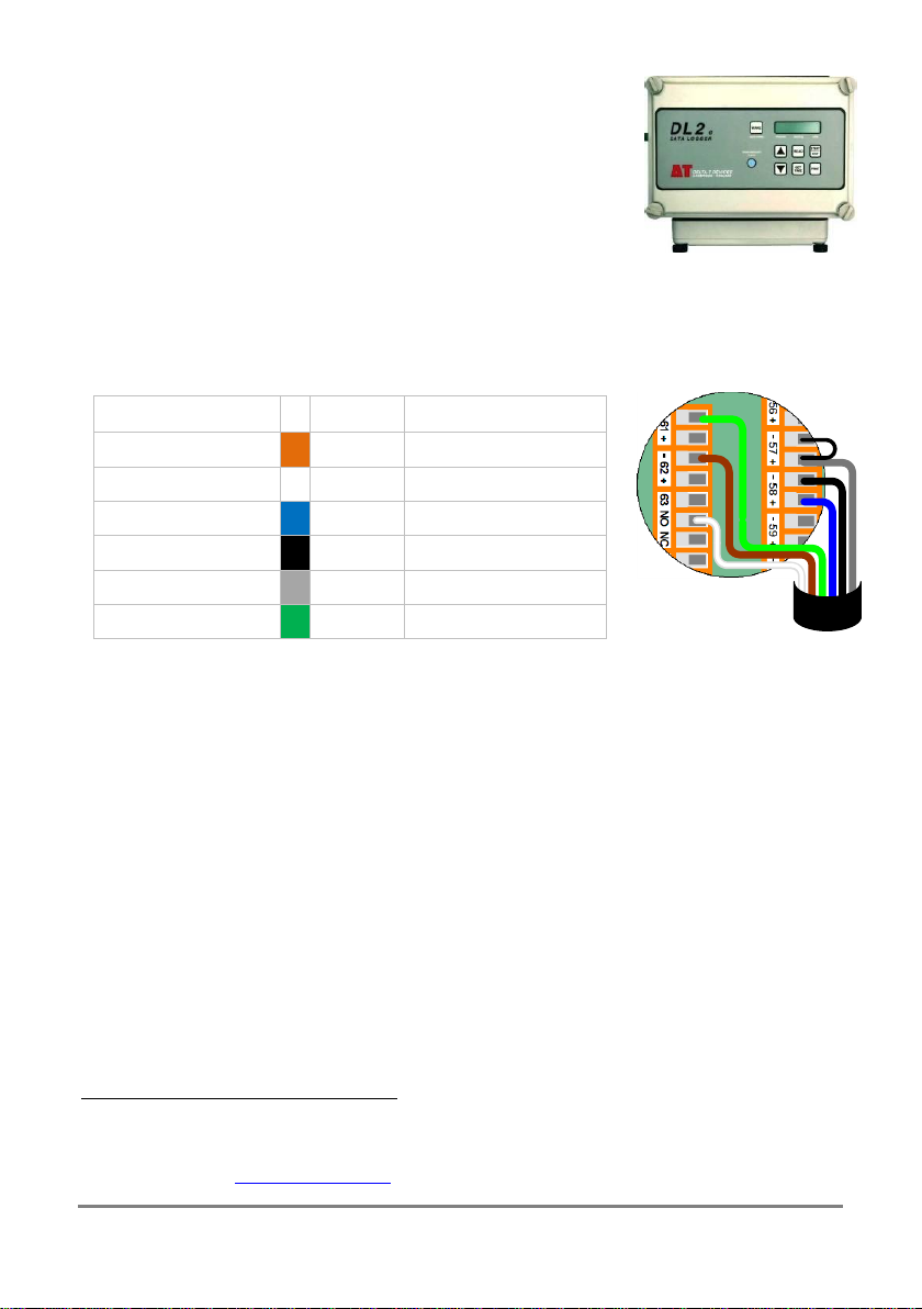
DL2e Logger
Up to 60 SM150Ts can be connected to a DL2e logger
(if not using the temperature sensor channel).
Up to 30 SM150Ts can be connected if also reading the
temperature sensors.
Each moisture sensor is connected as a differential,
powered sensor.
These details illustrate connection to channels 57 and 58 using a LAC1 input
card configured in 15-channel mode, and warm-up channel 63:
SM150T wiring
Colour
DL2e terminal
Power 0V
brown
CH62- or 61-
Power V+
white
CH63 NO
Signal HI
blue
CH58+
Signal LO
black
CH58-
Temperature +
grey
CH57+ and CH57-
Cable shield
green
CH61- or 62-
Note: If using channel 58 ensure the LAC1 card ribbon is attached to the
connector block opposite terminal groups 46-60.
See page 3 of DL2e Quick Start Guide.
Configure the chosen DL2e logger channels by selecting the appropriate
mineral or organic soils listed in the Ls2Win
4
sensor library.
See also the DL2e User Manual and the Ls2Win online help
4
You need a PC running Ls2Win version 1.0 SR10 or later. A free upgrade can
be obtained from www.delta-t.co.uk or from the Software and manuals DVD.

SM150T User Manual 1.0 Operation 18
Other Data Loggers
Connection
SM150T wiring
Description
Wire
colour
Logger connection
Differential connection is preferred
Power 0V
(Power return and
thermistor return)
brown
Power ground/OV
Power return OV
Power V+
(Power supply
voltage)
white
Sensor Power/V+
5-14 VDC, 18 mA, for 0.5 to 1s
Signal HI
(Volumetric water
measurement
signal)
blue
Differential in+/IN+
Or
Signal Input (on single ended loggers)
0-
(±3% vol over 0 to 70% vol and 0-60°C)
(±5% vol over 100 to 1000mS.m-1 and 0-60% vol)
0-
(Reduced accuracy especially at 100%)
See look-up tables and polynomials
Signal LO
(Volumetric water
content return)
black
Differential in-/IN-
Or
0V (On single-ended loggers)
Temperature +
(Thermistor
connection)
grey
Resitance measurement channel
10 K thermistor, ±0.5⁰C over 0-40°C
- See Resistance Lookup
table)
Cable shield
(Noise shield)
green
Low noise 0v (sensor 0v)
(Can use power 0V if sensor 0V not
available)

SM150T User Manual 1.0 Operation 19
The SM150T soil moisture output is best connected as a differential,
powered sensor.
Configure the logger to convert the SM150T readings from milliVolts into
soil moisture units by using either :-
Polynomial conversion below (or on page 28) or
Linearisation table conversion on page 29
5
Note: Output signals in the range 0 to 1.0 volts from the SM150T,
corresponding to ~0 to 60% water content in mineral soils see
Linearisation table conversion on page 29.
Note: The SM150T has been optimised for warm-up of 0.5 to 1 second
duration. It is recommended that the sensor is not powered continuously.
The temperature sensor output should be read as a resistance and the
logger configured with a look-up table to covert the measured resistance
to temperature.
See SM300 Temperature Measurement on page 50
and Resistance to Temperature Lookup Table on page 53.
Logging Advice
Allow 20 minutes for the temperature readings to stabilise after installation
Do not log faster than 1 minute to avoid SM300 self-heating, which could
affect the accuracy of temperature readings.
5
Tables are only available for mineral and organic soils (and temperature).

SM150T User Manual 1.0 Operation 20
Use of polynomial equation to calculates soil moisture
To convert the SM150T output to soil moisture
1) Convert Volts V to using the following equation
Where V is the SM150T soil moisture output converted from milliVolts to
Volts.
2) Convert the value to soil moisture using
Where a0 and a1 are constants:-
For temperature measurement see page 50
a0
a1
Mineral
1.6
8.4
Organic
1.3
7.7
Peat mix
1.16
7.09
Coir
1.16
7.41
Min. wool
1.04
7.58
Perlite
1.06
6.53
Other manuals for SM150T
1
Table of contents
Other Delta-T Accessories manuals


Popular Accessories manuals by other brands

Lanaform
Lanaform Summer Night manual

Dometic
Dometic PERFECTROOF PR2000 operating manual

XBOX
XBOX 9Z4-00001 - 360 Memory Unit Flash Module user guide

SSC-LUXon
SSC-LUXon PALISO Assembly & operating instructions

Bray
Bray 54 Series Installation, operation and maintenance manual

PCB Piezotronics
PCB Piezotronics 352C23 Installation and operating manual


