Delta-T UV3pA User manual
User Manual for the
UV Radiation
Sensors
types UV3pA, B and AB
UV3-UM-1.1
Delta-T Devices Ltd

Notices
Copyright
All rights reserved. Under the copyright laws, this manual may not be
copied, in whole or in part, without the written consent of Delta-T Devices
Ltd. Under the law, copying includes translation into another language.
Copyright © 2000, 2003 Delta-T Devices Limited.
CE conformity
UV3pA, B, and AB
The sensors described in this document are CE marked by the
manufacturer.
Design changes
Delta-T Devices Ltd reserves the right to change the designs and
specifications of its products at any time without prior notice.
User Manual Version: 1.1 August 2003
Delta-T Devices Ltd Tel: +44 1638 742922
128, Low Road, Burwell Fax: +44 1638 743155
CAMBRIDGE CB5 0EJ e-mail: sales
@
delta-t.co.uk
U.K. web: www.delta-t.co.uk

Contents
Introduction 5
Summary of Features 5
Scope of This Manual 5
Installation 6
Unpacking 6
Description of Equipment 6
Mounting the Sensor 7
UV3p Sensor Connections 8
Outline Specs 8
Sensor Wiring 8
Power Requirements 8
Cable 9
Data Requirements 9
UV3p Logger Connections 10
DL2e Logger 10
UV3p Wiring Schematic for DL2e 10
DL3000 Logger 12
Other Loggers 12
Specifications 13
Spectral Response 13
Cosine Response 14
UV3p Specification Table 15
Amplifier characteristics 16
Certification 16
Maintenance 18
Routine Maintenance 18
Recalibration 18
Storage 18
Warranty and Service 19
Terms and Conditions of Sale 19
Service and Spares 20
UV3 User Manual 1.1 Introduction z3


Introduction
Summary of Features
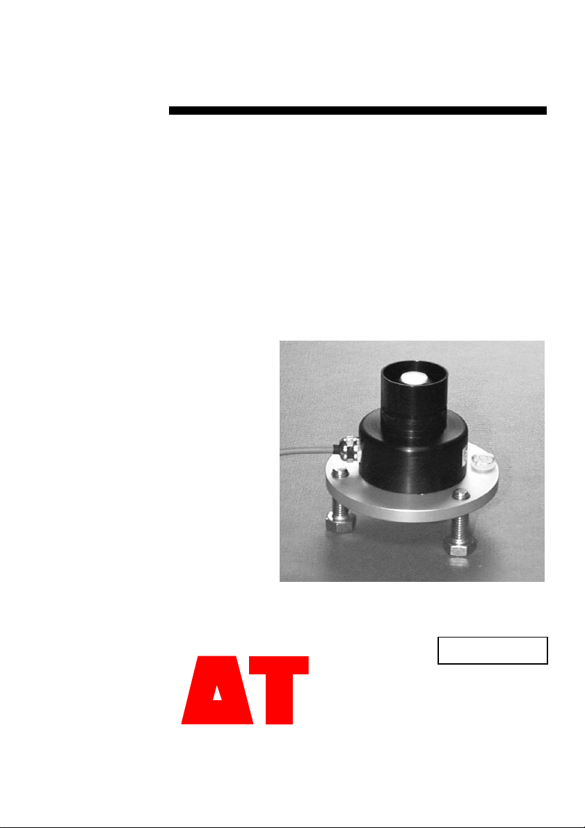
The UV3p sensors are sensitive to ultra-violet radiation. They are
intended for measurements of solar UV of interest to plant scientists and
people involved in environmental monitoring.
The family of sensors covers different parts of the UV region of the solar
spectrum. The B region has traditionally been associated with the most
biological damage, but there is increasing interest in the biological effects
of the lower energy A band. The AB sensor includes both A and B bands.
The sensors incorporate a photodiode detector and transimpedance
amplifier, powered by a single rail power supply. This produces a
standard millivolt output signal that is suitable for data logging.
The sensor can be supplied with an optional levelling mount.
The UV3p sensors are improved versions of the former UV2p sensors,
with the following features:
•Millivolt output with preset, standard sensitivity
•Data logger compatible
•High stability, low temperature coefficient photodiodes
•Self cleaning, stay-dry diffuser with water drainage slots
•Good cosine response with infinity-error correction ring
•All-aluminium body with weather resistant anodising
•Individual sensor calibration and spectral response certificates.
Scope of This Manual
This manual contains the specifications and performance of the UV3pA, B
and AB sensors, and describes their installation with Delta-T data loggers.
You may also need to refer to the appropriate Delta-T logger User Manual
or On-line Help.
UV3 User Manual 1.1 Introduction z5
Installation
Unpacking
Check for any damage that may have occurred to the consignment in
transit. Check that the contents of the consignment agree with the
Packing List.
If any damage or shortage is apparent, notify the agents and the carriers
immediately.
Make a note of the sensor(s) serial number(s), and check that the cable
supplied is the length that was ordered. The serial numbers will be
needed in any subsequent warranty claims, repairs or recalibration.
The parts supplied may include:
•UV3pA, B or AB sensor with cable fitted
•Levelling mount or other mounting bracket
Cable lengths, other than the standard 5m, that are pre-ordered will
normally be fitted in unbroken lengths.
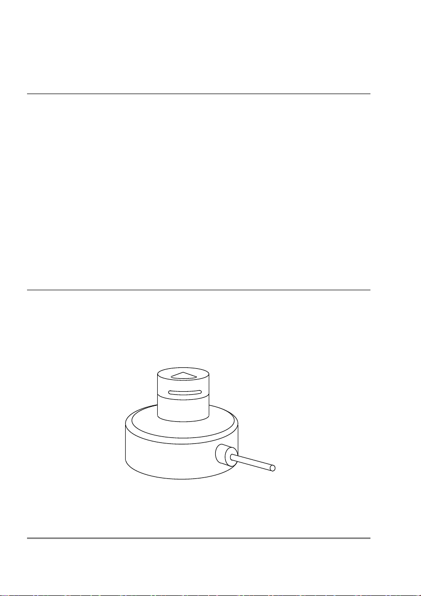
Description of Equipment
Outline Diagrams:
6 zInstallation UV3 User Manual 1.1
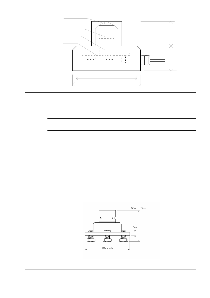
Cosine Diffuser
Photodiode
Filter Glasses
Amplifier
23mm
25mm
43mm
50mm
Mounting the Sensor
M4 mounting screws are provided for the two tapped holes in the base of
each sensor. The mounting holes are at 43 mm spacing.
Warning! Do not use the central hole for mounting the sensor. It is
provided only for factory calibration purposes.
The sensor is usually mounted horizontally for most solar radiation
insolation studies. The readings then give the irradiance (W.m-2) of a
horizontal surface.
A levelling mount is offered as an option, or you can easily make up your
own mounting plate.
If you need to remove excess length of cable at this stage, simply cut off
the excess, but allow for a sufficient length of the cable screen.
Levelling Mount type SRLF1
This is a freestanding platform with adjustable legs and bubble level to
allow the sensor to be accurately mounted horizontally.
UV3 User Manual 1.1 Installation z7

UV3p Sensor Connections
Outline Specs
Parameter Value
Output 1 mV per W.m-2 of radiation in the relevant wave band
Type Waveband
Peak λFWHM*
UV3pA UV A 373 ±2 nm 31 ±2 nm
UV3pB UV B 313 ±2 nm 26 ±2 nm
UV3pAB UV AB 360 ±5 nm 72 ±5 nm
* Full Width Half Maximum
Sensor Wiring
The sensors are fitted with 5m of 4-core screened cable, with bare wire
ends as standard.
Conductor Function Notes
Blue UV Signal HI
Green UV Signal LO Common with Power 0V inside the
sensor. Do not link this wire with Power
0V (yellow). It may create reading
errors.
Red Power V+
Yellow Power 0V
Screen screen Connected to metal body of sensor. Not
connected to any other conductors.
Power Requirements
Power supply 7 - 15 V dc, unstabilised (~2mA)
Power warm up time 10 seconds
8 zUV3p Sensor Connections UV3 User Manual 1.1

Cable
Up to 100m of cable can be fitted at time of ordering.
The UV signal voltage output is not sensitive to the cable length within
this limit.
Data Requirements
Typical common usage:
UV irradiance output Sample every minute.
Average every hour or half-hour.
UV3 User Manual 1.1 UV3p Sensor Connections z9

UV3p Logger Connections
DL2e Logger
Use with LAC1
This diagram shows the wiring connections for the LAC1 analogue input
card. For use with other cards, please refer to the DL2e Logger User
Manual
UV3p Wiring Schematic for DL2e
UV Signal LO (green)
Power V+ (red)
Power 0V (yellow)
Screen
–
61 +
–
62 + 63 NO NC 64 NO NC
–
2 +
–
1 +
–
3 +
–
4 +
–
5 +
BL
R
GN
UV Signal HI (blue)
Y
(or connect to logger frame)
Settings
The example shows the UV3p sensor output connected to analogue
channel number 1 in the DL2e logger.
10 zUV3p Logger Connections UV3 User Manual 1.1

The UV3p is a powered sensor with a low mV output. It should be read
using a differential voltage channel, to avoid possible signal errors that
may occur if connected single-ended.
The LAC1 input card is used in its 15-channel (differential) mode, with the
15-30 slider set to "15".
Power for the UV3p sensor is shown routed through relay channel 63.
Power from the logger’s own battery is connected to terminal 63 using the
internal jumper in the DL2e logger. Alternative sources of power can be
used, if preferred (see the DL2e User Manual).
Note: The cable screen is connected to channel 61- or 62- terminals for
electrical screening purposes. These are the digital earth/frame
connections of the DL2e, and are also used for the Power 0V return.
DL2e Sensor Codes
UV3pA, B or AB
When creating your DL2e logger configuration with the LS2e software,
you can use the UVP sensor code provided.
Warning! Do not use the sensor code “UV” from much earlier releases. It
has a different conversion factor that will give incorrect results if used with
the UV3p sensors.
If you have an earlier release of the LS2e software, you can download the
latest version from the Delta-T web site.
All that remains is to choose suitable sampling and logging intervals (see
data requirements) in your logging configuration.
Relay warm up for powered channels
The UV3p sensor needs power warm-up. Specify one of the relay
channels 63 or 64 and configure it for the warm-up function with a warm-
up time of 10 seconds. This length of time is required for the zero settling
of the sensor amplifier.
UV3 User Manual 1.1 UV3p Logger Connections z11

DL3000 Logger
Wiring Connections and Sensor Types
Refer to the on-line Help related to the former UV2p sensors. It remains
valid for the UV3p sensors. Then select suitable sampling and logging
intervals (see data requirements).
Please consult Delta-T Technical Support if you need further assistance.
Other Loggers
Any logger with a sensitive differential mV input range (e.g. 0 – 50 mV),
and a facility for powering up sensors, can be used for the UV3p range of
sensors.
Follow the general principles laid out above.
12 zUV3p Logger Connections UV3 User Manual 1.1
Specifications
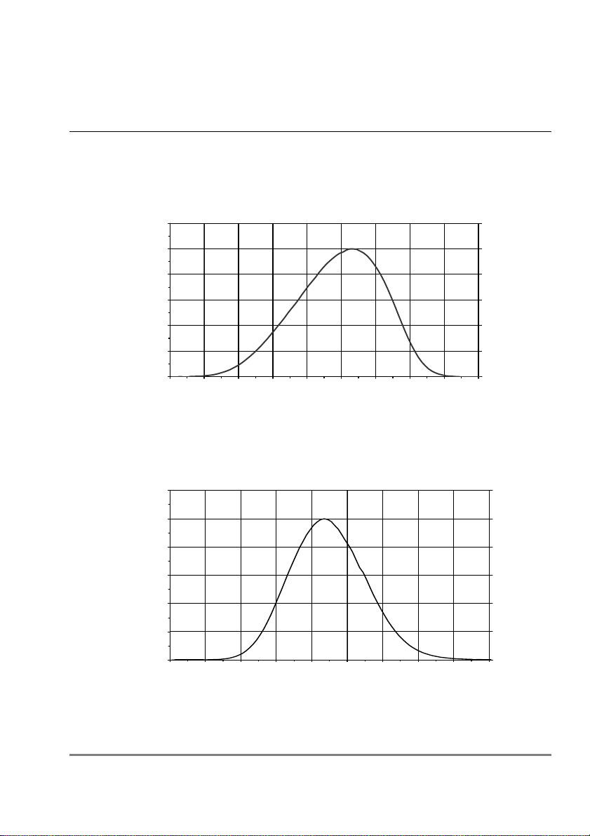
Spectral Response
Figure 1
UV3pA Relative Spectral Response
0
20
40
60
80
100
120
320 330 340 350 360 370 380 390 400 410
Wavelength (nm)
Response
Figure 2
UV3pB Relative Spectral Response
0
20
40
60
80
100
120
270 280 290 300 310 320 330 340 350 360
Wavelength (nm)
Response
UV3 User Manual 1.1 Specifications z13
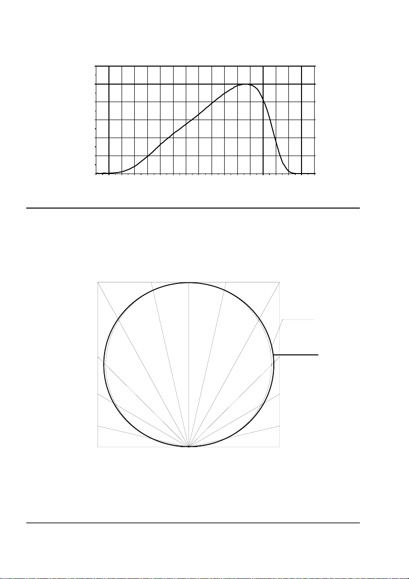
Figure 3
UV3pAB Relative Spectral Response
0
20
40
60
80
100
120
240 250 260 270 280 290 300 310 320 330 340 350 360 370 380 390 400 410
Wavelength (nm)
Response
Cosine Response
Figure 4
True Cosine
60°
30°
UV3p Detector
14 zSpecifications UV3 User Manual 1.1

UV3p Specification Table
Parameter Notes
Photodiode High quality photodiodes:
Si (A, B); GaAsP (AB)
Sensitivity 1 mV per W.m-2 of radiation in the respective
waveband
Wavebands
FWHM
A: 373 ±2nm peak; 31 ±2nm bandwidth
B: 313 ±2nm peak; 26 ±2nm bandwidth
AB: 360 ±5nm peak; 72 ±5nm bandwidth
Accuracy ±7.5% at 20°C
Calibration
traceability
To UK National Physical Laboratory (NPL)
standards
Linearity <1% error
Temperature coeff’t <0.1% per °C typical (Photodiode only. See
below)
Measuring limits
full accuracy
0-150 W.m-2 (A, B)
0-200 W.m-2 (AB)
Cosine corrected Within ±5% up to 70º incidence. See Fig 4
Operating range -20 to 60 °C (A, B);-10 to 60 °C (AB)
Storage range -40 to 60 °C (A, B);-20 to 60 °C (AB)
Voltage supply 7-15 V dc (~2 mA)
Warm up period 10 seconds, recommended
Amplifier type Transimpedance
Amplifier offset drift Typical 0.3 µV per °C. Positive for increasing
temperature. Additional to photodiode error.
Size (mm) 48 high x 50 dia (base)
Weight (excl cable) 125 g
Base mounting Two M4 tapped holes on 43 mm PCD
Finish Black hard anodised
Enclosure rating IP65
Spectral response Individual graph
Cable type 4-core screened, 3 mm dia
Terminations bare wires
Cable length 5 m standard; 100 m maximum
UV3 User Manual 1.1 Specifications z15
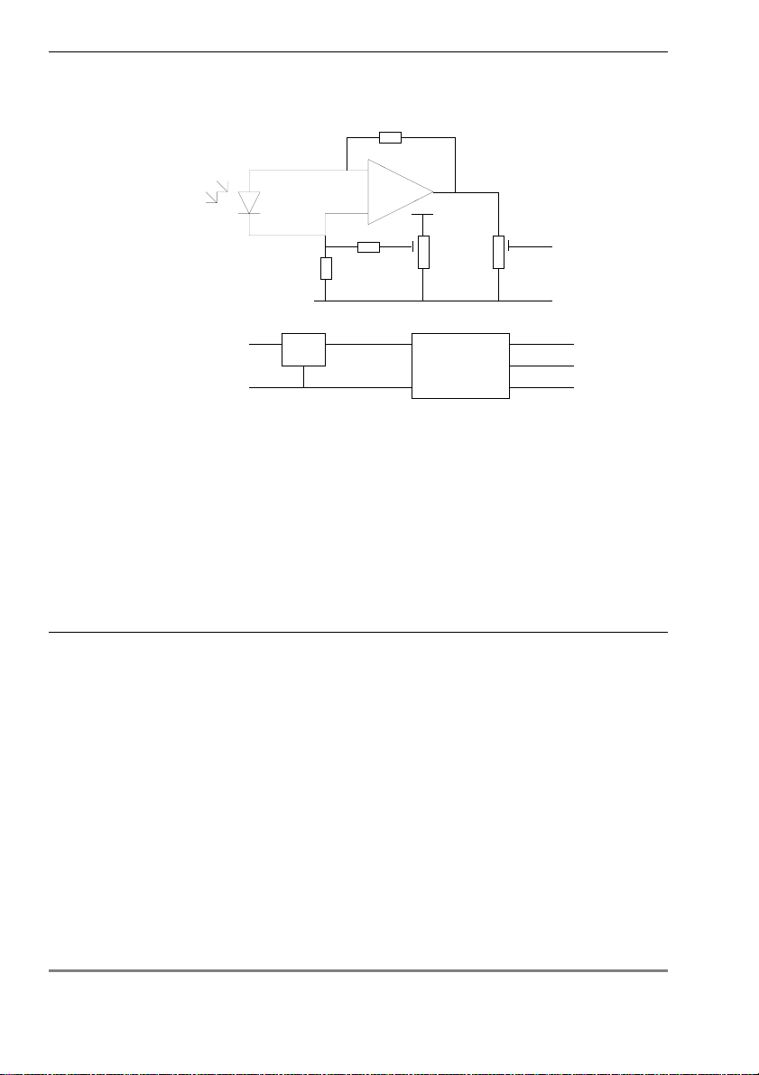
Amplifier characteristics
Schematic
+
-
+V
O/P
7 - 15V
Supply
+5V
-5V
0V
0V
Zero Gain / Cal.
Reg. Invertor
Note that the transimpedance amplifier adjusters and power rails are not
accessible to the user.
The 0V signal output is electrically common with the input Power 0V rail.
Input Offset Drift
Typical +0.3 µV per °C (=0.3 mW.m-2 per °C). Positive for increasing
temperature. This error is in addition to any error contributed by the
photodiode.
Certification
CE Conformity
Delta-T Devices Ltd holds a CE Declaration of Conformity issued by the
manufacturer.
The manufacturer certifies that Ultra-violet detectors with integral
amplifiers model numbers UV3pA, UV3pB and UV3pAB comply with
European directive EMC (89/36/EEC) for Radiated Emissions, Conducted
Emissions, Radiated Immunity and Fast Transients.
16 zSpecifications UV3 User Manual 1.1

Certificate of Calibration
Calibration is carried out under a xenon arc light beam, at normal
incidence to the sensor, by reference to transfer standards.
Individual Calibration Certificates and spectral response graphs are
supplied with each UV3p sensor. The following details are included.
Example
CERTIFICATE OF CALIBRATION
The Manufacturers hereby certify that this instrument has been calibrated
using standards whose accuracy is traceable to the National Physical
Laboratory (NPL Certificate No. 120R11/921011/D18) and the National
Bureau of Standards within the limitations of the NPL’s and the NBS’s
calibration services, or have been derived from known values of physical
contacts.
MODEL: UV3pA
SERIAL NUMBER: 6252/UV3pA-112
CERTIFICATE NUMBER: 7438/2
DATE ISSUED: 22nd June 2000
VALID: 12 months
CALIBRATION DETAILS:
SOURCE: Xenon Arc Lamp (LTE-030)
TRANSFER STANDARD: CAL105A-Cos (LTE-043) @ 373nm
POWER LEVEL: 0.94 W/m2
DETECTOR VOLTAGE: 0.94 mV ± 0.1 mV
SENSITIVITY: 1.0 mV/W/m2
mV = 1.0 W/m2
CALIBRATION NOTES:
Absolute calibration accuracy is ± 7.5%.
Detectors normalised spectral response graphed and supplied.
Definition: 1mV = 1W/m2.
Calibrated By: (Signature) TEST ENGINEER
UV3 User Manual 1.1 Specifications z17

Maintenance
Routine Maintenance
The very low level of UV in solar radiation, and its susceptibility to
absorption by dirt and grease, requires that the UV sensor diffuser be
cleaned regularly. In most cases, weekly cleaning with a soft toothbrush,
clean freshwater and liquid detergent will be sufficient.
Do not remove the base plate screws. There are no user accessible
controls inside.
Recalibration
The calibration certificate validity period is 12 months. Annual
recalibration is essential.
Return the sensor to Delta-T. Contact your agent (or Delta-T direct) in
advance for prices and despatch instructions before returning the unit.
Storage
Observe the storage temperature limitations (see Specifications).
18 zMaintenance UV3 User Manual 1.1

Warranty and Service
Terms and Conditions of Sale
Our Conditions of Sale (ref: COND: 1/00) set out Delta-T's legal
obligations on these matters. The following paragraphs summarise Delta-
T's position but reference should always be made to the exact terms of
our Conditions of Sale, which will prevail over the following explanation.
Delta-T warrants that the goods will be free from defects arising out of the
materials used or poor workmanship for a period of twelve months from
the date of delivery.
Delta-T shall be under no liability in respect of any defect arising from fair
wear and tear, and the warranty does not cover damage through misuse
or inexpert servicing, or other circumstances beyond our control.
If the buyer experiences problems with the goods they shall notify Delta-T
(or Delta-T’s local agent) as soon as they become aware of such problem.
Delta-T may rectify the problem by supplying faulty parts free of charge,
or by repairing the goods free of charge at Delta-T's premises in the UK,
during the warranty period,
If Delta-T requires that goods under warranty be returned to them from
overseas for repair, Delta-T shall not be liable for the cost of carriage or
for customs clearance in respect of such goods. However, we much
prefer to have such returns discussed with us in advance, and we may, at
our discretion, waive these charges.
Delta-T shall not be liable to supply products free of charge or repair any
goods where the products or goods in question have been discontinued
or have become obsolete, although Delta-T will endeavour to remedy the
buyer’s problem.
Delta-T shall not be liable to the buyer for any consequential loss,
damage or compensation whatsoever (whether caused by the negligence
of the Delta-T, our employees or agents or otherwise) which arise from
the supply of the goods and/or services, or their use or resale by the
buyer.
Delta-T shall not be liable to the buyer by reason of any delay or failure to
perform our obligations in relation to the goods and/or services, if the
delay or failure was due to any cause beyond the Delta-T’s reasonable
control.
UV3 User Manual 1.1 Warranty and Service z19

Service and Spares
Users in countries that have a Delta-T Agent or Technical Representative
should contact them in the first instance.
Spare parts for our own instruments can be supplied from our works.
These can normally be despatched within a few working days of receiving
an order.
Spare parts and accessories for sensors or other products not
manufactured by Delta-T, may have to be obtained from our supplier, and
a certain amount of additional delay is inevitable.
No goods or equipment should be returned to Delta-T without first
obtaining the agreement of Delta-T or our agent.
On receipt at Delta-T, the goods will be inspected and the user informed
of the likely cost and delay. We normally expect to complete repairs within
a few working days of receiving the equipment. However, if the equipment
has to be forwarded to our original supplier for specialist repairs or
recalibration, additional delays of a few weeks may be expected.
Troubleshooting
Technical Support
Technical Support is available on Delta-T products and systems. Users in
countries that have a Delta-T Agent or Technical Representative should
contact them in the first instance.
Technical Support questions received by Delta-T will be handled by our
Tech Support team. Your initial enquiry will be acknowledged immediately
with a “T number” and an estimate of time for a detailed reply (normally a
few working days). Make sure to quote our T number subsequently so
that we can easily trace any earlier correspondence.
In your enquiry, always quote instrument serial numbers, software version
numbers, and the approximate date and source of purchase where these
are relevant.
20 zTroubleshooting UV3 User Manual 1.1
This manual suits for next models
2
Table of contents
Other Delta-T Accessories manuals


