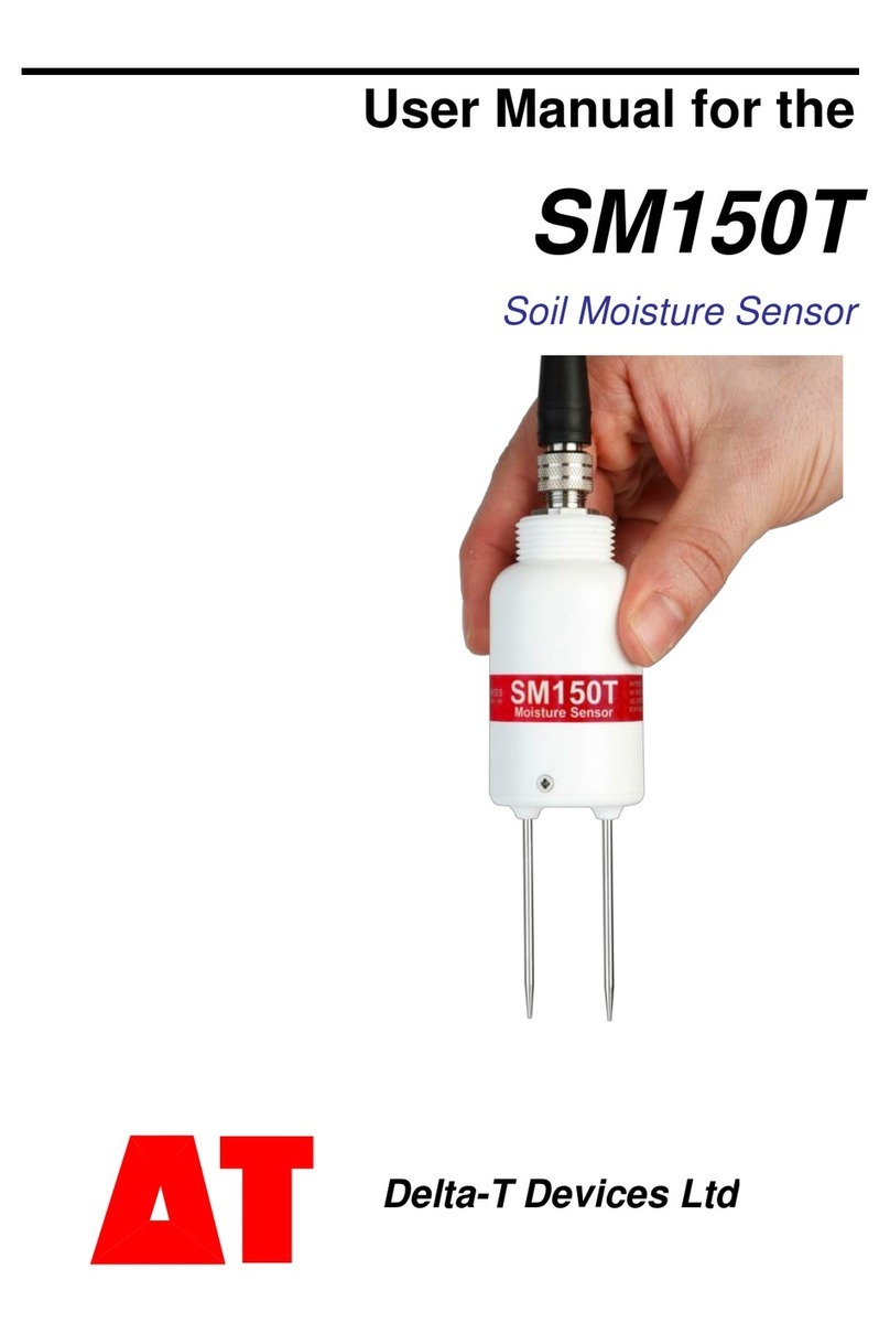
Delta-T SM150T User manual

SM150T
Soil Moisture Sensor
Quick Start Guide
Version4.0
Delta-T Devices Ltd

© 2017 Delta-T Devices Ltd Page 2
SM150T overview
1Cables
2 Installation
4 HH2
5 Data
Loggers
3HH150
Manual readings Manual readings
with memory Automatic readings
with memory

© 2017 Delta-T Devices Ltd Page 3
1Cables and Accessories
Logger Extension cables can be joined up to a maximum length of 100m.
Align connectors carefully before pushing parts together.
Screw together firmly to ensure the connection is water-tight.
Note: HH150 and HH2 meters do not read SM150T temperature.
ML/EX50 50cm
ML/EX100 100cm
SM-AUG-100 Spiral Auger 1.2m
Extension tubes
SM150T soil moisture sensor
SMCS/d-HH20.9m cable
Connects SM150T to HH2
HH150 includes 1m cable,
Connects to SM150T
SMSC/lw-05 5m cable
200mm flying leads
Connect to data logger
EXT/5W-05 5m
EXT/5W-10 10m
EXT/5W-25 25m
Logger extension cables
SM150T + HH150 Kit
SM150T + HH2 Kit
includes SMSC/d-HH2 cable

© 2017 Delta-T Devices Ltd Page 4
2 Installation
Surface installation and spot measurements
◼Clear away any stones.
Pre-form holes in very hard soils before insertion.
◼Push the SM150T into the soil until the rods are fully
inserted. Ensure good soil contact.
◼If you feel strong resistance when inserting the
SM150T, you have probably hit a stone. Stop, and
re-insert at a new location.
Note: The SM150T is not suitable for soil surface
temperature measurements. For soil temperature near
the surface dig a trench and install horizontally as shown below.
Cover both SM150T and the first 30cm of cable with at least 5cm of soil.
Installing at depth
◼Auger a 45mm diameter hole. ~10° to vertical is
recommended.
◼Fit an extension tube to the SM150T –remember to
pass the cable through the extension tube and fit the
connector first.
◼Push the SM150T into the soil until rods are fully
inserted. Ensure good soil contact.
Alternatively
◼Dig a trench, and install horizontally.
Note: Extension tubes are available for installing the
SM150T in an augered hole.

© 2017 Delta-T Devices Ltd Page 5
3 HH150 Meter
◼Connect the SM150T to the HH150 meter.
◼With the meter OFF, press the right off –menu button. This wakes and allows
you to set the meter to display readings - either as % volumetric water content of
Mineral, Peat mix, Coir, Min. wool, Perlite, or show the sensor output in Volts.
◼Press the left on –read button to take a reading.
Repeat as required. You may wish to write down the readings.
The meter will sleep after 30 seconds.
The battery should last for about 10,000 readings.
How to Change Battery
Turn on, take
and display
reading
Turn on, show
current setting
OFF
Mineral
32.2%vol
Read
Mineral
▼
Mineral
34.3%vol
OFF
Read
Peat mix
▼
Coir
▼
Min.wool
▼
Perlite
▼
Read
Volts
▼
Place face down
& remove screws Holding the cable
down against the
front cover -
remove the back
Fit new batteries Replace
back cover
Only use good quality
alkaline batteries
PRESS DOWN
HH150 does not read
SM150T temperature

© 2017 Delta-T Devices Ltd Page 6
4HH2 Meter
Note the HH2 does not read the temperature sensor.
Use version 2.8 or later of both the PC software HH2Read
and the HH2 firmware (see footnote)
◼Connect the SM150T to the HH2 meter.
◼Press Esc to turn the meter on, and if necessary
press again until the HH2 displays the start-up screen.
◼Set the meter to read from an SM150T:
►Press Set and scroll down to the Device option.
►Press Set again and scroll down to select
SM150T.
►Press Set to confirm this choice.
◼Make sure the HH2 is correctly configured for your
soil type:
►At the start-up screen, press Set and scroll down to the Soil Type option.
►Press Set again and scroll down to the appropriate soil type (use Mineral for
sand, silt or clay soils or Organic for peaty
soils)
►Press Set to confirm this choice.
◼Choose the units you want for displaying readings:
►At the start-up screen, press Set and scroll down to the Display option.
►Press Set again and scroll down to select units.
►Press Set to confirm this choice.
◼Press Read to take a reading.
◼Press Store to save or Esc to discard the reading.
◼Remove the SM150T from the soil and move to a new location...
◼If you have saved data, connect your HH2 to a PC and
run HH2Read to retrieve the readings.
Note: For an upgrade contact Delta-T.
See also: HH2 User Manual
Device:
SM150T
Soil Type:
Mineral
SM150T Store?
20.3%vol

© 2017 Delta-T Devices Ltd Page 7
5 Data Loggers
GP2
◼6 SM150Ts can connect to a GP2
12 can be connected if not using the temperature sensors
If using more than 9 you need expansion lid GP2-G5-LID.
These details illustrate connection to Channels 1 and 2:
SM150T wiring
Colour
GP2 terminal
Power 0V
brown
CH1 (PGND)
Power V+
white
CH1 (PWR)
Soil Moisture Signal HI
blue
CH1 (+)
Soil Moisture Signal LO
black
CH1 (-)
Cable shield
green
CH1 (PGND)
Thermopile HI
grey
CH2(+) and CH2(-)
Fit wire link
Configure channel 1 as type SM150T and channel 2 as SM150T Temperature.
See also DeltaLINK* software sensor Info Panel and Help or the GP2 User Manual.
GP1
◼2 SM150Ts can connect to each GP1. Each SM150T is
wired as a differential, powered sensor..
Channel 1 and 3 wiring:
SM150 wiring
Colour
GP1 terminal
Power 0V
brown
CH1 (GND)
Power V+
white
CH1 (PWR)
Signal HI
blue
CH1 (+)
Signal LO
black
CH1 (-)
Cable shield
green
CH1 (GND)
Temperature+
grey
Temp3 (IN)
◼Using DeltaLINK* logger software (version 3.6* or later) configure channel 1 as
SM150T(soil moisture) and channel 2 as SM150T(temperature).
See also GP1 Quick Start Guide and DeltaLINK Help.
* Download the latest version of the DeltaLINK logger software, v3.6 or later, from www.delta-
t.co.uk or from our Software and Manuals DVD

© 2017 Delta-T Devices Ltd Page 8
DL6
◼Up to 6 SM150Ts can connect to a DL6 logger but only one of
the integrated temperature sensors can be connected.
◼Each is wired as a differential, powered sensor.
These details illustrate connection to channel 6 and 7:
SM150T wiring
Colour
DL6 terminal
Power 0V
brown
0V
Power V+
white
V+
Signal HI
blue
IN+
Signal LO
black
IN-
Temperature +
grey
RES IN+
Cable shield
green
◼In DeltaLINK configure channel 1 - 6 as Moisture Probe SM150T and channel 7
as SM150T Temperature.
See also the DL6 Quick Start Guide and the DeltaLINK onlin Help.
* Download the latest version (v3.6 or later) of the DeltaLINK logger software from
www.delta-t.co.uk or from our Softaware and Manuals DVD.
DL2e
◼Up to 30 SM150Ts may be connected (or 60 if not
reading the temperature).
◼Each soil moisture sensor is connected as a differential,
powered sensor.
This example uses channels 57 and 58 with a LAC1 input
card configured in 15-channel mode, and warm-up channel 63.
SM150T wiring
Colour
DL2e terminal
Power 0V
brown
CH62- or 61-
Power V+
white
CH63 NO
Signal HI
blue
CH58+
Signal LO
black
CH58-
Cable shield
green
CH61- or 62-
Temperature +
grey
CH57+ and CH57-
◼Configure the DL2e logger channels by selecting the appropriate SM150T sensor
types from the LS2Win sensor library. Use Ls2Win version 1.0 SR10 or later*.
See also the DL2e User Manual or LS2Win Help.
* Download the latest version of Ls2Win logger PC software from www.delta-t.co.uk or
from our Software and Manuals DVD.

© 2017 Delta-T Devices Ltd Page 9
6 How to calculate soil moisture
Conversion to
Polynomial (for use over the full range of SM150T readings)
.(1)
where V is the SM150T output in volts
Linearisation table (for use over the full range of SM150T readings)
V
V
V
V
V
0.000
1.000
0.300
3.576
0.600
5.101
0.900
6.778
1.200
8.924
0.075
1.942
0.375
3.964
0.675
5.503
0.975
7.232
1.275
9.743
0.150
2.620
0.450
4.337
0.750
5.917
1.050
7.720
1.350
10.808
0.225
3.144
0.525
4.713
0.825
6.342
1.125
8.270
1.425
12.242
Conversion from to Soil Moisture
◼Soil moisture
◼Use these generalised soil calibration values for
mineral and organic soil types, or carry out a soil-
specific calibration to derive your own values
See SM150T User Manual.
◼Multiply x100 to convert soil moisture from
m3.m-3 to % volumetric.
Direct conversion for Mineral and Organic soils
Example
◼Take a reading with the SM150T
V = 0.294 volts
either
◼Convert the reading to
using equation 1 or the
linearisation table below.
= 3.52
◼Then convert
to soil moisture,
, using the soil
calibration values (a0, a1).
= 22.9% for mineral soil
or
◼Convert directly for mineral or organic soils using
equations 2 or 3
= 22.9%
a0
a1
Mineral
1.6
8.4
Organic
1.3
7.7
Peat mix
1.16
7.09
Coir
1.16
7.41
Min. wool
1.04
7.58
Perlite
1.06
6.53

© 2017 Delta-T Devices Ltd Page 10
7 Check Sensor is working
Air reading
◼Hold the SM150T in air and away from other objects and take a reading using an
HH150 meter, or an HH2 meter or voltmeter or a logger with no more than 5m of
cable. In air the reading should be 0 ±4mV
(Note: the HH150 reports under-range if the reading is less than zero )
Warning: Do not touch the pins
Try not to touch the pins. A typical electrostatic discharge from your
body can create a temporary offset in sensor readings for up to one
hour.
Water reading
◼Measure the output in voltage.
In the UK the sensor will typically read about 1.5 volts in tap water (because the
salinity is typically 50mS.m-1).
The “water reading”you get will depend on the salinity of your local water.
Note: HH150 meter indicates “TOO WET” above 1.5V or 85% vol.
Graph: showing the effect of salinity on SM150T sensor output when
fully immersed in water with no soil present.
0.00%
10.00%
20.00%
30.00%
40.00%
50.00%
60.00%
70.00%
80.00%
90.00%
100.00%
0.0
0.2
0.4
0.6
0.8
1.0
1.2
1.4
1.6
1.8
0 100 200 300 400 500 600
Output (%vol)
Output (Volts)
Conductivity ECp(mS.m-1)
SM150 fully immersed in water - as read
by HH150 and HH2 meters
Volts
% vol (mineral)
%vol (organic)
"TOO WET"
Soil moisture
readings are not
correct when no
soil is present i.e. at
100% vol.
SM150T tables and
polynomial
constants are
optimised at 220
mS.m-1 for soil
moisture values
below 70%vol

© 2017 Delta-T Devices Ltd Page 11
8 Specifications (for full specification see SM150T User Manual)
Volumetric Water Content
Accuracy
3.0% vol over 0 to 70 % vol and 0-60°C
Measurement range
0 to 100% vol but less accurate above 70%vol**
Salinity error
5% vol over 100 to 1000 mS.m-1 and 0-60% vol
Conductivity response
See SM150T User Manual
Temperature sensitivity
See SM150T User Manual
Sampling volume
See SM150T User Manual
Output signal
0-1 V differential 0 to 60% nominal
Output compatible with
HH150, HH2, GP1, GP2, DL6, DL2e
Temperature
SM150T must be fully buried to accurately measure soil
temperature
Sensor accuracy
±0.5°C over 0-40°C*
not including logger or cabling error
Output
Resistance: 5.8kΩ to 28kΩ*
Output compatible with
GP1, GP2, DL6* DL2e
Cabling error contribution (to
temperature reading)
0°C for GP1, GP2 & DL6 (any cable length)
0°C for DL2e (with 5m cable).*
Maximum cable length
100m (GP1, GP2 & DL6 data loggers) 100m
(DL2e: water content measurement) 25m (DL2e:
temperature measurement)
Power requirement
5-14VDC, 18mA for 1s
Operating range
-20 to +60°C
Environment
IP68***
Sample volume
55 x 70 mm diameter
Dimensions
143 x 40 mm diameter
Weight
77 gm (without cable)
HH150 meter
does not read SM150T temperature
Accuracy
±7.5mV (negligible effect on SM150 accuracy)
Resolution
0.1% of volumetric reading or 1mV
Battery / life/standby life
2xGP alkaline AAA/ 10000 readings/1 year
Environmental
Non condensing
Compliance
CE, FCC & ROHS
* Note: See full specification in SM150T User Manual
** In water (no soil present) the reading may not be 100% vol.
It depends on a0 and a1 but can still be used as a quick check that the unit is working.
*** With Delta-T supplied cables

Field of sensitivity
This graph shows the effect of being too close to the wall of a plant pot and gives a
partial indication of the shape of the field of sensitivity around the pins
9 Care and Safety
-6%
-5%
-4%
-3%
-2%
-1%
0%
1%
0 5 10 15 20 25 30 35 40
Error (% of reading)
Gap between SM150 body and wall of pot (mm)
SM150T Error close to wall of plant pot.
live pin nearest to pot wall
Delta-T Devices Ltd
130 Low Road
Burwell
Cambridge CB25 0EJ
England (UK)
◼Do not touch the rods or expose them to other sources of static damage,
particularly when powered up.
◼Keep the SM150T in its protective tube when not in use.
◼Ensure that the connectors are clean, undamaged and properly aligned
before pushing the parts together. Screw together firmly for water-tight seal.
◼Do not pull the sensor out of the soil by its cable.
◼If you feel strong resistance when inserting into soil, it is likely you have
encountered a stone. Stop pushing and re-insert at a new location.
Other manuals for SM150T
1
This manual suits for next models
1
Table of contents
Other Delta-T Accessories manuals
