manuals.online logo
Brands
  1. Home
  2. •
  3. Brands
  4. •
  5. 3M
  6. •
  7. Industrial Equipment
  8. •
  9. 3M 8350 D Assembly instructions

3M 8350 D Assembly instructions

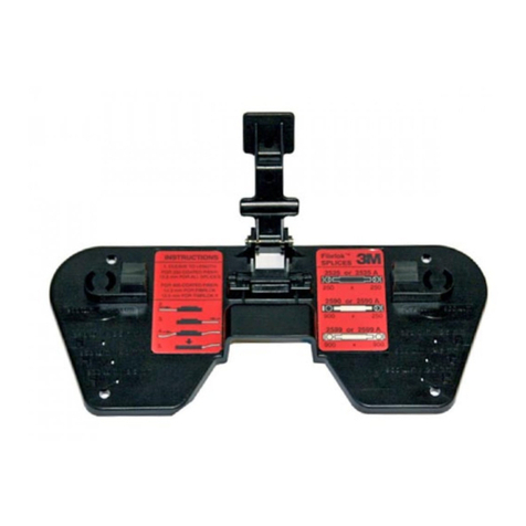
3443-112 Locator Plate
3442-44 Platen
3442-1A Platen
Instructions for the assembly of
8250 and 8350 D Sub Connectors.
Recycled paper
40% Pre-consumer waste paper
10% Post-consumer waste paper
Litho in USA.
© 3M 1997 34-7041-8747-4 JHA/AYN
Electronic Products Division
6801 River Place Blvd.
Austin, TX 78726-9000
http://www.mmm.com/epd
General
3M™Manual and Pneumatic Assembly Presses and
accessory assembly equipment are recommended for the
termination of D Sub Connectors. 3M assembly equipment
is offered to reduce set-up time, to provide easier and
faster assembly, and to reduce assembly error.
The 3443-112 Locator Plate and 3442-44 Platen were
designed to assemble the 8250 D Sub Connector. The
3443-112 Locator Plate is used with the 3442-1A Platen to
assemble the 8350 D Sub Connector.
*Included with the 3343-112 Locator Plate is a 3442-44 Platen.
The 3442-44 Platen can also be purchased separately.
Assembly Press Base
Mounting Holes
(4 places)
Platen to Locator Plate
Alignment Guides
End Guide
Assembly Pocket
3443-112 Locator Plate
3M cable types can be
assembled to either connector
with the 3443-112 Locator Plate.
Adjustment
Shaft Mount
Platen Clip
3442-44 Platen
(3442-1A not shown)
Connector
Part number
8250
8350
Locator
Plate Number
*3443-112
*3443-112
Platen
Part Number
3443-44
3443-1A
Assembly Presses
3640/3316
15
20
Assembly Presses
3335/3339-1
15 1/2
20 1/2
Assembly
Press
3830
3830
3436-1A Shut Height Setting
Figure 1: 3443-112 Locator Plate
Procedures for set-up:
Adjust the shut height setting (see Figures 2 through 4).
Important Notice
All statements, technical information, and recommendations related to
Seller’s products are based on information believed to be reliable, but the
accuracy or completeness thereof is not guaranteed. Before utilizing the
product, the user should determine the suitability of the product for its
intended use. The user assumes all risks and liability whatsoever in
connection with such use.
Any statements or recommendations of the Seller which are not contained
in the Seller’s current publications shall have no force or effect unless
contained in an agreement signed by an authorized officer of Seller. The
statements contained herein are made in lieu of all warranties, expressed
or implied, including but not limited to the implied warranties of
merchantability and fitness for a particular purpose which warranties are
hereby expressly disclaimed.
SELLER SHALL NOT BE LIABLE TO THE USER OR ANY OTHER PERSON
UNDER ANY LEGAL THEORY, INCLUDING BUT NOT LIMITED TO
NEGLIGENCE OR STRICT LIABILITY, FOR ANY INJURY OR FOR ANY
DIRECT OR CONSEQUENTIAL DAMAGES SUSTAINED OR INCURRED BY
REASON OF THE USE OF ANY OF THE SELLER’S PRODUCTS THAT
WERE DEFECTIVE.
Contact 3M Electronic Products Division Customer
Service for health, safety and environmental
information. Technical, sales and ordering
information can also be obtained through the
Customer Service Department.
Phone: 1-800-225-5373
Fax: 1-800-325-5329
To receive this technical document via fax on demand,
call the 3M Automated Information Response System
at 1-800-225-5375. Use tech sheet number TS 0764-01.
1
Procedures for
Connector/Cable Assembly
1. Grasp a D Sub cover strip between thumb and
forefinger of both hands, with the liner facing you.
Rotate the outermost cover down against the adjacent
cover on the strip, breaking it from the liner. Pull
laterally away from the strip. Adhesive should be
present on cover.
(See Figure 5)
2. Firmly press the ribbed side of the cable into alignment
grooves on cover. The adhesive will help the cable stay
in place. Visually inspect to ensure that:
a. Cable is properly aligned to cover grooves.
b. Cable end is flush with the cover for end
terminations or perpendicular to cover for midspan
terminations. (See Figure 6)
3. Place the cable/cover sub-assembly between the guides
on the locator plate, cover side down. (See Figure 7)
4. Position and orient connector body, contacts down,
over the cable/cover sub-assembly, aligning cover with
the body. (See Figure 7)
5. Lower the PRESS HANDLE firmly to complete the
Cable/Connector Assembly. (See Figure 8)
6. Raise press handle and remove completed assembly.
Visually inspect to ensure that:
a. Cover is fully seated and parallel with the body.
b. Cable is properly aligned with the cover grooves.
c. Cover retaining devices on the body are flush with
the cover end.
Procedures for
Adjusting Shut Height
Shut height settings are guidelines for proper termination
depth.
The shut height adjustment is made from the base of the
assembly press without the locator plate and platen in
place.
1. Place the shut height gauge, 3436-1A, across the press
base. (See Figures 2 and 3)
2. Lower the handle of the press until the handle casting
makes contact with the press casting. (See Figure 2)
3. Rotate the shut height adjustment feature until the
bottom of the shaft contacts the desired position on the
gauge.
4. Install the locator plate and the appropriate platen on
the press. The platen should be positioned parallel with
the connector body and cover.
NOTE: See the chart on page one for the appropriate shut
height setting.
Figure 2
Figure 2
Figure 3
Figure 3
Figure 4
Press Handle
Press Shaft
Shut Height Gauge
Locking Ring
Shut Height Adjustment
Collar
3335 Assembly Press
3640 Assembly Press
Shut Height Adjustment
Knob
CW (Lower)
CW (Raise)
2
Figure 4
Figure 5
3
Figure 4
Figure 6
4
Figure 4
Figure 7
Figure 8
2 3
Procedures for
Connector/Cable Assembly
1. Grasp a D Sub cover strip between thumb and
forefinger of both hands, with the liner facing you.
Rotate the outermost cover down against the adjacent
cover on the strip, breaking it from the liner. Pull
laterally away from the strip. Adhesive should be
present on cover.
(See Figure 5)
2. Firmly press the ribbed side of the cable into alignment
grooves on cover. The adhesive will help the cable stay
in place. Visually inspect to ensure that:
a. Cable is properly aligned to cover grooves.
b. Cable end is flush with the cover for end
terminations or perpendicular to cover for midspan
terminations. (See Figure 6)
3. Place the cable/cover sub-assembly between the guides
on the locator plate, cover side down. (See Figure 7)
4. Position and orient connector body, contacts down,
over the cable/cover sub-assembly, aligning cover with
the body. (See Figure 7)
5. Lower the PRESS HANDLE firmly to complete the
Cable/Connector Assembly. (See Figure 8)
6. Raise press handle and remove completed assembly.
Visually inspect to ensure that:
a. Cover is fully seated and parallel with the body.
b. Cable is properly aligned with the cover grooves.
c. Cover retaining devices on the body are flush with
the cover end.
Procedures for
Adjusting Shut Height
Shut height settings are guidelines for proper termination
depth.
The shut height adjustment is made from the base of the
assembly press without the locator plate and platen in
place.
1. Place the shut height gauge, 3436-1A, across the press
base. (See Figures 2 and 3)
2. Lower the handle of the press until the handle casting
makes contact with the press casting. (See Figure 2)
3. Rotate the shut height adjustment feature until the
bottom of the shaft contacts the desired position on the
gauge.
4. Install the locator plate and the appropriate platen on
the press. The platen should be positioned parallel with
the connector body and cover.
NOTE: See the chart on page one for the appropriate shut
height setting.
Figure 2
Figure 2
Figure 3
Figure 3
Figure 4
Press Handle
Press Shaft
Shut Height Gauge
Locking Ring
Shut Height Adjustment
Collar
3335 Assembly Press
3640 Assembly Press
Shut Height Adjustment
Knob
CW (Lower)
CW (Raise)
2
Figure 4
Figure 5
3
Figure 4
Figure 6
4
Figure 4
Figure 7
Figure 8
2 3
3443-112 Locator Plate
3442-44 Platen
3442-1A Platen
Instructions for the assembly of
8250 and 8350 D Sub Connectors.
Recycled paper
40% Pre-consumer waste paper
10% Post-consumer waste paper
Litho in USA.
© 3M 1997 34-7041-8747-4 JHA/AYN
Electronic Products Division
6801 River Place Blvd.
Austin, TX 78726-9000
http://www.mmm.com/epd
General
3M™Manual and Pneumatic Assembly Presses and
accessory assembly equipment are recommended for the
termination of D Sub Connectors. 3M assembly equipment
is offered to reduce set-up time, to provide easier and
faster assembly, and to reduce assembly error.
The 3443-112 Locator Plate and 3442-44 Platen were
designed to assemble the 8250 D Sub Connector. The
3443-112 Locator Plate is used with the 3442-1A Platen to
assemble the 8350 D Sub Connector.
*Included with the 3343-112 Locator Plate is a 3442-44 Platen.
The 3442-44 Platen can also be purchased separately.
Assembly Press Base
Mounting Holes
(4 places)
Platen to Locator Plate
Alignment Guides
End Guide
Assembly Pocket
3443-112 Locator Plate
3M cable types can be
assembled to either connector
with the 3443-112 Locator Plate.
Adjustment
Shaft Mount
Platen Clip
3442-44 Platen
(3442-1A not shown)
Connector
Part number
8250
8350
Locator
Plate Number
*3443-112
*3443-112
Platen
Part Number
3443-44
3443-1A
Assembly Presses
3640/3316
15
20
Assembly Presses
3335/3339-1
15 1/2
20 1/2
Assembly
Press
3830
3830
3436-1A Shut Height Setting
Figure 1: 3443-112 Locator Plate
Procedures for set-up:
Adjust the shut height setting (see Figures 2 through 4).
Important Notice
All statements, technical information, and recommendations related to
Seller’s products are based on information believed to be reliable, but the
accuracy or completeness thereof is not guaranteed. Before utilizing the
product, the user should determine the suitability of the product for its
intended use. The user assumes all risks and liability whatsoever in
connection with such use.
Any statements or recommendations of the Seller which are not contained
in the Seller’s current publications shall have no force or effect unless
contained in an agreement signed by an authorized officer of Seller. The
statements contained herein are made in lieu of all warranties, expressed
or implied, including but not limited to the implied warranties of
merchantability and fitness for a particular purpose which warranties are
hereby expressly disclaimed.
SELLER SHALL NOT BE LIABLE TO THE USER OR ANY OTHER PERSON
UNDER ANY LEGAL THEORY, INCLUDING BUT NOT LIMITED TO
NEGLIGENCE OR STRICT LIABILITY, FOR ANY INJURY OR FOR ANY
DIRECT OR CONSEQUENTIAL DAMAGES SUSTAINED OR INCURRED BY
REASON OF THE USE OF ANY OF THE SELLER’S PRODUCTS THAT
WERE DEFECTIVE.
Contact 3M Electronic Products Division Customer
Service for health, safety and environmental
information. Technical, sales and ordering
information can also be obtained through the
Customer Service Department.
Phone: 1-800-225-5373
Fax: 1-800-325-5329
To receive this technical document via fax on demand,
call the 3M Automated Information Response System
at 1-800-225-5375. Use tech sheet number TS 0764-01.
1

This manual suits for next models

4

Other 3M Industrial Equipment manuals

3M 3M-Matic 300cf Datasheet

3M

3M 3M-Matic 300cf Datasheet

3M Fibrlok II 2529 User manual

3M

3M Fibrlok II 2529 User manual

3M Crimplok 8702-UPC User manual

3M

3M Crimplok 8702-UPC User manual

3M 3M-Matic 800rf Datasheet

3M

3M 3M-Matic 800rf Datasheet

3M Liqui-Cel EXF-10x28 Series Installation instructions

3M

3M Liqui-Cel EXF-10x28 Series Installation instructions

3M 4300 Series User manual

3M

3M 4300 Series User manual

3M Flexiguard 8560025 Operator's manual

3M

3M Flexiguard 8560025 Operator's manual

3M FDC 08M User manual

3M

3M FDC 08M User manual

3M 3MAPPM150 User manual

3M

3M 3MAPPM150 User manual

3M 4220CUE-6000 User manual

3M

3M 4220CUE-6000 User manual

3M 39600 Datasheet

3M

3M 39600 Datasheet

3M 50AN Specification sheet

3M

3M 50AN Specification sheet

3M QT-III User manual

3M

3M QT-III User manual

3M Dynatel 2250M User manual

3M

3M Dynatel 2250M User manual

3M Scotchlok Tap Connector 558 User manual

3M

3M Scotchlok Tap Connector 558 User manual

3M Wrist Strap and Ground Monitor 773 User manual

3M

3M Wrist Strap and Ground Monitor 773 User manual

3M MEMBRANA Liqui-Cel Instruction Manual

3M

3M MEMBRANA Liqui-Cel Instruction Manual

3M Flexiguard 8517762 Operator's manual

3M

3M Flexiguard 8517762 Operator's manual

3M Liqui-Cel EXF-14 28 Series Installation instructions

3M

3M Liqui-Cel EXF-14 28 Series Installation instructions

3M 3M-Matic Accuglide NPH 11200 Datasheet

3M

3M 3M-Matic Accuglide NPH 11200 Datasheet

3M 4084 User manual

3M

3M 4084 User manual

3M UniPresser 3M710 User manual

3M

3M UniPresser 3M710 User manual

3M 3M-Matic 8000af Datasheet

3M

3M 3M-Matic 8000af Datasheet

3M Fibrlok II User manual

3M

3M Fibrlok II User manual

Popular Industrial Equipment manuals by other brands

JYTEK Thunderbolt PXIe-62314T manual

JYTEK

JYTEK Thunderbolt PXIe-62314T manual

Eriez HS36 Installation, operation and maintenance instructions

Eriez

Eriez HS36 Installation, operation and maintenance instructions

ABB HT606747 manual

ABB

ABB HT606747 manual

Dr.X Works G1-ISOK product manual

Dr.X Works

Dr.X Works G1-ISOK product manual

ABB HT570026 Operation manual

ABB

ABB HT570026 Operation manual

Hix HOBBY LITE owner's manual

Hix

Hix HOBBY LITE owner's manual

Panasonic EXB 14AT Series manual

Panasonic

Panasonic EXB 14AT Series manual

Eaton PKE12 Series Instruction leaflet

Eaton

Eaton PKE12 Series Instruction leaflet

TopGears ITG 125 manual

TopGears

TopGears ITG 125 manual

ABB ACS880-37LC-0390A-7 Hardware manual

ABB

ABB ACS880-37LC-0390A-7 Hardware manual

Meritor MM-0164 Maintenance manual

Meritor

Meritor MM-0164 Maintenance manual

Electrothermal MH8517 Instruction book

Electrothermal

Electrothermal MH8517 Instruction book

John Crane 5610VQ Installation, operation & maintenance instructions

John Crane

John Crane 5610VQ Installation, operation & maintenance instructions

Maxcess FIFE-500-XL Installation and service manual

Maxcess

Maxcess FIFE-500-XL Installation and service manual

ABB HT562900 Operation manual

ABB

ABB HT562900 Operation manual

ABB HT595275 Operation manual

ABB

ABB HT595275 Operation manual

Dodge Torque-Arm II instruction manual

Dodge

Dodge Torque-Arm II instruction manual

ABB HT576624 Operation manual

ABB

ABB HT576624 Operation manual

manuals.online logo
manuals.online logoBrands
  • About & Mission
  • Contact us
  • Privacy Policy
  • Terms and Conditions

Copyright 2025 Manuals.Online. All Rights Reserved.