ZWAE MARK40 Manual

Installation and Service Manual
Zakład Wytwórczy Aparatów Elektrycznych Sp. z o.o.
MARK40
Vertical disconnector 123, 245 i 420 kV
Manual No. DTR.01.04.04.EN

Zakład Wytwórczy Aparatów Elektrycznych Sp. z o.o.
2
zwae.com.pl
WARNING!
During the operation of electrical equipment, certain parts of
these devices are normally under dangerous voltage, and me-
chanical parts, also remotely controlled, can move quickly.
Failure to follow the warning instructions can result in serious
personal injuries or material damage.
Only suitably qualied personnel can work on or near the device.
This personnel must know exactly all safety rules and rules for
maintaining the device in accordance with this instruction.
The problem-free and safe operation of this device requires
proper transport, proper storage, construction and assembly as
well as careful service and maintenance.

Zakład Wytwórczy Aparatów Elektrycznych Sp. z o.o.
3
Table of contents
1. TRANSPORT ...................................... 5
1.1. Unpacking and inspection ........................... 5
1.2. Storage and transport............................... 5
2. DESCRIPTION ...................................... 7
2.1. Construction and principle of operation ................ 7
2.2. Climatic conditions. . . . . . . . . . . . . . . . . . . . . . . . . . . . . . . . . 9
2.3. Nameplate ........................................ 9
2.4. Basic technical parameters .......................... 10
3. INSTALLATION AND ADJUSTMENT .................... 11
3.1. Preparation of contact surfaces ...................... 11
3.2. Assembling of the base frame........................ 12
3.3. Assembling of the insulators ......................... 13
3.4. Assembling of the movable contact head .............. 16
3.5. Assembling of the xed contact head with current path .. 16
3.6. Assembling of the corona ring of the knife ............. 17
3.7. Assembling of the corona rings of the movable
contact head of the knife ................................ 18
3.8. Assembling of the corona rings of the xed contact head. 18

Zakład Wytwórczy Aparatów Elektrycznych Sp. z o.o.
4
3.9. Assembling of the operating mechanism............... 19
3.10. Assembling of the driving shaft. . . . . . . . . . . . . . . . . . . . . . 19
3.11. Assembling of the xed contact of the earthing switch.. 20
3.12. Assembling and adjustment of the knife of the
earthing switch......................................... 21
3.13. Assembling of the earthing cable .................... 24
3.14. Table of tightening torque for screws [Nm] ............ 25
4. OPERATING MANUAL ............................... 25
4.1. Notes on switching operations....................... 25
5. INSPECTIONS AND MAINTENANCE .................... 26
5.1. Visual inspections ................................. 26
5.2. Periodic inspections................................ 26
5.3.Spare parts and recommended maintenance materials ... 26
6. UTILIZATION ....................................... 27

Zakład Wytwórczy Aparatów Elektrycznych Sp. z o.o.
5
1. TRANSPORT
1.1. Unpacking and inspection
Immediately after receiving the disconnector, the delivery’s compliance with the packing list should be chec-
ked. Then one should check whether the disconnector has not been mechanically damaged during transport
and the data on the nameplate match the order.
1.2. Storage and transport
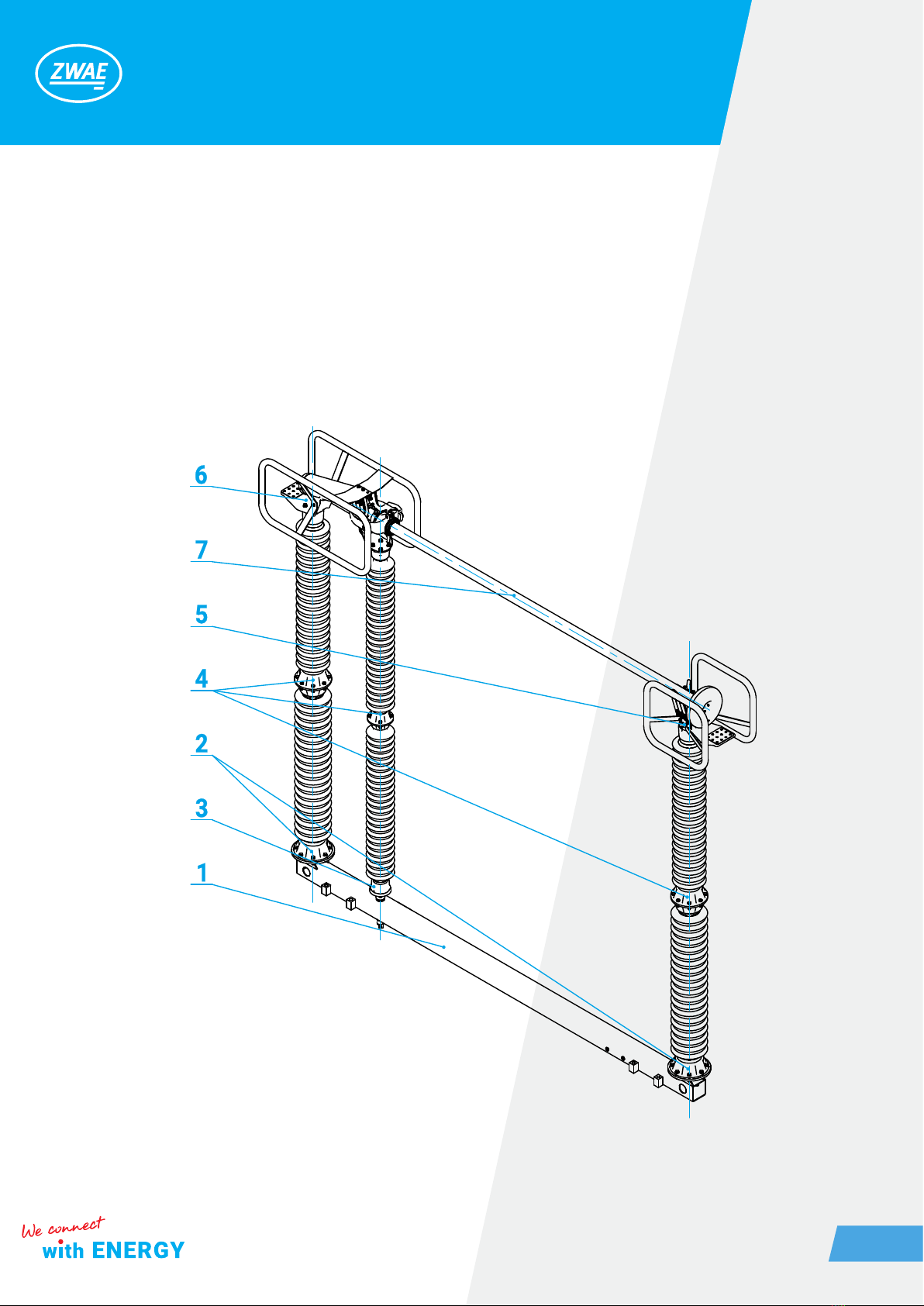
The disconnectors poles are transported in a partially assembled condition, ie the base frame together with
the current path form the basic set, while the other elements (insulators, contact’s corona rings, driving soc-
kets, etc.) are delivered separately for installing during assembly. The basic sets are packed in several pieces
on a wooden structure, as it is shown in the following drawing.
wooden structure
In the case of the purchase of a disconnector’s version with an earthing switch, all parts used for the earthing
switch’s construction ( the knife of earthing switch, counterweight beams, counterweights, pins, spacers, co-
upling tie rods, earthing switch contact, knife’s support and shaft of the earthing switch) are also delivered se-
parately in packs. When preparing the pole for assembly, the wooden beams should be removed by unscrewing
the four screws with the spanner 13.

Zakład Wytwórczy Aparatów Elektrycznych Sp. z o.o.
6
During unloading, the disconnector’s poles should be lifted with a forklift, as shown in the following graphics.
8x140 (4 pcs)

Zakład Wytwórczy Aparatów Elektrycznych Sp. z o.o.
7
During transportation, the poles must be secured against tipping over and the disconnector knife should be
closed. Disconnector can be transported by means of transport with open cargo area. Disconnectors poles
can be stored in an open space, but poles should be set so that the base frame does not stand directly on the
ground.
2. DESCRIPTION
2.1. Construction and principle of operation
The outdoor disconnector type Mark-40 is a three-column insulating switch with the secant movement of
contacts in the vertical plane, intended for work in networks with voltage depending on the version (123-420
kV) at frequencies up to and including 50 Hz. The disconnector can be used as a single-pole switch with an
individual operating mechanism. Disconnector’s poles can be set in parallel or in series. A visual sketch of
the Mark-40 disconnector pole with two earthing switches is presented below.
current path
supporting insulator
earthing switch (UN)
driving insulator
base frame
earthing switch (UR)
supporting structure
disconnector’s operating mechanism
earthing switch’s operating mechanism

Zakład Wytwórczy Aparatów Elektrycznych Sp. z o.o.
8
Details of the Mark-40 disconnector’s pole construction are illustrated in the next drawing. Each pole possess
an individual base frame [1] equipped with two xed feet [2] and a rotating foot [3] on which porcelain insulators
[4] are mounted. On top of the insulators are assembled the followings: movable contact head [5], xed contact
head [6] used to transfer the rotating movement of the driving insulator to the secant movement of current
path [7].

Zakład Wytwórczy Aparatów Elektrycznych Sp. z o.o.
9
2.2. Climatic conditions
The disconnector is adapted for outdoor operation, at ambient temperature from -40 to +40 ° C and relative
humidity up to 100%.
2.3. Nameplate
DISCONNECTING SWITCH
Rated voltage
weight
rated short-circuit withstand current (1sec.)
Lightning impulse withstand voltage
rated continuous current

Zakład Wytwórczy Aparatów Elektrycznych Sp. z o.o.
10
2.4. Basic technical parameters
No Parameter Value
1. Rated operating voltage 123 [kV] 245 [kV] 420 [kV]
2. Rated continuous current
2500 [A]
3150 [A]
4000 [A]
2500 [A]
3150 [A]
4000 [A
2500 [A]
3150 [A]
4000 [A]
3. Peak current 125 [kA] 125 [kA] 125 [kA]
4. Short-circuit current, 1 sec. 50 [kA] 50 [kA] 50 [kA]
5.
Test voltage (50 Hz):
- earth and pole to pole insulation
- contact to contact insulation
230 [kV]
265 [kV]
460 [kV]
530 [kV]
520 [kV]
610 [kV]
6.
Surge test voltage:
- earth and pole to pole insulation
- contact to contact insulation
550 [kV]
630 [kV]
1050 [kV]
1200 [kV]
1425 [kV]
1425 (+240)* [kV]
7.
Operational rated surge test voltage:
- earth insulation
- contact to contact insulation
-
-
-
-
1050 [kV]
900 (+345)* [kV]
8. Radio interference voltage <2500 [µV] <2500 [µV] <2500 [µV]
9. Mechanical strength 2000 cycles 2000 cycles 2000 cycles
10. Motor operating mechanism NSO80 NSO80 NSO80
* Peak values of alternating voltage supplied to the opposite terminal are shown in brackets

Zakład Wytwórczy Aparatów Elektrycznych Sp. z o.o.
11
3. INSTALLATION AND ADJUSTMENT
The disconnector is delivered partially assembled, as shown in the following gure.
The assembly is limited to:
a) assembling and leveling the base frame on the supporting structure,
b) assembling and setting of insulators,
c) assembling of movable contact head and xed contact head,
d) assembling of corona rings,
e) assembling and coupling of the operating mechanism with disconnector,
f) earthing of the base frames and the operating mechanism.
3.1. Preparation of contact surfaces
The contact resistance of the connected elements depends primarily on the quality and cleanliness of the
contacting surfaces. Therefore, these surfaces should be prepared very precisely. The method of preparing of
aluminum, silver-plated and galvanized contact surfaces is shown below:
• aluminum – aluminium connection
The oxide layer should be removed from the contact surface by using a wire brush. After this treatment, the
surface should be matt gray, devoid of shiny areas. Any chips and aluminum dust should be thoroughly remo-
ved from the surface, eg by lubricating with acid-free petroleum jelly and then removing it. After this treatment,
the surface should be lubricated with acid-free petroleum jelly to protect it from oxidation of aluminum. Such
prepared surface should not be exposed to the interaction of the atmosphere longer than the time needed to
prepare the cooperating surface.

Zakład Wytwórczy Aparatów Elektrycznych Sp. z o.o.
12
• copper – silver connection
The copper surfaces should be cleaned of oxides by using a brass wire brush and then should be proceeded
as for the aluminum surface. Silver-plated surfaces do not need to be cleaned with a brush, but they can be
cleaned with a delicate abrasive material, eg steel wool. After cleaning the surface should be covered with a
thin layer of acid-free petroleum jelly.
• zinc – zinc connection
The surfaces should be cleaned by using of steel wire brush and then covered with a thin layer of grease.
3.2. Assembling of the base frame
Used elements:
1. Base frame of the disconnector – 1pc.
2. - screw M20x140 – 8 pcs.
- Spring washer 20 – 8 pcs.
- Nut M20 – 8 pcs.
After mounting the base frame, one should
check the level of the surface in two planes.

Zakład Wytwórczy Aparatów Elektrycznych Sp. z o.o.
13
3.3. Assembling of the insulators
Insulators are recommended to be screwed when they are on the ground and then mounted on the
disconnector’s base frame using a crane.
Used elements:
1. supporting insulator - 2 pcs.
2. supporting insulator - 2 pcs.
3. driving insulator - 1 pc.
4. - screw M16x65 - 16 pcs.
- spring washer 16 - 16 pcs.
- nut M16 - 16 pcs.
5. - screw M16x60 - 16 pcs.
- washer 17 - 32 pcs.
- spring washer 16 - 16 pcs.
- nut M16 - 16 pcs.
6. - screw M16x40 - 4 pcs.
- washer 17 - 4 pcs.
- spring washer 16 - 4 pcs.
7. - screw M16x50 - 4 pcs.
- spring washer 16 - 4 pcs.
- nut M16 - 4 pcs.
The insulators assembled on the base frame should be set in one plane. For that purpose is recommended usage
of cord, which provided from hole [1] axis to hole [2] axis enables insulators to be set in one plane [3].

Zakład Wytwórczy Aparatów Elektrycznych Sp. z o.o.
14
The adjustment is made with the use of adjustment washers allowing for proper adjustment of deviation of insu-
lators. This method is presented on the next two drawings.
After setting the plane of insulators, one should set the distance of the driving insulator.

Zakład Wytwórczy Aparatów Elektrycznych Sp. z o.o.
15
This adjustment is made using the tool shown in the following drawings. The tool should be mounted on the xed
insulator [2]. By rotating the driving insulator [1], one should determine potential deviations from the axis indica-
ted by the tool. If necessary, the adjustments should be made in the manner discussed earlier. The permissible
radial runout of the center of the driving insulator is 1 mm.

Zakład Wytwórczy Aparatów Elektrycznych Sp. z o.o.
16
3.4. Assembling of the movable contact head
After the insulators are properly adjusted, the mova-
ble contact head is mounted [1].
Used elements:
- screw M16x40 - 4 pcs.
- washer 17 - 4 pcs.
- spring washer 16 - 4 pcs.
3.5. Assembling of the xed contact head with cu-
rrent path
The xed contact head is assembled using a crane.
The way of hanging the xed contact head with the
current path is shown in the drawing.

Zakład Wytwórczy Aparatów Elektrycznych Sp. z o.o.
17
Used elements:
2. - screw M16x40 - 8 pcs.
- washer 17 - 8 pcs.
- spring washer 16 - 8 pcs.
Used elements:
1. - screw M6x20 - 4 pcs.
- washer 6,4 - 4 pcs.
- spring washer 6,4 - 4 pcs.
3.6. Assembling of the corona ring of the knife

Zakład Wytwórczy Aparatów Elektrycznych Sp. z o.o.
18
3.7. Assembling of the corona rings of the movable contact head of the knife
3.8. Assembling of the corona rings of the xed contact head
Used elements:
1. - screw M12x25 - 2 pcs.
- washer 13 - 2 pcs.
- spring washer 12 - 2 pcs.
2. - screw M12x25 - 2 pcs.
- washer 13 - 2 pcs.
- spring washer 12 - 2 pcs.
Used elements:
1. - screw M12x25 - 4 pcs.
- washer 13 - 4 pcs.
- spring washer 12 - 4 pcs.

Zakład Wytwórczy Aparatów Elektrycznych Sp. z o.o.
19
3.9. Assembling of the operating mechanism
3.10. Assembling of the driving shaft
Used elements: 1. - screw M16x45 - 2 pcs.
- washer 17 - 2 pcs.
- spring washer 17- 2 pcs.
Used elements:
1. driving socket - 1 pc.
2. - screw M12x30 - 1 pc.
- spring washer 12 - 1 pc.
3. - pin 80mm - 1 pc.
4. - screw M12x120 - 4 pcs.
- washer 13 - 8 pcs.
- spring washer 12 - 4 pcs.
- nut M12 - 4 pcs.

Zakład Wytwórczy Aparatów Elektrycznych Sp. z o.o.
20
3.11. Assembling of the xed contact of the earthing switch
The earthing switch type UN-4 is assembled to the disconnector type Mark-40. The assembly of it is taking pla-
ce during the assembly of the disconnector. Components and the method of assembling of the xed contact
of the earthing switch is presented in the next drawing.
Used elements (the given quantities refer to a single ear-
thing switch):
1. xed contact of the earthing switch – 1 pc.
2. corona ring of the earthing switch – 1 pc.
3. spacer – 1 pc. *
4. - screw M10x25 – 2 pcs.
- washer 10 – 4 pcs.
- spring washer 10 – 2 pcs.
- nut M10 – 2 pcs.
5. - nut M16 – 4 pcs. (UN only)
- washer 17 – 4 pcs.
- spring washer 16 – 4 pcs.
6. Pin M16x95 – 4 pcs.
* If only the UN earthing switch is assembled, the spacer
washer is also assembled under the movable contact
head of the disconnector. If only the UR earthing switch
is assembled, the spacer washer is assembled on the
driving insulator and supporting insulator of the xed
contact head of current path.
Table of contents
Other ZWAE Industrial Equipment manuals