Delta CTA4000A Series User manual

1
2013/3/13
Timer / Counter / Tachometer Instruction Sheet
Thank you very much for purchasing DELTA CTA series. Please read this instruction sheet before using your CTA series
to ensure proper 3operation and please keep this instruction sheet handy for quick reference.
DANGER! Caution! Electric Shock! When the power is on, DO NOT touch the AC terminals in case an
electric shock may occur. Make sure the power is disconnected when you check the unit inside.
CTA series is an OPEN-TYPE device. They are intended for installation completely within an overall panel
and are for use in counting or timing application. If it will cause serious injury to workers or damage on other
equipments when used in a dangerous environment, please make sure it is installed in an automatic safety
protection device.
Precaution
1. Always use recommended solder-less terminals: Fork terminal with isolation (M3 screw, width 7.0mm), hole (diameter
3.2mm). Screw size: M3x6.5 (with 6.8x6.8 square washer). Recommended tightening torque: 0.4 N.m (4kgf.cm).
Applicable wire: solid/twisted wire of 2mm2, 12AWG to 24 AWG. Please be sure to tighten them properly.
2. Prevent dust or metallic debris from falling into the device and cause malfunctions.
3. DO NOT modify or uninstall the device.
4. DO NOT use empty terminals.
5. Make sure the wires are correctly connected to proper terminals.
6. Keep away from high-voltage and high-frequency environment during installation in case of interference.
7. Prevent using the device in premises which contain:
․Dust or corrosive gas ․High humidity ․High radiation ․Vibration and shock
8. CTA series is an open-type device. Make sure to install it in an enclosure to prevent dust, humidity in case of an
electric shock.
9. Please make sure the power cables and signal device are installed correctly before switching on the power; otherwise
serious damage may occur.
10. DO NOT touch the terminals or repair the device when the power is on; otherwise an electric shock may occur.
11. Please wait for one minute after the power is switched off to allow the capacitor to discharge and DO NOT touch the
internal wiring within this period.
12. Use dry cloth to clean the device. DO NOT use acid or alkaline liquid to clean the device.
Display, Indicators and Keys
LCD Display & Indicators
RST 1/2 Light on when reset signal is detected BATCH “Batch Counting Mode” in Counter and Tachometer
function
K/P 1/2 Light on when key-protected mode is
enabled SET 1 2 SV1, SV2 display
OUT 1/2 Light on when output is executing TAC Light on when Tachometer function is executing
H M S Hour, minute, second, unit of timer,
displayed in Timer function CNT Light on when Counter function is executing
VARITEL INGENIERIA ELECTRONICA S.A.
Manuel Baliña 456, Lomas de Zamora (B1832CCJ) Buenos Aires, Argentina.

2
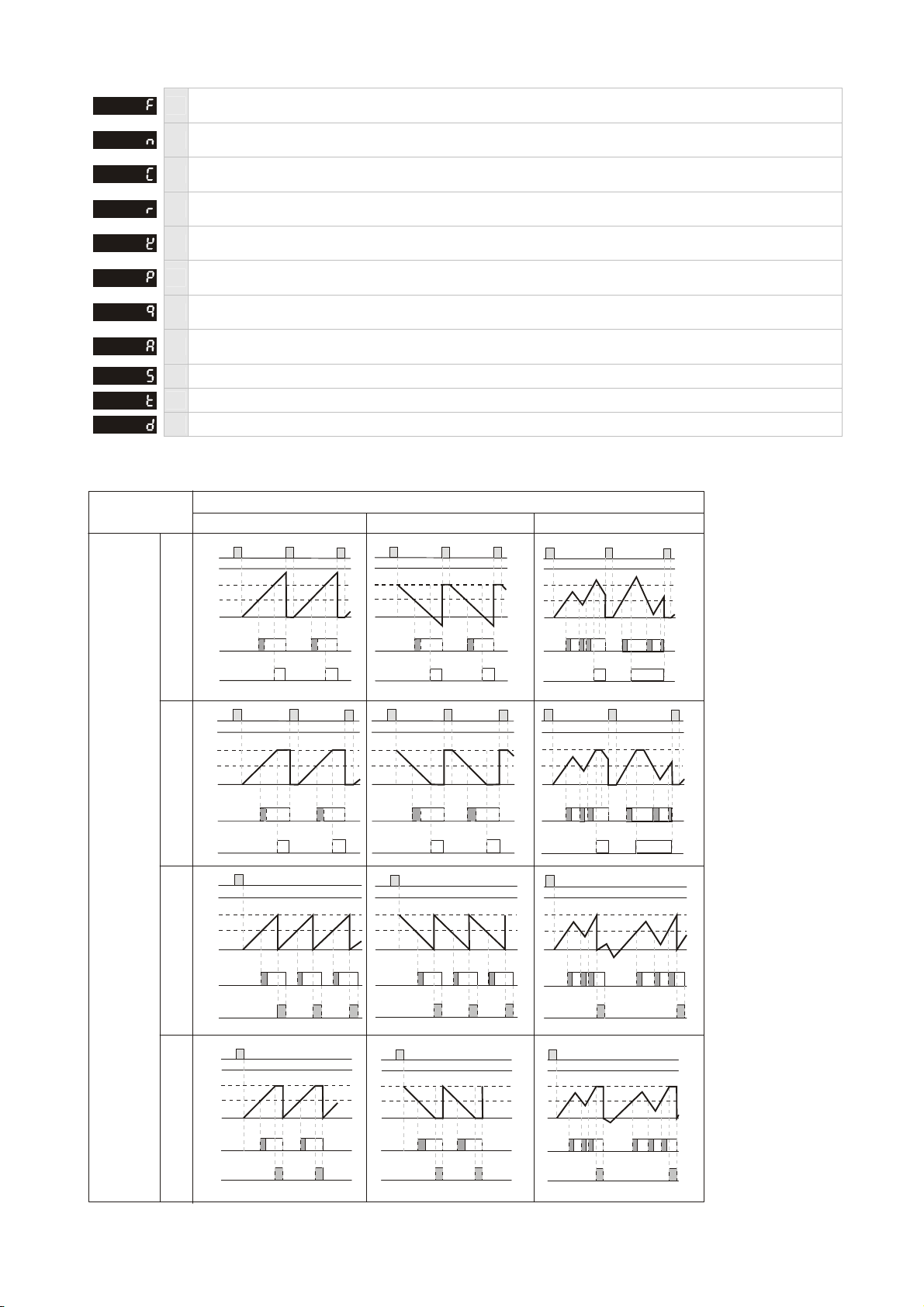
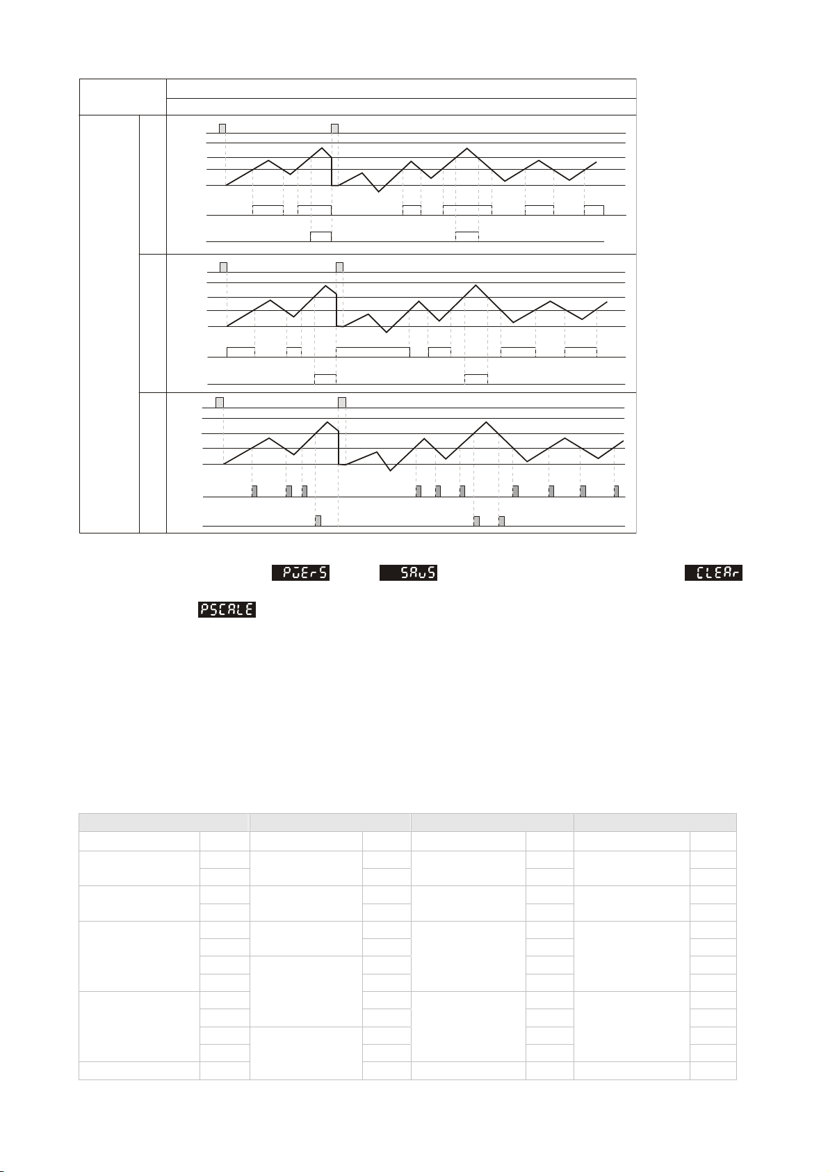
TOTAL “Total Counting Mode” in Counter and
Tachometer function TMR Light on when Timer function is executing
Key Operation
Increase and decrease SV or change parameter settings.
Left move 1 digit of the selected digit. The indicator of the selected digit will flash.
MODE
Save the set parameters or switch among functions.
LOCK
Prevent settings from being changed. Key-protected mode still works after the power is switched off. Press
LOCK to enter key-protected mode. In non-key-protected status, press LOCK to enter Lock 1. In Lock 1,
press LOCK again to enter Lock 2. Press
MODE
and at the same time to disable key-protected mode.
(Lock 1) disables the functions of all keys. (Lock 2) allows users to change SV and
functions of RESET remain. LOCK only functions in non-key-protected status.
RESET Clear and reset PV.
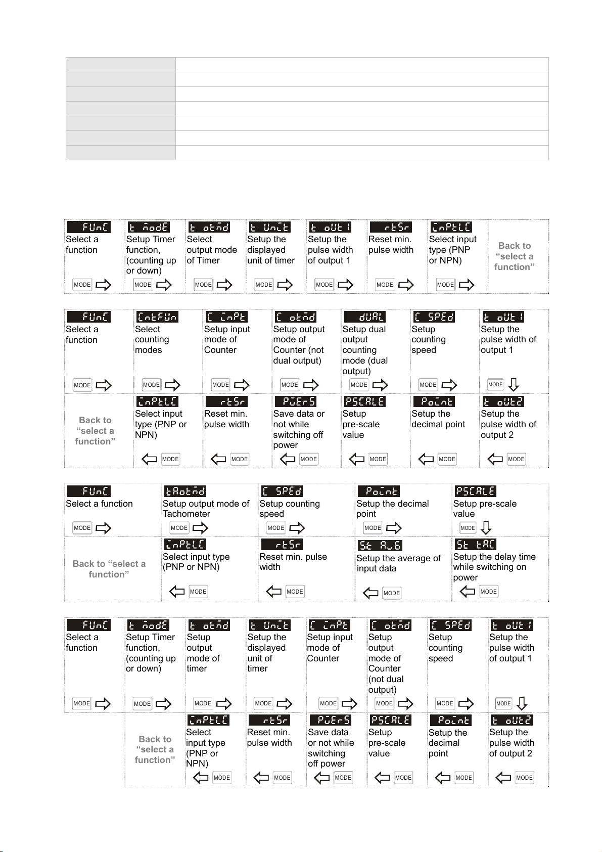
Modes: Operation Mode and Configuration Mode
Operation
When the power is on, the timer/counter/tachometer is in the operation mode. Press to
change SV, or to make change on a desired digit. The indicator of the selected digit will flash.
After the change is made, press
MODE
to save the setting. If SV or parameters are not changed, press
MODE
once to switch between SET1 and SET2.
Configuration Press
MODE
in operation mode for more than 3 seconds to enter configuration mode. Press
MODE
once to switch among parameters. To return to operation mode, press
MODE
for more than 3 seconds.
Ordering Information
CTA
2
345
61
nProduct name CTA: Delta Counter/Timer/Tachometer A series qPreset stage 0: 2 preset stage
oPanel size 4: 48mm x 48mm 1/16DIN rCommunication 0: none; 1: RS-485
pOutput 2 0: NPN; 1: Relay sPower supply A: AC 100 ~ 240V;
D: DC 21.6 ~ 26.4V
Specification
Model name CTA4000A series CTA4000D series
Power input AC 100 ~ 240V, 50/60Hz DC 24V
Input voltage range 85 ~ 110%, rated voltage DC 21.6 ~26.4V
Power consumption Less than 10VA Less than 5W
External power supply 12V DC ±10%, 100mA
Display Double-line, 6-digit negative transmissive LCD display
Non-voltage input (NPN): ON impedance 1K ohm max. ON residual voltage: 2V max.
Input signal Voltage input (PNP): High level: 4.5 to 30V DC, Low level: 0 to 2V DC
Relay: SPST max.250V AC, 5A (resistance load)
Output 1 Transistor: NPN open collector. When 100mA /30V DC, residual voltage=1.5V DC max.
Relay: SPDT max.250V AC, 5A (resistance load)
Output 2 Transistor: NPN open collector. When 100mA /30V DC, residual voltage=1.5V DC max.
Dielectric strength 2,000V AC, 50/60 Hz for 1 minute 1,000V AC, 50/60Hz for 1 minute
VARITEL INGENIERIA ELECTRONICA S.A.
Manuel Baliña 456, Lomas de Zamora (B1832CCJ) Buenos Aires, Argentina.

3
Vibration resistance Without damage: 10 ~ 55Hz, amplitude=0.75mm, 3 axes for 2 hours
Shock resistance Without damage: drop 4 times, 300m/s2, 3 edges, 6 surfaces and 1 corner
Ambient temperature 0 ~ 50oC
Storage temperature -20 ~ +65oC
Altitude 2,000m or less
Ambient humidity 35 ~ 85% RH (non-condensing)
Pollution degree Degree 2
Parameters in Configuration Mode
Timer
Select a
function
MODE
Setup Timer
function,
(counting up
or down)
MODE
Select
output mode
of Timer
MODE
Setup the
displayed
unit of timer
MODE
Setup the
pulse width
of output 1
MODE
Reset min.
pulse width
MODE
Select input
type (PNP
or NPN)
MODE
Back to
“select a
function”
Counter
Select a
function
MODE
Select
counting
modes
MODE
Setup input
mode of
Counter
MODE
Setup output
mode of
Counter (not
dual output)
MODE
Setup dual
output
counting
mode (dual
output)
MODE
Setup
counting
speed
MODE
Setup the
pulse width of
output 1
MODE
Back to
“select a
function”
Select input
type (PNP or
NPN)
MODE
Reset min.
pulse width
MODE
Save data or
not while
switching off
power
MODE
Setup
pre-scale
value
MODE
Setup the
decimal point
MODE
Setup the
pulse width of
output 2
MODE
Tachometer
Select a function
MODE
Setup output mode of
Tachometer
MODE
Setup counting
speed
MODE
Setup the decimal
point
MODE
Setup pre-scale
value
MODE
Back to “select a
function”
Select input type
(PNP or NPN)
MODE
Reset min. pulse
width
MODE
Setup the average of
input data
MODE
Setup the delay time
while switching on
power
MODE
Timer + Counter
Select a
function
MODE
Setup Timer
function,
(counting up
or down)
MODE
Setup
output
mode of
timer
MODE
Setup the
displayed
unit of
timer
MODE
Setup input
mode of
Counter
MODE
Setup
output
mode of
Counter
(not dual
output)
MODE
Setup
counting
speed
MODE
Setup the
pulse width
of output 1
MODE
Back to
“select a
function”
Select
input type
(PNP or
NPN)
MODE
Reset min.
pulse width
MODE
Save data
or not while
switching
off power
MODE
Setup
pre-scale
value
MODE
Setup the
decimal
point
MODE
Setup the
pulse width
of output 2
MODE
VARITEL INGENIERIA ELECTRONICA S.A.
Manuel Baliña 456, Lomas de Zamora (B1832CCJ) Buenos Aires, Argentina.

4
Communication
Enable/
Disable
write
function
MODE
ASCII
/RTU
format
selection
MODE
Address
setting
MODE
Baud rate
setting
MODE
Date length
setting
MODE
Parity bit
setting
MODE
Stop bit
setting
MODE
Back to
“select a
function”
Open Communication parameter method:
1) Press “LOCK” key first, CTA will be in the lock status.
2) Press at the same time over 2 seconds, CTA will go to the special mode. Display【PASS】and【CtAxx0】.
3) When PV display【PASS】, Press keys, adjusting value to【4323】and press
MODE
key to confirm.
4) Restart the power on, we can see the communication setting parameters in the “setting mode”.
5) If CTA in lock status, we can press
MODE
and Keys as the same time to release lock status.
Timer Function
There are counting up/down modes, several counting units and output modes to choose from in timer function.
: Select counting up or counting down
: Setup the output time of timer, from 0 to 99.99 secs. 0= Hold output
: Setup output modes
: Setup the counting unit of the timer.
sec 0.01 ~ 9,999.99 A unit = 10ms. Max. counting = 9,999.99 secs.
sec 0.1 ~ 99,999.9 A unit = 0.1sec. Max. counting = 99,999.9 secs.
sec 1 ~ 999,999 A unit = 1 sec. Max. counting = 999,999 secs.
min, sec 0.01 ~ 9,959.99 A unit = 0.01 sec. Max. counting = 5,999.99 secs.
min, sec 0.1 ~ 99,959.9 A unit = 0.1 sec. Max. counting = 59,999.9 secs.
min 0.1 ~ 99,999.9 A unit = 0.1 min. Max. counting = 99,999.9 mins.
min 1 ~ 999,999 A unit = 1 min. Max. counting = 999,999 mins.
hr, min, sec 1 ~ 995,959 A unit = 1 sec. Max. counting = 359,999 secs (100hr)
hr, min 1 ~ 999,959 A unit = 1 min. Max. counting = 35,999,999 secs
(10,000hr)
hr 1 ~ 999,999 A unit = 1 hr. Max. counting = 999,999 hrs
P
ower s
i
gna
l
Start signal
Pause signal
Clear signal
Up
Down
0
0
SV
SV
Signal On Delay 1
tt
Output signal
Power signal
Start signal
Pause signal
Clear signal
Output signal
Up
Down
0
0
SV
SV
Signal On Delay 2
tt
VARITEL INGENIERIA ELECTRONICA S.A.
Manuel Baliña 456, Lomas de Zamora (B1832CCJ) Buenos Aires, Argentina.

5
Power signal
Start signal
Pause signal
Clear signal
Output signal
SV
0
Up
Down
SV
0
Signal Off Delay
Power signal
Start signal
Pause signal
Clear signal
Output signal
SV
0
Up
Down
SV
0
Si
g
nal On
Power signal
Start signal
Pause signal
Clear signal
Output signal
Up
Down
SV
SV
0
0
Power On Delay
ttt
Power signal
Start signal
Pause signal
Clear signal
Output signal
Up
Down
SV
SV
0
0
Power On Dela
y
Hold
tt t t
Power signal
Start signal
Pause signal
Clear signal
Output signal
Up
Down
SV
SV
Repeat C
y
cle
0
0
timer output set as 0
Power signal
Start signal
Pause signal
Clear signal
Output signal
Up
Down
SV
SV
Repeat Cycle
tt t
timer output not set as 0
Power signal
Start signal
Pause signal
Clear signal
Output signal
Up
Down
SV
SV
0
0
Repeat Cycle Hold
Timer out
p
ut set as 0
Power signal
Start signal
Pause signal
Clear signal
Output signal
Up
Down
SV
SV
0
0
RCYH timer output not set as 0
tt t
VARITEL INGENIERIA ELECTRONICA S.A.
Manuel Baliña 456, Lomas de Zamora (B1832CCJ) Buenos Aires, Argentina.

6
Input modes of counter
Counting up
Counting down
Command
Individual
Quadrature
Power signal
Start signal
Pause signal
Clear signal
Output signal
Up
Down
SV1
SV1
SV2
SV2
0
0
Repeat Cycle 2
Power signal
Start signal
Pause signal
Clear signal
Output signal
Up
Down
0
SV
SV
0
Signal Cumulate
Power signal
Start signal
Pause signal
Clear signal
Output signal
Up
Down
SV1
SV2
SV1
0
0
SV2
Signal Twin ON-Start
Power signal
Start signal
Pause signal
Clear signal
Output signal
Up
Down
SV1
SV1
SV2
SV2
0
0
Signal Twin OFF-Start
Counter Function
Counter functions include 1-stage counting, 2-stage counting, batch counting, total counting and dual counting.
1-stage Only 1 SV is allowed. See “output modes of counter”.
2-stage 2 SVs, 2 PVs are allowed. See “output modes of counter”.
Batch Apart from the counting of PV and SV, when PV=SV, the batch counting adds 1 and clear PV as 0
for recounting till the batch counting equals batch SV.
Total Total counting adds up all the counting values till they reach SV for output.
Dual CP1 and CP2 can be independent counters, but the counting speed can only reach 5kHz. CP1
and CP2 can execute addition or subtraction .
VARITEL INGENIERIA ELECTRONICA S.A.
Manuel Baliña 456, Lomas de Zamora (B1832CCJ) Buenos Aires, Argentina.

7
Counting up
Counting down
Prohibit
AA
0
1
2
3
4
H
L
H
L
0
CP1
CP2
Present
Value
CP1: Counter input CP2: Counter input prohibited
Note: has to be larger than width of min. Input signal
A
Prohibit
AA
0
1
2
3
4
5
H
L
H
L
0
CP1
CP2
Present
Value
CP1: Counter input prohibited CP2: Counter input
Note: has to be larger than width of min. Input signal
A
Prohibit
A
A
n
n-2
n-1
n-4
n-3
H
L
CP1
CP2
Present
Value
0
H
L
CP1: Counter input CP2: Counter input prohibited
Note: has to be larger than width of min. Input signal
A
A
Prohibit
A
n
n-1
n-2 n-3
n-4
n-5
H
L
H
L
CP1
CP2
0
Present
Value
CP1: Counter input prohibited CP2: Counter input
Note: has to be larger than width of min. Input signal
A
Command counting up/down
UD_A
Individual counting up/down
UD_B
Quadrature input
UD_C
B B B B
0
11
22
3
H
L
CP1
CP2
Present
Value
0
Note: has to be larger than width of 1/2 min. input signal.
B
H
L
0
Output modes of counter :
The output of SV can be 1-stage or 2-stage. When the output is set as 1-stage, Output 2 will be the same as the Output 1.
The output modes include: F, N, C, R, K, P, Q, A, S, T, D
VARITEL INGENIERIA ELECTRONICA S.A.
Manuel Baliña 456, Lomas de Zamora (B1832CCJ) Buenos Aires, Argentina.

8
F When PV reaches SV, output is enabled but counting continues. Recounting starts after reset signal is
over. Output 2 remains.
N When PV reaches SV, output is enabled but counting stops. Recounting starts after reset signal is over.
Output 2 remains.
C When PV reaches SV, recounting executes automatically. Output 2 is pulse output. Output 1 remains till
Output 2 is over.
R When PV reaches SV, counting stops till Output 2 (pulse) is over for recounting. Output 1 remains till
Output 2 is over.
K When PV reaches SV, output is enabled but counting continues. Recounting starts after reset signal is
over.
P When PV reaches SV, output is enabled and recounting is automatically executed. But display of
counting remains till Output 2 (pulse) is over.
Q When PV reaches SV, output is enabled but the counting continues. Recounting starts after Output 2
(pulse) is over.
A When PV reaches SV, output is enabled but the counting stops. Recounting starts and Output 2 (pulse)
executes after reset signal is over.
S When PV ≥SV1, Output 1 is enabled. When PV ≥SV2, Output 2 is enabled
T When PV ≤SV1, Output 1 is enabled. When PV ≥SV2, Output 2 is enabled.
D When SV=PV, output is enabled but counting continues. Addition and subtraction modes are valid.
The time of Output 1 and Output 2 (pulse) can be setup separately, ranging from 0.01 to 99.99 secs. Recounting refers to
counting up or addition/subtraction counting starting from 0 and counting down starting from SV. The counting range:
-99999~999999. The counting will restart from 0 if the counting exceeds the range.
999999
RESET
SV2
SV1
OUT2
OUT1
0
TT
TT
TTT T
TT
RESET
999999
SV2
SV1
0
OUT2
OUT1
TT
RESET
999999
SV2
0
OUT2
OUT1
SV1
RESET
999999
SV2
SV1
0
OUT2
OUT1
TT TTTT
TT
TTTTT
T
TTT
TTT
TT T T TTTTTT
Input mode
Up Down Up/Down A, B, C
F
N
C
R
Output
mode
setting
VARITEL INGENIERIA ELECTRONICA S.A.
Manuel Baliña 456, Lomas de Zamora (B1832CCJ) Buenos Aires, Argentina.

9
RESET
999999
SV1
SV2
0
OUT2
OUT1
RESET
999999
SV2
SV1
0
OUT2
OUT1
RESET
999999
SV2
SV1
0
OUT2
OUT1
RESET
999999
SV1
SV2
0
OUT2
OUT1
Output
mode
setting
Input mode
Up Down Up/Down A, B, C
K
P
Q
A
TT TT TTTTTT
TT TT
TT TT TTTTTT
TT
TTT
T
TT TTTTTTTT
VARITEL INGENIERIA ELECTRONICA S.A.
Manuel Baliña 456, Lomas de Zamora (B1832CCJ) Buenos Aires, Argentina.

10
RESET
999999
SV2
SV1
0
OUT2
OUT1
RESET
999999
SV2
SV1
0
OUT2
OUT1
RESET
999999
SV1
SV2
0
OUT2
OUT1
Output
mode
setting
Input mode
Up/Down A, B, C
S
T
D
Save the data before power off : When is set, the current PV will be saved. When
is displayed, the PV will be cleared.
Pre-scale function :When conducting unit conversion, PV = PV x PreScale value, ranging from 0.001 to
99.999.
RS-485 Communication
1. Wring Terminals: Terminal 9: RS-485+, Terminal 14: RS-485-
2. Serial Data Format: Supported transmission speed: 2,400, 4,800, 9,600, 19,200, 38,400bps; Not supported formats:
7,N,1 or 8,O,2 or 8,E,2
3. Communication Protocol: Supported Modbus ASCII/RTU mode; Function codes: 03H register read and 06H single
register write; Function code 03H can read maximum 8 words at a time
ASCII Mode
Register Read (03H) Response Register Write (06H) Response
Start character ’:’ Start character ’:’ Start character ’:’ Start character ’:’
‘0’ ‘0’ ‘0’ ‘0’
Address ‘1’ Address ‘1’ Address ‘1’ Address ‘1’
‘0’ ‘0’ ‘0’ ‘0’
Function code ‘3’ Function code ‘3’ Function code ‘6’ Function code ‘6’
‘1’ ‘0’ ‘1’ ‘1’
‘0’ Data length (byte) ‘4’ ‘0’ ‘0’
‘0’ ‘0’ ‘0’ ‘0’
Start address of read
data
‘0’ ‘1’
Data address
‘1’
Data address
‘1’
‘0’ ‘F’ ‘0’ ‘0’
‘0’
Address
1000H
Data content ‘4’ ‘3’ ‘3’
‘0’ ‘0’ ‘E’ ‘E’
Word length
‘2’ ‘0’
Data content
‘8’
Data content
‘8’
LRC Checksum ‘E’
Address 1001H
Data content
‘0’ LRC Checksum ‘F’ LRC Checksum ‘F’
VARITEL INGENIERIA ELECTRONICA S.A.
Manuel Baliña 456, Lomas de Zamora (B1832CCJ) Buenos Aires, Argentina.

11
‘A’ ‘0’ ‘D’ ‘D’
CR ‘0’ CR CR
End character LF LRC Checksum ‘3’ End character LF End character LF
CR
End character LF
*CR = 10H, LF = 0AH
LRC Checksum = 2’s complement of (Address + Function code + Hi byte of start address + … )
For example: 01H + 03H + 10+ 00H + 00H + 02H = 16H, and LRC = 2’s complement of 16H = EAH
RTU Mode
Register Read (03H) Response Register Write (06H) Response
Address 01H Address 01H Address 01H Address 01H
Function code 03H Function code 03H Function code 06H Function code 06H
10H 10H 10H
Start address of
read data 00H Data length (byte) 04H Data address 01H Data address 01H
00H 01H 03H 03H
Word length) 02H
Address 1000H
Data content F4H Data content 20H Data content 20H
CRC Low byte C0H 03H CRC Low byte DDH CRC Low byte DDH
CRC high byte CBH
Address 1001H
Data content 20H CRC high byte E2H CRC high byte E2H
CRC Low byte BBH
CRC high byte 15H
CRC Program Example:
unsigned int reg_crc = 0xffff;
i = 0; while (length--)
{ reg_crc ^= RTUData[i]; i ++;
for (j = 0; j < 8; j++)
{ if (reg_crc & 0x01) reg_crc = (reg_crc >> 1) ^ 0xA001;
else reg_crc = reg_crc >> 1; } }
return(reg_crc);
4. Address & Data Register Content
Address
Default
Timer
Counter
Tachome
te
r
Content Remark
1000H 0 V V V PV1 (Low byte)
1001H 0 V V V PV1 (High byte)
1002H 0 V PV2 (Low byte)
1003H 0 V PV2 (High byte) Available on batch, total, dual counter and mixed mode
1004H 0 V V V SV1 (Low byte)
1005H 0 V V V SV1 (High byte) Read/write low byte (1004H) in advance is required.
1006H 0 V V V SV2 (Low byte)
1007H 0 V V V SV2 (High byte) Read/write low byte (1006H) in advance is required.
1008H 0 V V V Select function 0: Timer; 1: Counter; 2: Tachometer; 3: Mixed function
1009H 0 V Counter function 0: 1-stage; 1: 2-stage; 2: Batch; 3: Total; 4: Dual
100AH 0 V V V Input type 0: PNP; 1: NPN
100BH 0 V Timer function 0: Counting up; 1:Counting down
100CH 0 V Timer output mode See Table 1 ”Timer Output Mode”
100DH 0 V Counting unit for timer See Table 1 ”Timer Display”
100EH 0 V Input mode of counter 0: Counting up; 1: Counting down; 2: Command; 3:
Individual; 4: Quadrature
100FH 0 V Dual output counting mode 0: Sum; 1: Subtract
1010H 0 V Counter output mode See Table 1 “Counter Output Mode”
1011H 4 V V Counting speed 0: 1Hz; 1: 30Hz; 2: 200Hz; 3: 1kHz; 4: 5kHz; 5: 10kHz
1012H 2 V V Pulse width of output 1 Range: 0 ~ 9,999; Unit: 10ms, 0: Sustained mode
VARITEL INGENIERIA ELECTRONICA S.A.
Manuel Baliña 456, Lomas de Zamora (B1832CCJ) Buenos Aires, Argentina.

12
1013H 2 V V Pulse width of output 2 Range: 1 ~ 9,999; Unit: 10ms, 0: Sustained mode
1014H 0 V V Decimal position 0 ~ 3
1015H 1000 V V Pre-scale value Range: 1 ~ 99,999; Unit: 0.001
1016H 0 V Data save on loss power 0: No action; 1: Save present data
1017H 0 V V V Reset min. pulse width 0: 20ms; 1: 1ms
1018H 0 V Tachometer output mode 0: Lo-Lo; 1: Lo-Hi; 2: Hi-Lo; 3: Hi-Hi (Tachometer)
1019H 0 V Delay time while power on 0 ~ 999; Unit: 0.1s
101AH 0 V Average of input data 0 ~ 3
101BH 0 V V V Front panel lock status 0: Normal; 1: Lock all; 2: SV can be set
101EH V V V Read version Read only
Value Timer Output Mode Timer
Display
Counter
Output
Mode
Value Timer Output Mode
Timer
Display
Counter
Output Mode
0 Signal ON Delay1 0.01s F 6 Repeat Cycle 1 min Q
1 Signal ON Delay2 0.1s N 7 Repeat Cycle Hold hr, min, 1s A
2 Signal OFF Delay 1s C 8 Repeat Cycle 2 hr, 1min S
3 Signal ON min, 0.01s R 9 Signal Cumulate 1hr T
4 Power ON Delay min, 0.1s K 10 Signal Twin ON Start D
5 Power ON Delay Hold 0.1 min P 11 Signal Twin OFF Start
Table 1
Tachometer Function
Measuring Rotation speed: Measuring pulse width and determining current frequency
Output methods: Lo-Lo, Lo-Hi, Hi-Lo, Hi-Hi
OUT2 set value
Measurement value
OUT1 set value
OUT1
OUT2
OUT1 set value : OUT1 ON
Measurement value
OUT2 set value : OUT2 ON
(LO-LO)
OUT2 set value
Measurement value
OUT1 set value
OUT1
OUT2
Measurement value
OUT1 set value : OUT1 ON
Measurement value OUT2 set value : OUT2 ON
(LO-HI)
OUT2 set value
Measurement value
OUT1 set value
OUT1
OUT2
(HI-LO)
Measurement value OUT1 set value : OUT1 ON
Measurement value OUT2 set value : OUT2 ON
OUT2 set value
Measurement value
OUT1 set value
OUT1
OUT2
(HI-HI)
Measurement value OUT1 set value : OUT1 ON
Measurement value
OU
T2
se
t v
a
l
ue
:
OU
T2
O
N
Delay time after switching on the power :The tachometer will start to run when the set delay time is due
after the power is switched on. (Range of delay time: 0.1 ~ 99.9 secs.)
Setup average value of input filter :Range for obtaining average (n = 0 ~ 3). This parameter obtains the
average of 2n input data for more stable output value.
VARITEL INGENIERIA ELECTRONICA S.A.
Manuel Baliña 456, Lomas de Zamora (B1832CCJ) Buenos Aires, Argentina.

13
Timer + Counter Function
In Timer + Counter function, SV1, PV1 and Output 1 are for Timer; SV2, PV2 and Output2 are for Counter. DIP switch is
disabled. All timer and counter functions remain except
y RCY2, SCON, STON, STOFF in output mode of Timer function
y Command up/down, Individual up/down, quadrature counting in input mode, S, T, D in output mode of Counter function
Only 1-stage counting in Counter function is available.
Easy DIP Switch Setup
Users can use DIP switch to setup parameters. When DIP is switched to ON, the corresponding parameters can only be
read, not changed.
SW Counter Timer Tachometer
8 Reset pulse width
ON: 1ms, OFF: 20ms
Reset pulse width
ON: 1ms, OFF: 20ms
Reset pulse width
ON: 1ms, OFF: 20ms
7 Input type
ON: PNP OFF: NPN
Unit of Timer
See Table 2
Input type
ON: PNP OFF: NPN
6 N/A Unit of Timer
See Table 2 N/A
5 Counting speed
ON: 10KCPS OFF: 30CPS
Unit of Timer
See Table 2
Counting speed
ON: 10kHz OFF: 30Hz
4 Output mode of counter
See Table 3
Output mode of Timer
See Table 3
Output mode of Tachometer
See Table 3
3 Output mode of counter
See Table 3
Output mode of Timer
See Table 3
Output mode of Tachometer
See Table 3
2 Input mode of counter
ON: counting down OFF: counting up
Time counting up/down
ON: down OFF: up N/A
1 ON: Enable DIP
OFF: Disable DIP
ON: Enable DIP
OFF: Disable DIP
ON: Enable DIP
OFF: Disable DIP
SW5 SW6 SW7 Displayed unit
OFF OFF OFF 0.01s
ON OFF OFF 0.1s
OFF ON OFF 1s Output Mode Configuration
ON ON OFF min, 0.01s
SW3 SW4 Counter Timer Tachometer
OFF OFF ON min, 0.1s OFF OFF F Signal ON Delay 1 Lo-Lo
ON OFF ON 0.1 min ON OFF N Signal ON Delay 2 Lo-Hi
OFF ON ON min OFF ON C Signal OFF Delay Hi-Lo
ON ON ON hr, min, sec ON ON R Signal ON Hi-Hi
Table 2
Table 3
VARITEL INGENIERIA ELECTRONICA S.A.
Manuel Baliña 456, Lomas de Zamora (B1832CCJ) Buenos Aires, Argentina.

14
Terminal Definition
Input connections:
CTA4000A/4100A series:
CTA4001A/4101A series:
CTA4000D/4100D series:
CTA4001D/4101D series:
Multi-function input pin:
Counter Timer Tachometer Timer + Counter
CP1 CP1 CP1
CP2 Gate Gate
Reset1 Reset1 Reset1 Reset1
Reset2 Start Start
VARITEL INGENIERIA ELECTRONICA S.A.
Manuel Baliña 456, Lomas de Zamora (B1832CCJ) Buenos Aires, Argentina.

15
Dimension & Panel Cutout
CTA4 series
How to Mount
1. Insert the controller through the panel cutout.
2. Insert the mounting bracket into the mounting groove at the top and bottom of the controller and push the mounting
bracket forward until the bracket stops at panel wall.
3. Insert and tighten screws on bracket to secure the controller in place.
VARITEL INGENIERIA ELECTRONICA S.A.
Manuel Baliña 456, Lomas de Zamora (B1832CCJ) Buenos Aires, Argentina.
This manual suits for next models
1
Table of contents