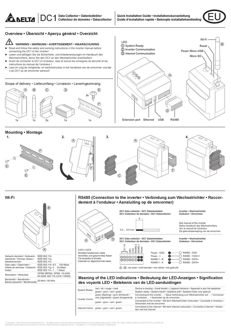
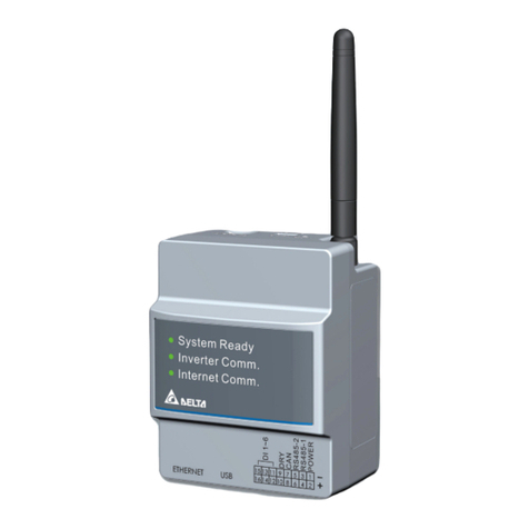
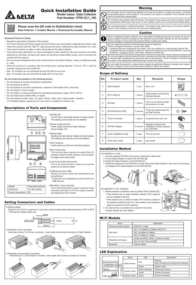
Delta DelREMO-V2.0 User manual

•2

•3
About this guide
Purpose
This guide explains the method to install and configure the DelREMO-V2.0 system. This guide serves as a quick
reference guide for engineers and technicians operating the system.
Intended reader
This guide is written for the trained engineers and technicians to facilitate installation and configuration of the
DelREMO-V2.0 system.
Chapter organization
This guide is organized into the following chapters:
Chapter 1: Introducing handling and safety information describes the basic structure and functionality of the
DelREMO-V2.0 system.
Chapter 2: Introducing DelREMO-V2.0 system gives a broad overview of the various components of the system
and their specifications.
Chapter 3: System installation procedure describes how to install and assemble various components of the
DelREMO-V2.0 system.
Chapter 4: System commissioning describes how to start and configure the DelREMO-V2.0 system.
Chapter 5: Introducing alarm system and troubleshooting explains various alarms and their indications with
standard trouble shooting procedure.
Chapter 6: Maintenance describes the maintenance procedures to be adopted for the DelREMO-V2.0 SYSTEM.
.
Appendix gives additional information about the product.
Instructional icons
Before you start you should familiarize yourself with the instructional icons used in this guide.
WARNING
A WARNING ICON INDICATES SITUATIONS WHICH CAN CAUSE
SEVERE INJURY OR DEATH OR LOSS OF EQUIPMENT.
CAUTION
A CAUTION ICON INDICATES SITUATIONS WHICH CAN CAUSE
DAMAGE TO EQUIPMENT AND PROPERTY.
NOTE
NOTE GIVES USAGE TIPS.

•4
Disclaimers
All information contained in this document is subject to change without prior notice and is provided without
warranty of any kind. The document is not intended for production. All information contained in this document
was obtained in specific environments, and is presented as an illustration. Delta does not hold any warranty or
responsibility for the parts that are not supplied by Delta such as adapter & sensors. Damage caused by such
external parts does not come under warranty.
THE INFORMATION CONTAINED IN THIS DOCUMENT IS PROVIDED ON AN “AS IS” BASIS.
In no event will Delta be liable for damages arising directly or indirectly from any use of the information contained
in this document.
DelREMO-V2.0 system has certain operational limitations which are to be kept in mind before commissioning the
system. DelREMO-V2.0 system is designed to gather data at solar site form sensors and solar inverter and
transmit the same to Delta’s Remote Monitoring Server only. This equipment is not designed for applications
where failure of system could cause loss of life or property.

•5
Table of Contents
1Handling and Safety Information.....................................................................................6
1.1 General Safety Instructions....................................................................................6
1.2 Specific Instructions................................................................................................6
1.3 Additional Information.............................................................................................6
1.4 Contents of the consignment..................................................................................6
1.5 Unpacking the consignment.................................................................................7
1.5.1 Follow check list .....................................................................................................7
1.5.2 Handling tips...........................................................................................................7
1.5.3 Preliminary inspection ............................................................................................7
2DelREMO-V2.0 System Overview ....................................................................................8
2.1 System Description.................................................................................................8
2.2 Introduction to different sections ............................................................................9
2.3 Technical Specifications.......................................................................................10
3Installation procedure.....................................................................................................12
3.1 Steps involved in installation ................................................................................12
3.2 Basic interconnection steps..................................................................................15
4System Commissioning .................................................................................................16
4.1 Steps involved in system commissioning.............................................................16
4.1.1 System start up precautions.................................................................................16
4.1.2 Starting up procedure...........................................................................................16
4.1.3 System Configuration...........................................................................................17
4.1.4 Settings Through LCD..........................................................................................32
4.1.5 Basic functional verification..................................................................................36
4.1.6 Check points before leaving the site ....................................................................36
4.1.7 System calibration procedure...............................................................................37
4.1.8 Conforming the Configuration ..............................................................................37
4.2 Modes of operation ............................................................................................38
4.2.1 Mains Mode..........................................................................................................38
5Introducing alarm system and Troubleshooting .........................................................39
5.1 System Alarms .....................................................................................................39
5.2 Troubleshooting....................................................................................................39
5.2.1 Standard procedure..............................................................................................39
5.2.2 System status indications.....................................................................................39
5.2.3 Troubleshooting .................................................................................................40
5.2.4 Unresolved problems............................................................................................40
6Maintenance.....................................................................................................................41
6.1 General periodic maintenance .............................................................................41
6.2 Do’s and Don’ts ....................................................................................................41
6.3 Customer care support.........................................................................................42
•6
1 Handling and Safety Information
It should be ensured that trained technicians should only operate the DelREMO-V2.0 system. Operating
personnel are advised to read the manual completely before attempting installation. Delta will not be
responsible for any mishaps occurring due to the ignorance of the safety instructions.
1.1 General Safety Instructions
Following are the safety instructions for operating the DelREMO-V2.0 system: -
•Equipment racks may have sharp edges. Wearing gloves is recommended.
•Ensure that the system is connected to DC adapter before operating it.
•Ensure that all operations concerning the DelREMO-V2.0 system are carried out under trained
supervision. Supervisors, who are capable of providing first aid in case of electric shock, need to be
present at the site.
1.2 Specific Instructions
•Before operating the system, please ensure basic parameters like environmental conditions,
AC input frequency and voltage, are as per the system specification.
•Ensure all the AC and DC inputs & outputs are connected to specified MCB’s & Connectors.
•Ensure the temperature sensors are placed at appropriate location where temperature needs to be
monitored.
•The area is freed of any flammable vapors or fluids. To avoid electrical hazard, the outer covers of all
components including the rectifiers are to be tightly secured.
1.3 Additional Information
•Delta does not hold any liability for damages resulting from incorrect installation or poor maintenance
of the system.
•Operation of the equipment beyond its intended purpose could show drastic results.
•Unauthorized modification of the equipment will void the warranty and it may cause incorrect
operation.
•The user is responsible for ensuring that the personnel working with the equipment are provided with
appropriate operational and safety training.
•The user is responsible for ensuring the restricted access of DelREMO-V2.0 system.
•If the power supply to the DelREMO-V2.0 system is not fitted with a disconnecting switch or
equivalent device, the operator is responsible for fitting an appropriate disconnection switch
conforming to the relevant regulations.
1.4 Contents of the consignment
Following table shows the contents of Consignment.
Table 1.1 Contents of the consignment
Sr. No
Product
Remark
1
Installation and quick start guide
1 PCE
2
DelREMO-V2.0 system
1 PCE

•7
1.5 Unpacking the consignment
The instructions given below are to be followed while unpacking the contents of the consignment. Not
following these instructions may cause injury or damage to life and equipment.
1.5.1 Follow check list
•Check the received consignment according to the check list.
•Contact the transport authorities and Delta if any item is missing as per the list of contents.
1.5.2 Handling tips
DelREMO-V2.0 system is light weight equipment; need to be handled very carefully while installing else
may damage internal components.
1.5.3 Preliminary inspection
•Before removing the system from the crate, it needs to be inspected for any damages.
•If any damage is noted, the transport authorities are contacted immediately
•After removing the system from the crate, the system is inspected for any dents or damages.
•If any damage is noted, the transport authorities are contacted immediately.
3
24 VDC, 1.5 Amp Adapter
1 PCE
4
Antenna
1 PCE
5
Installation Accessories
1 SET

•8
2 DelREMO-V2.0 System Overview
DelREMO-V2.0 is remote monitoring unit with several features aimed to gather data from solar sites.
This unit is unique solution for fetching data over various sensors, solar inverter over solar sites.
For safety purpose of the equipments is provided with reverse polarity protection and surge protection
on RS485 data line using IEC 6100-4-5 standards.
Heart of system is built around advanced 32 bit high end RISC controller which manages and controls
different inverter modules to ensure optimal performance and unmatched efficiency. High end PLC
based controller is able to monitor and manage all the sensors and solar inverters at site.
Key features of the system are the configurable no. of solar inverters (up to 60) over two RS485 lines
which make it easy to be installed at small to large solar power plants. User friendly front LCD display
with keys helps in local configuration. LED indication in front provides quick information about alarms
and makes it easy for diagnosis in first attempt.
DelREMO-V2.0 has advance features from its predecessor like, USB host for data log downloading, FW
up gradation, LCD interface for local configuration, 2 Channel RS485 lines for efficient inverter
configuration, 4 nos. of 0 to 10 VDC analog inputs, 4 nos. of 4 to 20 mA analog inputs, 8 nos. of digital
inputs & 2 nos. of digital outputs. The system can also control the actual power generation of solar
inverters through the digital inputs, also user can customize the sensors locally using web-GUI.
2.1 System Description
DelREMO-V2.0 is designed with high end 32 bit RISC processor which collects data from different solar
inverters and sensors, and sends them to remote server using high speed GPRS/GSM modem or LAN
connectivity.
Fig 2.1 Architecture of DelREMO-V2.0 SYSTEM

•9
Line block diagram describes how various devices like inverter, energy meter, sensors will be connected
to DelREMO-V2.0 to make it functional in efficient way.
2.2 Introduction to different sections
Before starting with installation and commission let’s get introduced to the important sections of
DelREMO-V2.0 SYSTEM, showing in fig 2.2. Introduction to different sections will facilitate the
installation procedure.
** Above image may differ from actual supplied system.
Fig 2.2 Isometric view of DelREMO-V2.0
Fig 2.3 Front view of DelREMO-V2.0

•10
The DelREMO-V2.0 supports following features and interfaces:-
•4 nos. of 0 to 10 VDC analog inputs for sensor integration like irradiance, pyranometer, temperature etc.
•4 nos. of 4 to 20 mA DC analog inputs for sensor integration like, wind speed, humidity temperature etc.
•8 nos. of potential free digital inputs for alarm input or inverter power management.
•2 nos. of isolated RS485 communication ports maximum up to 62 devices.
•LCD interface for local configuration & data display.
•LED indication for device function & troubleshooting.
•USB host for FW up-gradation & data log download.
•Supports micro Dual SIM card (2G only).
•Isolated input Power supply.
•Increased data point support
•Send data to server using Ethernet, GSM/GPRS.
•XML configuration for faster customization
•Remote management through E management
•Built in RTC.
•Built in 32MB memory for local data storage & expandable up to 32GB by micor-sd card.
2.3 Technical Specifications
Table 2.1 Input DC supply
Input (DC Supply)
Operating Range
18 ~ 24 VDC (24VDC nominal)
Ultimate capacity
20 Watt (Nominal)
Short Circuit Protection
Yes
Fig 2.4 Bottom view of DelREMO-V2.0
Fig 2.5 Top view of DelREMO-V2.0

•11
Table 2.2 User interface
Table 2.3 General specification
User Interface
System Config.
Using LAN & Keypad
Time and Date
Real time date and Programmable
Event log
>200K
Local Monitoring
Thru Ethernet Port (Embedded Web server) & LCD
General
Op. Temp
0ºc to 60º c
Humidity
95% RH Non Condensing

•12
3 Installation procedure
Installation procedure explains the standard procedures to be followed during the installation of the
DelREMO-V2.0 system. Read the safety instructions and warnings carefully and completely before
initiating the installation procedure.
During the installation procedure ensure that the standard steps are followed strictly. Create a check list
involving the various steps of installation and follow them carefully for the complete and successful
installation of the DelREMO-V2.0 system.
Ignorance of the procedure could lead to incomplete or wrong installation. Unfinished or wrong installation
may cause loss to life and equipment.
3.1 Steps involved in installation
Installation procedure of DELREMO SYSTEM involves the following standard steps. Make sure that these
steps are checked and followed throughout the installation procedure.
•Tools Required
•Preliminary Inspection
•System Mounting
•System Handling
•AC Adapter Connection
•Sensor Integration
•Solar Inverter Integration
Step 1:→Tools and equipment required for installation:
Following tools and equipments are required for the installation of the DELREMO SYSTEM. Use of these
tools facilitate proper installation and prevent any accidents causing situation. Technician attempting the
installation must be provided with these tools and equipment.
Serial
no.
Required Tools
Check
1
Screw driver set.
2
Lugs
3
Insulated Philips head screw driver-blade
size 1/4
4
Insulated slotted screw driver- blade size
1/8
5
Insulated side cutters
6
Insulating glovess
7
Stripper, Cutter
8
Wire crimper

•13
Step 2:→Preliminary system inspection
Before starting with the installation of the system thoroughly inspect the system for any physical damage
during carriage. Contact the carrier company if any physical damage is noticed. Follow the check list to
inspect the system.
Step 3:→System Mounting
DelREMO-V2.0 is fully internally fitted and completely connected at the factory. System mounting and
input/output connections along with necessary connections to various power sources and connections are
made at the installation site. DelREMO-V2.0 is to be mounted on wall
•At first mark two holes on the wall where system has to be installed using the wall mount plate.
•Fix the wall mount plate to the wall as shown in image below.
Serial
no.
Systems for inspection
Check
1
Check the unit for any physical damage to
the system.
2
Check the internal components.
3
Check for any damage to the LCD.
Fig 3.1 DelREMO-V2.0 Wall Mounting Plate

•14
•Move the DelREMO-V2.0 downwards as shown below. Note that slot represented locks
with hooks provided in wall.
Step 4:→System Handling
While opening and closing the top cover of DELREMO system, special attention is required towards LCD
connector, as the top cover may damage LCD’s harness while opening and closing.
Step 5:→Adapter connections
Step 6:→Solar Inverter Modular interconnection procedure
Modular interconnection procedure involves interconnection to various modules of the system on RS 485
daisy chain to make it functional.
WARNING
While connecting the adapter output to DelREMO System polarity
of the supply must be checked. The 24 VDC input to system must
be connected to input terminal provided only.
NOTE
MAXIMUM 30 NUMBERS OF SOLAR INVERTER MODULES CAN BE
CONNECTED OVER RS485 DAISY CHAIN OVER 1 PORT. USE PROVIDED
RS485 TERMINAL BLOCK FOR CABLE TERMINATION AT DELREMO
SYSTEM. THUS MAXIMUM 60 INVERTERS CAN BE CONNECTED OVER 2
RS485 PORTS.
Fig 3.2 DelREMO-V2.0 Wall Mounting Arrangement

•15
3.2 Basic interconnection steps
DelREMO-V2.0 involves the following basic interconnection steps. The following connection check list is
done to avoid connection problems.
Serial
no.
Steps for input connection
Check
1
Connect all the sensors output to
DelREMO at their respective position &
provide power from system is required.
2
Connect inverters over RS485 port,
ACEM.
3
Connect Digital inputs if required.
4
Connect 24 VDC Adapter to the unit.
NOTE
USE THE WIRING DIAGRAM, SUPPLIED WITH THE INSTALLATION
DOCUMENT, TO ENSURE THAT ALL CABLES HAVE BEEN CONNECTED
CORRECTLY.

•16
4 System Commissioning
DelREMO-V2.0 commissioning consists of starting up procedure and calibration of the system.
4.1 Steps involved in system commissioning
Following steps are involved in the commissioning procedure of the DelREMO-V2.0. Follow the stepwise
procedure to avoid any mistakes in the commissioning procedure.
4.1.1 System start up precautions
DelREMO-V2.0 works with 24V DC voltage, extra care should be taken while operating the system. Read
and follow precautions mentioned below carefully while starting up the commissioning of the system.
Ignorance of the precautions can cause serious loss to life or equipment.
4.1.2 Starting up procedure
Check all the wire connections for any damage or loose connections, before starting up procedure of
DelREMO-V2.0. Follow the below step wise procedure strictly for startup procedure of DelREMO-V2.0.
Step wise starting process will prevent probability of any mistake or missing any step.
Serial
no.
Steps for Startup precautions
Check
1
Check all wires again for any possible
loose or wrong connections prior to
commissioning.
2
Check AC supply to adapter unit is
switched to the “Off” position
3
Check the frame ground is properly
connected to a permanent earth ground
connection
4
Check all inverter modules are connecting
in daisy chained array.
5
Check SIM Card is inserted at SIM 1 slot
(If GSM/GPRS data mode to be used)
6
Check Antenna is connected to SMA
connector provided on body. (If
GSM/GPRS data mode to be used)
NOTE
ENSURE ALL TOOLS ARE PROPERLY INSULATED BEFORE USING THEM.
Serial
no.
Starting up procedure
Check

•17
4.1.3 System Configuration
After DelREMO-V2.0 is powered ON, connect the DelREMO to Laptop/PC via Ethernet port provided at the
bottom of unit using RJ45 cable. Following settings are to be done on Laptop/PC to access the DelREMO:
-
I. Click on Start TAB, and then go to Control Panel TAB as Shown below.
II. After Clicking on Control Panel, window will appear as shown, click on Network and sharing
Center.
III. After Clicking on Network and sharing Center, window will appear as shown, click on Change
adapter settings.
IV. After clicking on change adapter settings, the window will appear as shown; right click on the
icon
“Local area connection”as shown below.
V. Now click on properties as highlighted.
VI. After clicking Properties window will appear as shown, select Internet Protocol Version 4
(TCP/IPv4), then clicks on properties (highlighted in yellow).
VII. After clicking on properties window will appear as below and select “Use the following IP
address”. Now do setting as provided in below snapshot, after doing setting click on OK Tab.
IP Address
:
192.168.100.1
Subnet Mask : 255.255.255.0
1
Check input supply to adapter is
switched ON.
2
Check for output 24VDC voltage at the
output of adapter.
3
Check for LED operation of DelREMO-
V2.0

•18

•19
VIII. T
o
t
u
r
n off proxy settings go to (PATH: Control Panel>Internet Option)
IX. At Internet Properties TAB click on Connections, then click on LAN Settings TAB.
a. Un-tick Proxy server.
b. Click on OK. As shown in figure.
NOTE
TURN OFF ALL PROXY SETTING & FIREWALL BEFORE PROCEEDING
TO NEXT
STEP.

•20
X. Now open Google Chrome browser on your laptop.
XI. In Address Bar type the following IP address 192.168.100.30 and press Enter Key.
Pushpak II Controller Web
page configuration
Table of contents
Other Delta Data Logger manuals

Delta
Delta PPM DC1 100 Series User manual

Delta
Delta PPM DC1 100 Series Specification sheet

Delta
Delta HD207 Series User manual

Delta
Delta DC1 User manual

Delta
Delta DC1 User manual

Delta
Delta PPM DC1_100 Series User manual

Delta
Delta DC1 User manual

Delta
Delta PPM DC1_100 Series Instruction manual

Delta
Delta DC1 User manual

Delta
Delta Data Collector PPM DC1-100 User manual
Popular Data Logger manuals by other brands

EasyLog
EasyLog EL-USB-ACT quick start guide

Dostmann Electronic
Dostmann Electronic LOG200 Series operating instructions

ThermoFisher Scientific
ThermoFisher Scientific DataTaker DT90 Series user manual

LOVATO ELECTRIC
LOVATO ELECTRIC DMK40 Software manual

MadgeTech
MadgeTech TEMP1000EX user guide

Odyssey
Odyssey Xtreem user manual