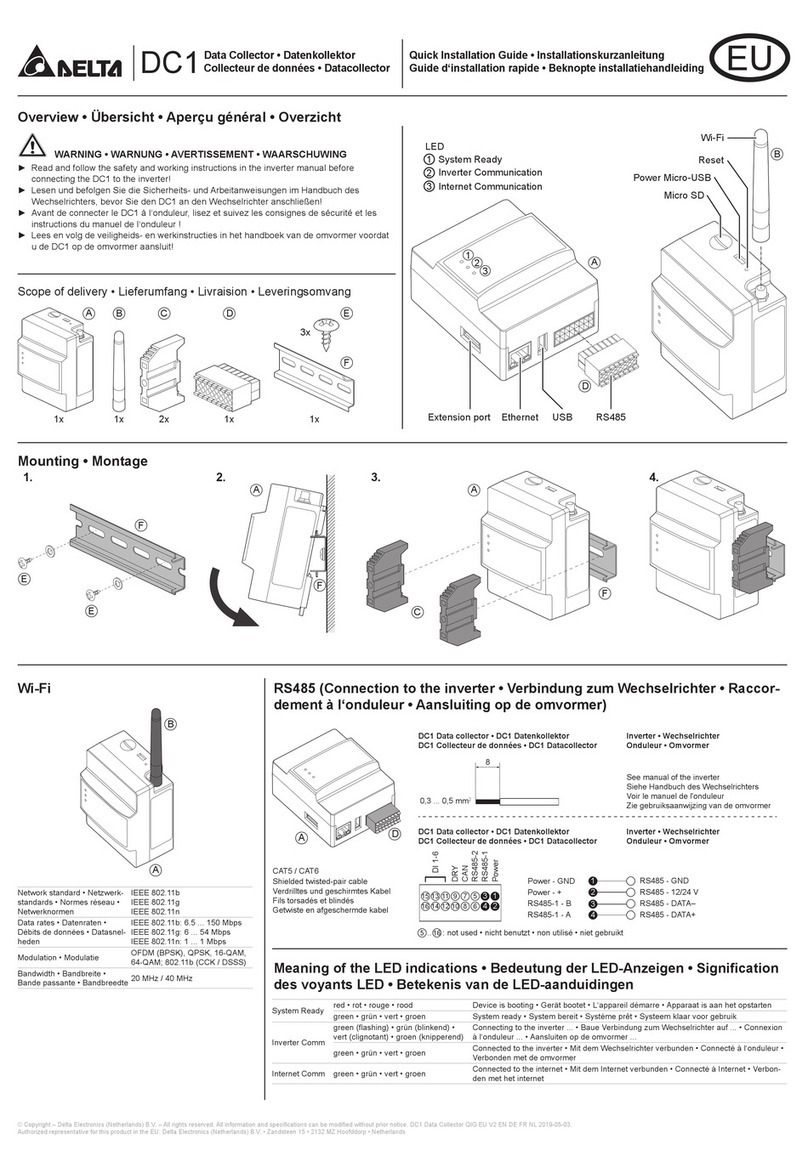
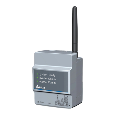
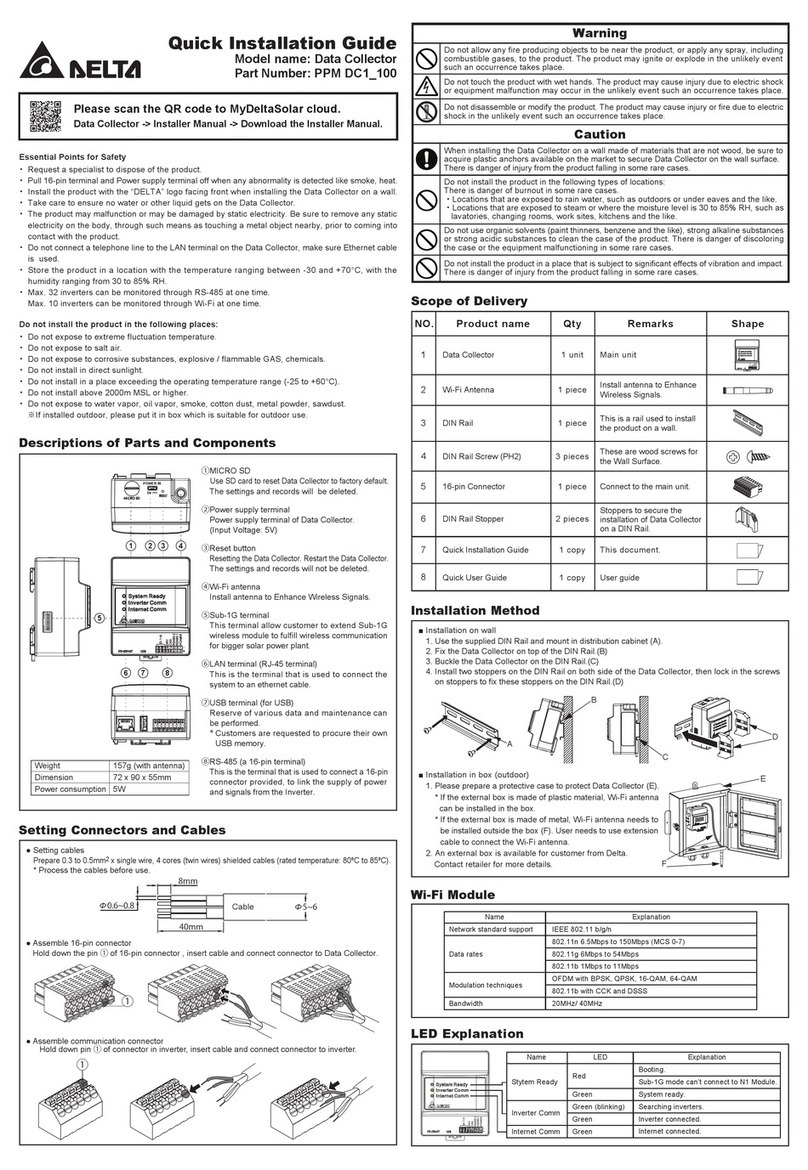
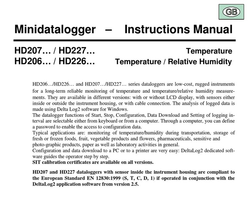
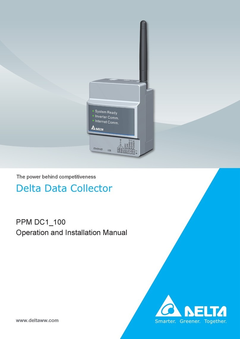
Delta PPM DC1 100 Series User manual

PPM DC1_100
Installation Manual
Delta Data Collector
The power behind competitiveness
www.deltaww.com

■ Introduction ■
Precautions for Your Safety
Essential Points for Safety
Precautions for Use
Product Overview
1. Preparation before construction
1.1.Scope of Delivery
1.2.Dimension
1.3.Descriptions and Functions of Parts and Components
1.4.Reset Method
1.5.Description of Functional Pins
2. Installation
2.1.Installation on wall
2.2.Installation in box (outdoor)
2.3.Connection to the inverter
2.4.Download the APP
3. System application
3.1.Normal mode
3.2.Retrofit mode
3.3. 3rd party monitoring - Modbus tcp/ip
3.4. 3rd party monitoring - Modbus RTU (Forward mode)
4. Specifications
5. When Something Seems Wrong (Troubleshooting)
5.1.Error Displays
5.2.Troubleshooting
Appendix - PPM P1_120
Appendix - PPM P3_120
03
04
04
05
06
06
07
08
09
09
10
10
10
11
12
13
13
14
16
17
19
20
20
21
22
23
Contents
. . . . . . . . . . . . . . . . . . . . . . . . . . . . . . . . . . . . . . . . . . . . . . . . . . . .
. . . . . . . . . . . . . . . . . . . . . . . . . . . . . . . . . . . . . . . . . . . . .
. . . . . . . . . . . . . . . . . . . . . . . . . . . . . . . . . . . . . . . . . . . . . . . . . . . . . . . . . .
. . . . . . . . . . . . . . . . . . . . . . . . . . . . . . . . . . . . . . . . . . . . . . . . . . . . . . . . . . . .
. . . . . . . . . . . . . . . . . . . . . . . . . . . . . . . . . . . . . . . . . . . . . . . . . . . . . .
. . . . . . . . . . . . . . . . . . . . . . . . . . . . . . . . . . . . . . . . . . . . . . . . . . . . .
. . . . . . . . . . . . . . . . . . . . . . . . . . . . . . . . . . . . . . . . . . . . . . . . . . . . . . . . .
. . . . . . . . . . . . . . . . . . . . . . . . . . . . . . . . . . . . . . . . . . . . . . . . . . . . . . .
. . . . . . . . . . . . . . . . . . . . . . . . . . . . . .
. . . . . . . . . . . . . . . . . . . . . . . . . . . . . . . . . . . . . . . . . . . . . . . . . . . .
. . . . . . . . . . . . . . . . . . . . . . . . . . . . . . . . . . . . . . . . . . . . . . . . . . . .
. . . . . . . . . . . . . . . . . . . . . . . . . . . . . . . . . . . . . . . . . . . . . .
. . . . . . . . . . . . . . . . . . . . . . . . . . . . . . . . . . . . . . . . . . . . . . . . . . . . . . .
. . . . . . . . . . . . . . . . . . . . . . . . . . . . . . . . . . . . . . . . . . . . . . . . . . . . . . .
. . . . . . . . . . . . . . . . . . . . . . . . . . . . . . . . . . . . . . . .
. . . . . . . . . . . . . . . . . . . . . . . . . . . . . .
. . . . . . . . . . . . . . . . . . . . . . . . . . . . . . . . . . . . . . . . . . . .
. . . . . . . . . . . . . . . . . . . . . . . . . . . . . . . . . . . . . . . . . . . . . . . . .
. . . . . . . . . . . . . . . . . . . . . . . . . . . . . . . . . . . . . . . . . . . . . . . . . . . . . . . . . . . . . . .
. . . . . . . . . . . . . . . . . . . . . . . . . . . . . . . . . . . . . . . . . . . . . . . . . . . . . . .
. . . . . . . . . . . . . . . . . . . . . . . . . . . . . . . . . . . . . . . . . . . . . . . . . . . . .
. . . . . . . . . . . . . . . . . . . . . . . . . . . . . . . . . . . . . . . . . . . . . . . . . . . . . . . . . . . . .
. . . . . . . . . . . . . . . . . . . . . . . . . . . . . . . . . . . .
. . . . . . . . . . . . . . . . . . . . . . . . . . . . . . . . . . . . . . . . . . . . . . . . . . . . . . . .
. . . . . . . . . . . . . . . . . . . . . . . . . . . . . . . . . . . . . . . . . . . . . . . . . . . . . . . .
. . . . . . . . . . . . . . . . . . . . . . . . . . . . . . . . . . . . . . . . . . . . . . . . . . . . . . . . . .
2

This Instruction Manual provides precautions with the following notations and symbols for safe use of the PPM DC1_100.
The expression “Product”, “Data Collector” or “DC1” refers to the PPM DC1_100. Precautions described herein contain important
aspects of safety.
Please observe and follow these descriptions.
Notations and symbols are described below:
■ Notations for safe use of the product and their meanings
Precautions for Your Safety
Failing to handle the Product properly may result in the described danger leading to slight or
intermediate level injuries and in some cases may also result in serious injury or death.
Failing to handle the Product properly may result in the described danger leading to slight or
intermediate level injuries or property damages in some instances.
■ Explanation of graphic symbols
● Electric Shock Precaution
Notifications pertaining to precautions for potential electric shock,
under specific conditions
● General
Unspecified general notifications pertaining to prohibited actions.
● Disassembly prohibited
Notifications pertaining to prohibition of equipment disassembly,
when doing so can potentially lead to injuries such as electric shock.
● General
Unspecified general notifications pertaining to instructions for users
Warning
Caution
When wiring the power meter, make sure to turn OFF the breakers connected to the power meter. Although small,
there is a risk of electric shock.
Do not touch the Product with wet hands.
The Product may cause injury due to electric shock or equipment malfunction may occur in the unlikely event
such an occurrence takes place.
When installing the DC1, make sure to turn OFF all solar generator breakers and direct current switches for the
inverter.
Although small, there is a risk of electric shock.
Do not disassemble or modify the Product.
The Product may cause injury or fire due to electric shock in the unlikely event such an occurrence takes place.
Do not allow any fire producing objects to be near the Product, or apply any spray, including combustible gases,
to the Product. The Product may ignite or explode in the unlikely event such an occurrence takes place.
Warning
3

When installing the DC1 on a wall made of materials that are not wood,
be sure to acquire plastic anchors available on the market to secure the Wall
Surface Mounting Plate on the wall surface. There is danger of injury from
the Product falling in some rare cases.
Caution
Do not install the Product in a place that is subject to significant effects of vibration
and impact. There is danger of injury from the Product falling in some rare cases.
Do not use organic solvents (paint thinners, benzene and the like), strong alkaline
substances or strong acidic substances to clean the case of the product. There is
danger of discoloring the case or the equipment malfunctioning in some rare cases.
Securely tighten the screws using a torque of 0.98 N.m.
Although small, there is a risk of burns due to defective connections.
Do not tighten the wiring using electric tools (drills), whose main purpose is to open
holes, such as impact drivers, etc.
Do not install the Product in the following types of locations:
There is danger of burnout in some rare cases.
・
Locations that are exposed to rain water, such as outdoors or under eaves and the like.
・Locations that are exposed to steam or where the moisture level is 30 to 85% RH,
such as lavatories, changing rooms, work sites, kitchens and the like.
Items described below must be followed as they are necessary to secure safety.
・Request a specialist to dispose of the product.
・Pull 16-pin terminal and Power supply terminal off when any abnormality is detected like smoke, heat.
・Install the product with the “DELTA” logo facing front when in stalling the Data Collector on a wall.
・Take care to ensure no water or other liquid gets on the Data Collector.
・The product may malfunction or may be damaged by static electri city. Be sure to remove any static electricity on the body,
through such means as touching a metal object nearby, prior to coming into contact with the product.
・Do not connect a telephone line to the LAN terminal on the Data Collector, make sure Ethernet cable is used.
・
Store the product in a location with the temperature ranging be tween -30 and +70°C, with the humidity ranging from 30 to 85% RH.
・Max. 32 inverters can be monitored through RS-485 at one time.
Max. 9 inverters can be monitored through Wi-Fi at one time.
Do not install the product in the following places:
・Do not expose to extreme fluctuation temperature.
・Do not expose to salt air.
・Do not expose to corrosive substances, explosive / flammable GAS, chemicals.
・Do not install in direct sunlight.
・Do not install in a place exceeding the operating temperature range (-25 to +55°C).
・Do not install above 2000m MSL or higher.
・Do not expose to water vapor, oil vapor, smoke, cotton dust, metal powder, sawdust.
※If installed outdoor, please put it in box which is suitable fo r outdoor use.
Essential Points for Safety
・The Product may malfunction or may be damaged by static electricity. Be sure to remove any static electricity on the body,
through such means as touching a metal object nearby, prior to coming into contact with the Product.
・
Store the Product in a location with the temperature ranging between -20 and +55°C, with the humidity ranging from 30 to 85% RH.
・The Product communicates wirelessly.
Install the Product as far away as possible from devices that emit strong radio waves, such as a civil band radio equipment.
・
The communication performance varies depending on the peripheral environment. Verify in advance that the Product is communicating
normally when installing the Data Collector on a wall.
・Avoid installing the Data Collector near iron plate or steel reinforcements and try to install the Product with as much clear space
as possible.
Precautions for Use
4
Product Overview
● Partial / Zero export for grid protection
● DeltaSolar APP for inverter monitoring and control
● MyDeltaSolar cloud service or 3rd party platform compatible
● 7 days local data storage prevents data loss
● Wi-Fi, Ethernet and RS-485 communication interface
■ Features
■ System Architecture
DC1 data collector is designed for monitoring PV inverter and conducting partial / zero export application to ensure solar power
will feed in base on power company requirement. With its wired and wireless communication interface, DC1 can be connected to
either MyDeltaSolar or 3rd party cloud service to realize remote management and optimize the efficiency of the PV system.
Residential
Commercial
Partial / Zero export
Solar Panel
Solar Panel
Grid
3rd Party Monitoring Platform
HxA Series Inverter
CT
DC1
Three
Phase
Inverter
*Only one communication protocol (LAN, Ethernet, Wi-Fi) can be used at
the same time.
DC Power
AC Power
RS-485
EthernetP2P
LAN Wi-Fi
MyDeltaSolar Cloud Service (Monitoring)
Cloud
3rd Party Monitoring Platform
MyDeltaSolar Cloud Service (Monitoring)
Cloud
MyDeltaSolar Cloud Service (Monitoring)
Cloud
Solar Panel
Three Phase Inverter
Load
Charging TV Refrigerator Light
Load
Charging TV Refrigerator Light
CT
P1+DC1
P3+DC1
DeltaSolar
(Real-Time)
Karapinar
38.8 kWh -- kWh
IBARAKI
Tainan,Taiwan
20.4 kWh
Chiayi,Taiwan
Floating
Tainan,Taiwan
Feed-in
3.22 3.00
Grid
DeltaSolar
(Real-Time)
Karapinar
38.8 kWh -- kWh
IBARAKI
Tainan,Taiwan
20.4 kWh
Chiayi,Taiwan
Floating
Tainan,Taiwan
Feed-in
3.22 3.00
Grid
DeltaSolar
(Real-Time)
Karapinar
38.8 kWh -- kWh
IBARAKI
Tainan,Taiwan
20.4 kWh
Chiayi,Taiwan
Floating
Tainan,Taiwan
Feed-in
3.22 3.00
5

Verify that following items are available for use prior to using this feature.
1.
Preparation before construction
1.1.Scope of Delivery
6
NO.Product name QtyRemarksShape
Data Collector
DIN Rail
DIN Rail Screw (PH2)
16-pin Connector
DIN Rail Stopper
This is a rail used to install the product on a wall.
These are wood screws for the Wall Surface.
Connect to the main unit.
1
3
4
5
6
1 unitMain unit
1 piece
Wi-Fi Antenna Install antenna to Enhance Wireless Signals.2 1 piece
3 pieces
2 pieces
1 piece
Quick Installation Guide7 1 copy Installation Guide
Stoppers to secure the installation of Data Collector
on a DIN Rail.

72mm
90 mm
170 mm
117 mm
121 mm
55 mm
unit: mm
1.2.Dimension
DC1
Din Rail
125±1
25
13.5±0.5 18 7
5.2±0.2
7.5
35
7

1.3.
Descriptions and Functions of Parts and Components
POWER IN
5V
1 32
5 76
4
①MICRO SD
Use SD card to reset Data Collector to factory default.
The settings and records will be deleted.
②Reset button
Resetting the Data Collector. Restart the Data Collector.
The settings and records will not be deleted.
③Wi-Fi antenna
Install antenna to Enhance Wireless Signals.
④Extend terminal
It is also possible to expand the matching Power Meter for measurement.
⑤LAN terminal (RJ-45 terminal)
This is the terminal that is used to connect the system to an
ethernet cable.
⑥USB terminal (for USB)
Reserve of various data and maintenancecan be performed.
*Customers are requested to procure their own USB memory.
⑦RS-485 (a 16-pin terminal)
This is the terminal that is used to connect a 16-pin connector
provided, to link the supply of power and signals from the Inverter.
LED Explanation
Modulation techniques
Bandwidth
Explanation
IEEE 802.11 b/g/n
802.11n 6.5Mbps to 150Mbps (MCS 0-7)
802.11g 6Mbps to 54Mbps
802.11b 1Mbps to 11Mbps
OFDM with BPSK, QPSK, 16-QAM, 64-QAM
802.11b with CCK and DSSS
20MHz/ 40MHz
Name
Network standard support
Data rates
Wi-Fi Module
Name
Internet Comm
Inverter Comm
System Ready
LED
Green (blinking ON 3s / OFF 3s)
Green (blinking ON 1.5s / OFF 1.5s)
No light
Green
Green (blinking ON 1s / OFF 1s)
Green
Red
Explanation
Cloud connection status
APP connection status
Network not connected
Network connected
Inverter connected.
System ready.
Booting.
8

1.4.Reset Method
1.5.Description of Functional Pins
POWER IN
5V
Press reset button System ready led flashing Action of DC1
3~5 sec 0.5sec ON, 0.5sec OFF Rebuild wifi module
6~10 sec 1sec ON, 1sec OFF Reset wifi password and
rebuild wifi module
Over 15sec 2sec ON, 2sec OFF Reset DC1 setting without SN,
then reboot
1
2
3
4
5
6
7
8
9
10
11-16
Definition of general Pins
*Dry Contact can support operating condition up to 24Vdc/0.3A
Pins Description
Power Input GND
Power Input +
RS485 1 - B (communication with inverters)
RS485 1 - A (communication with inverters)
RS485 2 - B (forward mode function)
RS485 2 - A (forward mode function)
N/A
N/A
Dry Contact*
Dry Contact*
Digital Input (DI 1 - 6)
16&15
16&14
16&13
16&12
16&11
Definition of Digital Input (DI 1-6)
Short
Pins
System Behavior
(Standard)
System Behavior
(Australia)
N/A Emergency power off (EPO)
Power de-rating to 75%
Power de-rating to 100%
Power de-rating to 50%
Power de-rating to 0%
Power de-rating to 30%
Power de-rating to 0%
Power de-rating to 100%
Power de-rating to 60%
Power
RS485-1
RS485-2
CAN
DRY
DI 1-6
1
2
35
79111315
6
810121416 4
TOP VIEW
9

2.Installation
2.1.Installation on wall
(1)Use the supplied DIN Rail and mount in distribution cabinet (A).
(2)Fix the Data Collector on top of the DIN Rail.(B)
(3)Buckle the Data Collector on the DIN Rail.(C)
(4)Install two stoppers on the DIN Rail on both side of the Data Collector, then lock in the screws on stoppers to fix these stoppers
on the DIN Rail.(D)
C
B
AD
2.2.Installation in box (outdoor)
(1)Please prepare a protective case to protect Data Collector (E).
* If the external box is made of plastic material, Wi-Fi antenna can be installed in the box.
* If the external box is made of metal, Wi-Fi antenna needs to be installed outside the box (F).
User needs to use extension cable to connect the Wi-Fi antenna.
(2)An external box is available for customer from Delta. Contact retailer for more details.
E
F
10

2.3.Connection to the inverter
(1) Prepare 0.3 to 0.5mm²single wire, 4 cores (twin wires) shielded cables (rated temperature: 80ºC to 85ºC).
8mm
Cable
40mm
Φ0.6~0.8 Φ5~6
(2) Hold down both side ① of the 16-pin connector, insert cables and then connect to Data Collector.
①
(3) Remove the RS-485 communications connectors from the inverter, and thread the cables through the waterproof gasket.
Terminal switch ON1 (OFF) 1 (OFF)
inverter with farthest
connection from the
Data Collector
Communications
connector
Communications
cables
Terminal
switch
ON
1
Power
RS485-1
RS485-2
CAN
DRY
DI 1-6
1
2
35
79111315
6
810121416 4
1
2
3
4
DATA–
DATA+
GND
12/24 V
Power - GND
Power - +
RS485-1 - B
RS485-1 - A
InverterDC1
16pin connector RS-485
* Process the cables before use.
Shielded twisted-pair cable
CAT5 / CAT6
16-pin
connector
DC1
comm.
connector
Inverter
(4) Hold down side ②of the communication connector in the inverter, insert the cables connected to the DC1 16-pin connector.
②
ON
RS485-B
RS485-A
GND
+12V
Communications
connector
Communications
connector
Communications
connector
Inverter 2 Inverter XInverter 1
16-pin connector
DC1
ON
1
Set to OFF
ON
1
11 1
Set to OFF
ON
1
Set to ON
ON ON
11

2.4.Download the APP
DeltaSolar
1. This APP should collocate with Delta Inverter.
2. If inverter is not connected to cloud, you still can monitor inverter by APP.
Where can search for DeltaSolar APP?
- QR Code: Please scan the QR code to MyDeltaSolar cloud.
- IOS system: Please search “DeltaSolar” in App store.
- Android system: Please search “DeltaSolar” in Google Play.
QR Code
- Please ensure the smart phone is connected to the Internet and the communication is good.
- Before setting up, please registered and sign in once in an internet-connected environment.
ATTENTION
iOS
Android
About OS version
iOS: 8.0 and above
Android OS: Android 8.0 and above
12

3.DC1 system application
When 3rd party monitoring and delta cloud monitoring are using at same time, suggest to add below IP into network white list to
make sure remote function and cloud monitoring work normal.
Back end remote function IP : 52.187.179.41 / Cloud monitoring IP : 52.237.74.126
Suggest 3rd party monitoring system can enable VPN or Port forwarding function of the local router, so Delta service will able to
remote debug when needed.
The RS-485 Inverter is set by operating the DC1 through the APP. Upload power generation data to Cloud Server for monitoring.
P2P
connection
Grid
Web browser (Cloud)
DC1
PV array
Three phase inverter
RS-485Power line Wi-Fi
Ethernet
RS-485
Wi-Fi
P2P
connection
Load
Grid
Flex series inverter
TV Refrigerator Light
RS-485Power line Wi-Fi
Ethernet
PV array
The WI-FI Inverter is set by operating the DC1 through the APP. Upload power generation data to Cloud Server for monitoring.
CT
P1 + DC1
3.1.Normal mode
Inverter connect with DC1 via Wired (RS-485) or Wi-Fi, DC1 transfer inverter data to Delta Cloud.
DeltaSolar App
(Real-Time)
Karapinar
38.8 kWh -- kWh
IBARAKI
Tainan,Taiwan
20.4 kWh
Chiayi,Taiwan
Floating
Tainan,Taiwan
Feed-in
3.22 3.00
DeltaSolar App
(Real-Time)
Karapinar
38.8 kWh -- kWh
IBARAKI
Tainan,Taiwan
20.4 kWh
Chiayi,Taiwan
Floating
Tainan,Taiwan
Feed-in
3.22 3.00
DeltaSolar App (Cloud)
Web browser (Cloud)
DeltaSolar App (Cloud)
Cloud
Cloud
13

Wired: max 32 inverters
Wi-Fi: max 9 inverters
Mixed: max 32 inverters
● Connection type DC1 - Router
Ethernet or Wi-Fi
● Connection type DC1 - Smartphone
Wi-Fi
Note
One of the connected inverters must have RS485 ID (Inverter ID) = 1
3.2.Retrofit mode
Converts data into SOLIVIA protocol.
Connection type
Solivia G3
Solivia G4
RPI HxA
HXA_2xx
not available not available
Wired (RS-485) Wi-Fi Mixed
Connection type
Solivia G3
Solivia G4
RPI HxA
HXA_2xx
M6/8/10A
M15/20A
M30A
M50A_12s
M88H
M15/20/30A_2xx
M50/70A_2xx
M100_210
M100A_280
M125HV
MixedWired (RS-485) Wi-Fi
14

Note
One of the connected inverters must have RS485 ID (Inverter ID) = 1
3.2.Retrofit mode
This function is only for Solivia Gateway, the Wi-Fi inverter is set by DC1 through the APP.
Start Solivia Gateway to monitor on Solivia Cloud.
Connection type
Solivia G3
Solivia G4
RPI HxA
HXA_2xx
not available not available
Wired (RS-485) Wi-Fi Mixed
RS-485Power line
Wi-FiEthernet
PV array ID 1
ID 2
ID 3
ID 4
ID 5
PV array
PV array
PV array
PV array
Solivia
HxA Wi-Fi
HxA Wi-Fi
RPI-M15/20A
RPI M6/8/10A
Solivia Cloud
Solivia Gateway
DC1
15

RS-485
3.3. 3rd party monitoring - Modbus tcp/ip
RS-485 or Wi-Fi inverter is set by DC1 through the APP.
After the setting is completed, the third-party monitoring reads the communication address of DC1 through Modbus to get
the power generation data.
P2P
connection
Grid
DC1
PV array
Three phase inverter
RS-485Power line LAN
3rd Party
Monitoring Platform
Modbus tcp/ip
LAN
DeltaSolar App
(Real-Time)
Karapinar
38.8 kWh -- kWh
IBARAKI
Tainan,Taiwan
20.4 kWh
Chiayi,Taiwan
Floating
Tainan,Taiwan
Feed-in
3.22 3.00
LAN
BOTTOM
VIEW
DC1
Data collector
16

Two Separated
RS-485 port
3rd Party device Delta inverter
Power
RS485-1
RS485-2
CAN
DRY
DI 1-6
1
2
35
79111315
6
810121416 4
DC1 16 pin connector
8
0.3 ~ 0.5 mm2
3.4 3rd party monitoring - Modbus RTU (Forward mode)
3rd Party
Monitoring Platform
3rd party monitoring device with Delta Modbus RTU protocol address built in can be used.
DC1 is master of inverters, also the slave of 3rd party monitoring device.
Grid
PV array
Three phase inverter
RS-485Power line LAN
Modbus RTU (Forward mode)
RS-485
RS-485
DC1
P2P
connection
DeltaSolar App
(Real-Time)
Karapinar
38.8 kWh -- kWh
IBARAKI
Tainan,Taiwan
20.4 kWh
Chiayi,Taiwan
Floating
Tainan,Taiwan
Feed-in
3.22 3.00
17

- When forward mode is enable, DC1 will not able to deliver monitoring data to cloud and APP.
ATTENTION
https://mydeltasolar.deltaww.com/index.php?p=manual
For details, please go to the following link for the APP operation manual.
DeltaSolar APP Operation Manual:
18

ELECTRONIC SPEC
Operating voltage range
Max. Power Consumption
COMMUNICATION
Wired
Wireless
REGULATION
Safety Standard
Emission (EMI)
CONNECTION
GENERAL INFORMATION
LED Display
Operation temperature
Relative humidity
Dimension (WxHxD)
Weight
PPM DC1_100
9Vdc ~ 25Vdc (power port, can be supplied from inverter)
5 Watt
RS-485/ Ethernet
Internal Wi-Fi Module 802.11a/b/g/n
EN 61010-1, CE compliance
EN 300 328, LP0002, Part 15C, Telec T66, KC
Immunity(EMS)
I/O Port
EN 301 489-1/-17, EN 55024, EN 55032, FCC Part 15B
2 pin terminal block for Power Port
4 pin terminal block for RS-485
2 pin terminal block for Can Bus
2 pin terminal block for Dry Contact
6 pin terminal block for digital inputs
RJ-45 connector for Ethernet
USB Port for data storage
System Ready, Inverter Comm., Internet Comm.
-25°C ~ 60°C
30% ~ 85%
72 x 90 x 55 mm
160g (with Wi-Fi antenna)
4. Specifications
19
•Data monitoring:
Able to monitoring data from inverter to cloud or 3rd party monitoring system.
•Connection & Grid setting :
Support initial or function setting for inverter.
•Firmware Update:
Available to update FW by APP or USB for inverter and DC1 itself.
•BACKUP/RESTORE:
Backup the connection setting of DC1, after replacement of DC1 just need to restore the data back no need to set from the beginning.
•REPLACE INVERTER:
This function support change connection setting of DC1, after replace the inverter with new one.
•DRM0 (Digital input) :
This function can set inverters to specific power limit by shorten the corresponding connections.
•PARTIAL/ZERO EXPORT:
This function support dynamic output control application.
•DRY CONTACT :
When enable this function, the dry contact relay inside DC1 will close to trigger external device.
•PHASE INTERLOCK:
Only for AU market, turn on when needed. If one of the inverter lose communication with DC1, other inverter will also remote off.
DC1 Functions
For details, please go to the following link for the APP operation manual.
DeltaSolar APP Operation Manual: https://mydeltasolar.deltaww.com/index.php?p=manual

5.
When Something Seems Wrong (Troubleshooting)
5.1.Error Displays
When a problem occurs, confirm the Error message from the [ERROR EVENTS LOG] page of [History].
Details can be verified in the “ERROR EVENTS LOG” pages.
Refer to the Manual of the Inverter for details on the error codes.
20
Other manuals for PPM DC1 100 Series
1
Table of contents
Other Delta Data Logger manuals

Delta
Delta DC1 User manual

Delta
Delta PPM DC1_100 Series Instruction manual

Delta
Delta Data Collector PPM DC1-100 User manual

Delta
Delta DC1 User manual

Delta
Delta HD207 Series User manual

Delta
Delta PPM DC1_100 Series User manual

Delta
Delta DC1 User manual

Delta
Delta DC1 User manual

Delta
Delta PPM DC1 100 Series Specification sheet

Delta
Delta DelREMO-V2.0 User manual