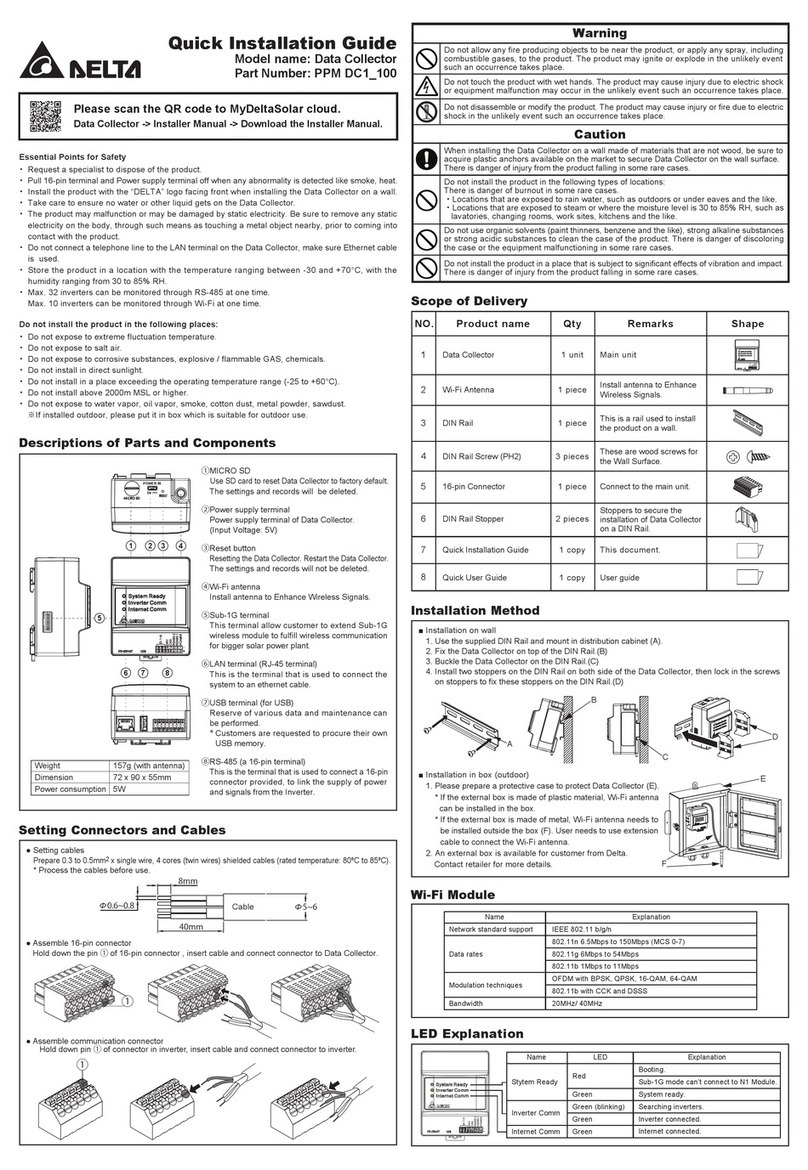
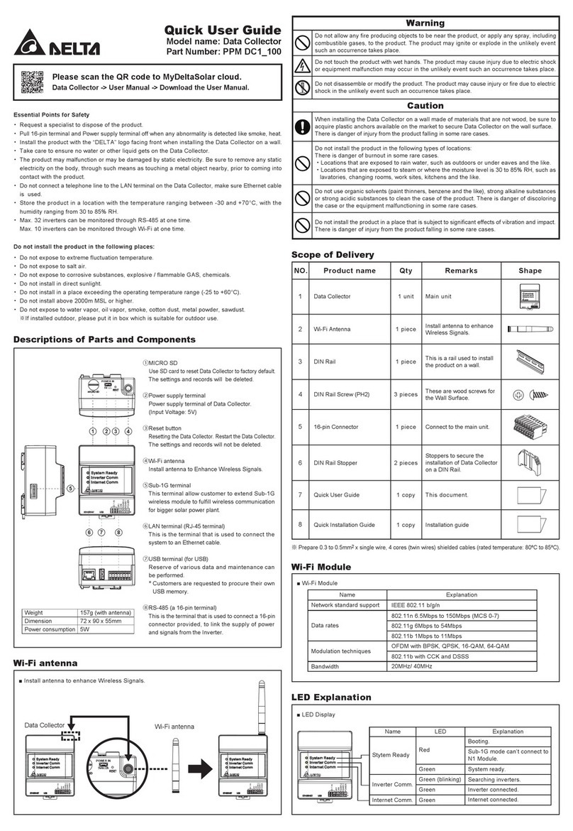
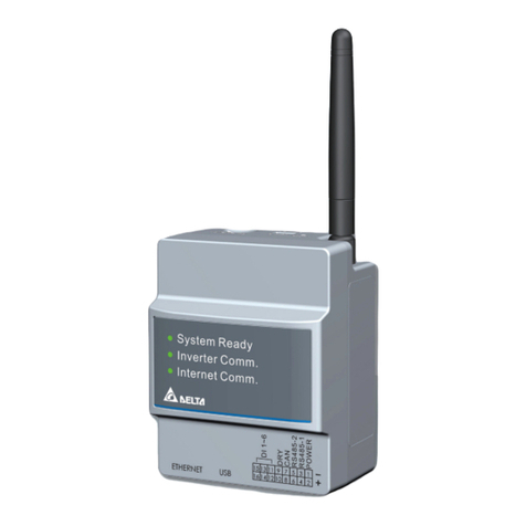
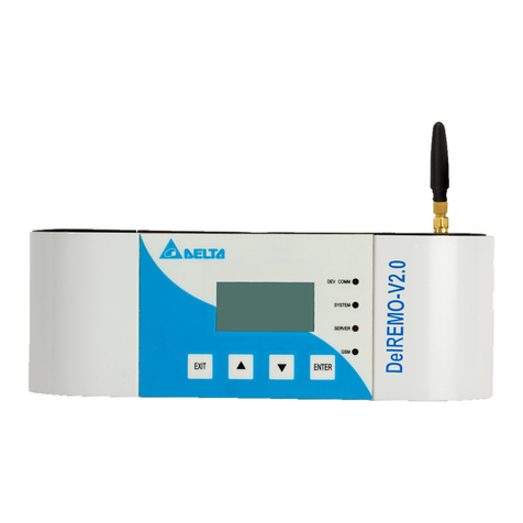
Delta HD207 Series User manual

Minidatalogger – Instructions Manual
HD207… / HD227… Temperature
HD206… / HD226… Temperature / Relative Humidity
HD206…/HD226… and HD207…/HD227… series dataloggers are low-cost, rugged instruments
for a long-term reliable monitoring of temperature and temperature/relative humidity measure-
ments. They are available in different versions: with or without LCD display, with sensors either
inside or outside the instrument housing, or with cable connection. The analysis of logged data is
made using Delta Log2 software for Windows.
The datalogger functions of Start, Stop, Configuration, Data Download and Setting of logging in-
terval are selectable either from keyboard or from a computer. Through a computer, you can define
a password to enable the access to configuration data.
Typical applications are: monitoring of temperature/humidity during transportation, storage of
fresh or frozen foods, fruit, vegetable products and flowers, pharmaceuticals, sensitive and
photo-graphic products, paper as well as laboratory activities in general.
Configuration and data download to a PC or to a printer are very easy:DeltaLog2 dedicated soft-
ware guides the operator step by step.
SIT calibration certificates are available on all versions.
HD207 and HD227 dataloggers with sensor inside the instrument housing are compliant to
the European Standard EN 12830:1999 (S, T, C, D, 1) if operated in conjunction with the
DeltaLog2 application software from version 2.5.
2
52 36
16 5
889
Display
Keyboard
cover
Temperature or
temperature/
humidity
external sensor/s
External
temperature
sensor
Built-in
temperature
sensor
Socket
for RSR232C or for
external probes

3
Description
4
1
8
5
3
11
2
10
12
-199.9
HD207 HD207-1
13 16
Alarm Log
HD226... HD227...
14 17
15 18
4
1
8
5
37
26
9
-199.9
HD206-1 HD206-2
1) Low battery: low battery indication
2) ALRM symbol (ALARM): when alarms are active, it indicates that one or more than one of
the acquired values have exceeded set limits.
3) LOG symbol (LOGGING): it flashes when logging.
4) T1 ON/OFF and ENTER key: it switches the instrument on and off; when programming, it
confirms the step of the current program.
5) T2 LOG key (LOGGING): it starts and stops data acquisition
6) %RH symbol: it indicates that the display is showing a relative humidity measure
7) °C/°F symbol: it indicates that the display is showing a temperature measure (°C / °F selec-
tion is made from PC)
8) T4 PROG and key : this key is used to access the instrument different programming steps;
when programming, it decreases the displayed value.

4
9) T3 F1/F2 and key: in HD206-1 and HD206-2 models, it selects the variable to be dis-
played between temperature (fixed) and relative humidity (fixed) or both of them, alternately.
When programming, it increases the displayed value.
10) Te symbol: it indicates that the display is showing the temperature of the external probe (op-
tional).
11) Ti symbol: it indicates that the display is showing the temperature of the built-in sensor.
12) T3 F1/F2 and key: in HD207 and HD207-1 models, it selects the variable to be displayed
between internal temperature (fixed), external one (fixed) or both of them, alternately. When
programming, it raises the displayed value.
13) Alarm LED (ALARM): the red LED flashes to indicate that one or more acquired values have
exceeded the set-point and/or that battery is flat. During the battery test, it produces a series of
close flashings indicating that battery is low and that it has to be replaced as soon as possible.
14) T1 ON/OFF and LOGGING key: it starts and stops a logging session .
15) T2 Key not used.
16) LOG LED (Logging): the green LED flashes when the instrument is logging. During the bat-
tery test, it produces a series of close flashings indicating that the battery is charged.
17) T4 BATTERY TEST key: key to be used to check the battery level. If the battery is charged,
the green LED (LOG) makes a series of close flashings. If it is low, the red LED (Alarm)
flashes.
18) T3 Key not used

5
Keyboard Protection Cover
All datalogger models are provided with a 4-key keyboard:
in HD226… and HD227… the two central keys are not
used. The keyboard is protected by a cover indicating on the
front the functions of the keys below. The cover is pressed
in its lodgement: to access keys, open the cover using your
nail as a lever on one of the two lateral slots.
Connecting the External Probes
Temperature and temperature/humidity external probes (according to
the model), as well as the serial cable for the connection to a PC,
have to be connected through the socket placed at the base of the in-
strument. As shown in the picture aside, on the instrument connector
there is a triangle that helps the user in inserting the probes: the ver-
tex of this triangle has to be aligned with the arrow on the probe con-
nector. When inserting, keep the instrument socket and the probe
connector aligned; do not try to insert the connector in a different po-
sition: the connector might be damaged irreparably.
TRIANGLE
ON THE
INSTRUMENT
ARROW ON THE
CONNECTOR

6
View (for HD206… and HD207… models)
To switch the instrument on, open the keyboard cover and press the ON/OFF key. On the models
that measure two quantities (temperature and humidity or internal and external temperature), select
the variable to be viewed by using the F1/F2 key. If the key is pressed repeatedly, either the first
variable, the second one or, finally, the two variables alternately will be displayed. A triangle on the
display indicates the variable currently viewed: temperature or humidity in correspondence with
°C/°F and %RH; internal or external temperature in correspondence with Ti and Te.
If you select the single-channel view and an alarm becomes true, the instrument will automatically
turn to the alternating view to be able to display the alarm diagnostic. When the external probe with
cable (temperature or temperature/humidity probe) isn't connected, the message "Und" appears on the
display referred to the temperature channel and the message "ERR" referred to the R.H. channel: in
this case use the F1/F2 key to let the unused measuring channel disappear.
Programming from Keyboard (for HD206… and HD207… models)
The logging operation requires the preventive setting
of some parameters. The PROG key allows to access
the programming functions: if pressed repeatedly, the
different program steps will scroll from P00 to P10 and
again to P00 in a circular routine.
Once you have reached the desired step, press ENTER
to change its value. To go back to the view mode, press
ENTER from P00 step. The instrument programming
can also be made from a PC using DeltaLog2 program.
ENTER
P00 P01 p02 … p10 p00

7
It allows to Quit Programming and Jump to View.
ENTER
P00 199.9
Setting the Sampling Interval.
Select the interval between two consecutive acquisitions through T3 and T4 keys. The follow-
ing fixed intervals are available: 1, 5, 10, 30 seconds (“), 1, 5, 10, 15, 30 minutes (‘),
1 hour (H). Press ENTER (T1) to confirm.
Sampling interval and display up-dating times are the same up to 30 seconds and have
the same rate; for longer sampling intervals, the display updates every 30 seconds (fixed).

8
ENTER
ENTER
P01 “01 ...”30 ‘1 … ‘30, H0 1 “30
[ ] [ ]
Selecting Logging Start and Stop Modes.
Manual (“man” on display): acquisition start and stop are controlled by the LOG key.
Auto (“dat” on display): acquisition start and stop are performed in accordance with the date
and the time set from the instrument keyboard (see P04 and P05 steps) or from
PC (see DeltaLog2 software).
If the auto mode is enabled, P03, P04 and P05 steps are disabled, but the LOG key (instant
start and stop) remains always enabled.
[ENTER][ENTER]
P02
[ENTER]
[ ] [ ]
1
2

9
Setting the Instrument Time and Date.
Time and date options are viewed according to the following order: year (“Y” followed by the
last two digits of the year), month (“ ”), day (“d”), hours (“H”) and minutes (‘): use T3 and
T4 keys to edit the different parameters, press ENTER (T1) to confirm.
Warning: access to this step of the program is denied if P02 step has been set on auto (“dat”):
to be able to edit time and date, P02 has to be configured as “man”.
P03 y0 1
[ ] [ ]
12
ENTER ENTER
ENTERENTERENTER
ENTER
H13
[ ] [ ]
1
2
‘55
[ ] [ ]
12
12
[ ] [ ]
1
2
31
[ ] [ ]
1
2
YEAR
DAY HOUR MINUTES
MONTH

10
Setting Time and Date of Automatic Logging Start.
See the sequence of figures shown at step P03.
Warning: access to this step of the program is denied if P02 step has been set on auto (“dat”):
to be able to edit time and date, P02 has to be set on “man”.
After setting start and stop time and date, P02 has to be set on “dat” to enable the auto logging
mode.
Setting Time and Date of Automatic Logging stop.
Refer to the sequence of figures shown at step P03.
Warning: access to this step of the program is denied if P02 step has been set on auto (“dat”):
to be able to edit time and date, P02 has to be set on “man”.
After setting start and stop time and date, P02 has to be set on “dat” to enable the auto logging
mode.
Setting Alarm Set-points for the First Input Channel (Temperature in HD206-1 and
HD206-2 models and Internal Temperature in HD207 and HD207-1 models).
When acquiring, if temperature exceeds set limits (either low or high), the symbol lights up
in correspondence with the ALRM indication (on display): the indication remains even if tem-
perature then falls into the limits again. This function is active if enabled through the P07
program.
When at P06, press ENTER to set low temperature set-point (“LOU”): use T3 ( ) and T4
() keys to set the desired value, corresponding to the alarm low limit, press ENTER (T1) to
confirm. Then set high temperature set-point (“HIG”): use T3 ( ) and T4 ( ) keys to set
the desired value, corresponding to the alarm high limit, press ENTER (T1) to confirm.

11
ENTER
P06
ENTER
ENTER
ENTER
ENTER
lou
hig
0.0
50.0
[ ]
[ ]
[ ]
[ ]
1
1
2
2
Activating Alarm Set-points for the First Input Channel (Temperature in HD206-1 and
HD206-2 models and Internal Temperature in HD207 and HD207-1 models).
The instrument indicates that temperature alarm limits (as set at P06 step) have been exceeded
by lighting up the symbol in correspondence with the ALRM indication on display. To en-
able this function, use T3 ( ) and T4 ( ) keys to select ON and press ENTER (T1) to con-
firm.

12
ENTER
P07
ENTER
off
[ ] [ ]
12
Note: the alarm indication remains even if, after going out of range, the measurement re-
turns to set limits. To reset previous alarm indications, set OFF and press ENTER (T1)
to confirm.
Setting Alarm Set-points for the Second Input Channel (relative humidity in HD206-1 and
HD206-2 models and External Temperature in HD207 and HD207-1 models).
When acquiring, if the measurement related to the second input channel exceeds set limits (ei-
ther low or high), the symbol lights up in correspondence with the ALRM indication (on
display): the indication remains even if the measurement value then falls into the limits again.
This function is active if enabled through P09 program.
When at point P08, press ENTER to set the low set-point (“LOU”): use T3 ( ) and T4 ( )
keys to set the desired value, corresponding to the alarm low limit, press ENTER (T1) to con-
firm. Then set the high set-point (“HIG”): use T3 ( ) and T4 ( ) keys to set the desired
value, corresponding to the alarm high limit, press ENTER (T1) to confirm.
See the sequence of figures shown at P06 step.

13
Activating Alarm Set-points for the Second Input Channel/ (relative humidity in HD206-1
and HD206-2 models and External Temperature in HD207 and HD207-1 models).
The instrument indicates that humidity and external temperature alarm set-points (as set at step
P08) have been exceeded and lights up the symbol on display in correspondence with
ALRM indication. To enable this function, use T3 ( ) and T4 ( ) keys to select ON, then
press ENTER to confirm (T1).
P09 off
[ ] [ ]
12
Note: the alarm indication remains even if, after going out of range, the measurement re-
turns to set limits. To reset previous alarm indications, set OFF and press ENTER (T1)
to confirm.
Setting the Instrument in a Default Configuration.
“deF” indication appears: press ENTER (T1) to confirm or T4 to jump to P0 without making
any change.
The default configuration allows to set the following parameters:
•Sampling time: 5 sec
•Manual Start
•Endless Loop Memory: OFF
•Alarm set-points for the first channel: OFF

14
•Alarm set-points for the second channel: OFF
•Reset of latched alarms
ENTER
P10
ENTER
def
[T4] ENTER
def p00
Logging (for HD206… and HD207… models)
Two logging modes are available: manual and auto. In manual, the LOG key commands logging start
and stop; in auto, they are managed by entering time and date. When logging, the symbol over
the LOG indication flashes. While logging, setting of programming data is not accessible.
Refer to DeltaLog2 program for the different programming modes through a PC.

15
Manual Logging: press the LOG key to start and stop logging. Here are the operations to be
done on the instrument keyboard; the same settings can be made from a PC using DeltaLog2
program.
1. Activate the “man” function in P02 program.
2. Set the sampling interval with P01program.
3. Set alarms, if desired, with steps from P06 to P09.
4. Start logging by pressing the LOG key: the symbol on display, (in correspondence with
the LOG indication), will start flashing.
5. Press LOG again to stop logging.
Notes:
A) If the instrument is not logging and you press LOG, logging will start. If the instrument
built-in clock has been previously set on auto logging, the instrument will ignore the com-
mand and will go on logging. Pressing LOG or according to the automatic stop command
(the first one between the two) will interrupt logging.
B) If the instrument is already logging (either in manual or in auto), and you press LOG, log-
ging will stop. The eventual automatic stop command will be ignored.
Automatic Logging: storage start and stop are performed according to established time and
date, previously set. Here are the steps to be made from the instrument keyboard; the same set-
tings can be made from a PC, using DeltaLog2 program.
1. Make sure that the instrument date and time are properly set (program P03)
2. Activate the “man” function in P02 program.
3. Set the sampling time with P01 program.
4. Enter start time and date using P04 program.
5. Enter stop time and date using P05 program.
6. Set alarms, if desired, using the steps from P06 to P09.
7. Activate the “dat” function in P02 program.

16
The instrument is ready to store data at the established time and date.
Note: if the stop date is prior to the start one, the instrument continues storing until memory is
full. Then it stops.
See the other notes of the previous paragraph.
22.922.9
Logging (for HD226… and HD227… models)
Logging operation requires that some parameters, such as sampling interval, storage start/stop time
and date (in case of auto logging) and alarm set-point setting, are previously set: all these opera-
tions are carried out by DeltaLog2 software. See the next paragraph about how to connect the in-
strument to a PC and on how to use the program (see page 23).
Two logging modes are available: manual or auto. Logging start and stop are controlled by the
LOGGING key in the first mode, and by entering time and date in the second one. When logging,
the LOG green LED flashes every 8 seconds to remind the user that the instrument is working.

17
When alarms have been activated and one of the alarm set-points has been exceeded while logging
(once, at least), or when battery is low, the ALARM red LED will also flash every 8 seconds. To
check if the alarm indication is due to a low battery, press the BATTERY TEST key: the instru-
ment will make a sequence of four green flashes if battery is charged (LOG LED) and of four red
flashes if battery is low/flat (ALARM LED). The battery test can be made while logging and even
when the instrument is off.
When memory is full, the instrument switches off and, upon power-on, it makes 8 red flashes at in-
tervals of one second.
Manual Logging: press the LOGGING key to start and stop the logging function.
HD226… and HD227… models have to be programmed from PC with DeltaLog2 program. Here
are the steps to be followed:
1.Activate the manual function.
2.Set the sampling interval
3.Set the alarm limits, if desired.
4.Press the LOGGING key to start logging: the LOG green LED will start flashing.
5.Press the LOGGING key again to stop logging.
Notes:
A) If you press the LOGGING key and the instrument is not logging, logging will start. If the
built-in clock has been previously configured for the auto logging, the instrument will ignore the
command and will go on logging. Pressing LOG or according to the automatic stop command
(the first one between the two) will interrupt logging.
B) If the instrument is already logging (either in manual or in auto), and you press LOG, logging
will stop. The following eventual automatic stop command will be ignored.
Automatic Logging: logging start and stop are performed at an established time and date, pre-
viously set using DeltaLog2 program.
1. Make sure that the instrument date and time are properly set.
2. Activate the auto start and stop function (Start Mode = Date).

18
3. Set the sampling interval.
4. Enter start time and date.
5. Enter stop time and date.
6. Set alarm limits, if desired.
Note: if the stop date is prior to the start one, the instrument continues logging until memory is full.
Then it stops. See the other notes of the paragraph above.
Low Battery Indication
The instrument is provided with a battery charge control. The low battery indication activates to in-
form the user that the battery needs to be replaced as soon as possible: on the models equipped with
display, the battery symbol lights up; on the models without display, the alarm red LED starts flash-
ing. The alarm red LED also indicates that the alarm set-points have been exceeded: to understand
which is the reason of the alarm, just press the BATTERY TEST key to make a battery test. If the
green LED flashes, it means that the battery is charged and that one of the set limits has been ex-
ceeded causing the alarm. On the contrary (red LED flashing), it is necessary to check data with a
computer to find out if an alarm limit has been exceeded.
How to Replace the Battery
The minidatalogger reduced consumption grants the battery that powers the circuit a long life; when
the instrument indicates that the battery is low, it has to be replaced as soon as possible. The mini-
datalogger is powered by a 3.6V type ½AA Lithium battery (Diameter x Length = 14mm x 25mm)
with axial rheophores.
Before replacing battery, finish any running logging operation and switch the instrument off.
In order to avoid losing the configuration data, the battery has to be replaced within a minute.
Battery replacement has to be carried out when instrument is switched off.

19
Procedure
1) Loosen the screws on the rear side of the instrument.
2) Open the back of the minidatalogger.
3) Cut the rheophores of the new battery at an approx. length of 10mm.
LITHIUM
3.6
V
~10mm
+
1
3
4) Take off the “tulip connector” from the flat battery.
5) Remove the flat battery from its seat.
6) Insert the “tulip connector” at the top of the red wire on the + (positive) rheophore of the new
battery.
7) Insert the “tulip connector” at the top of the black wire on the - (negative) rheophore of the new
battery.
8) Fix the battery in its slot on the cover.
9) Close the instrument rear side with the screws.

20
LITHIUM
3.6V
+
BLACK WIRE (-)
RED WIRE (+)
This manual suits for next models
7
Table of contents
Other Delta Data Logger manuals

Delta
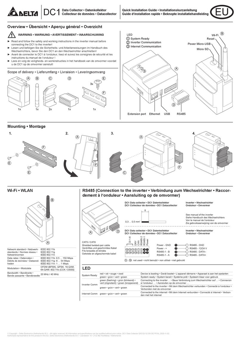
Delta PPM DC1_100 Series User manual

Delta
Delta DC1 User manual

Delta
Delta PPM DC1 100 Series Specification sheet

Delta
Delta PPM DC1 100 Series User manual

Delta
Delta DC1 User manual

Delta
Delta Data Collector PPM DC1-100 User manual

Delta
Delta DC1 User manual

Delta
Delta PPM DC1_100 Series Instruction manual

Delta
Delta DelREMO-V2.0 User manual

Delta
Delta DC1 User manual