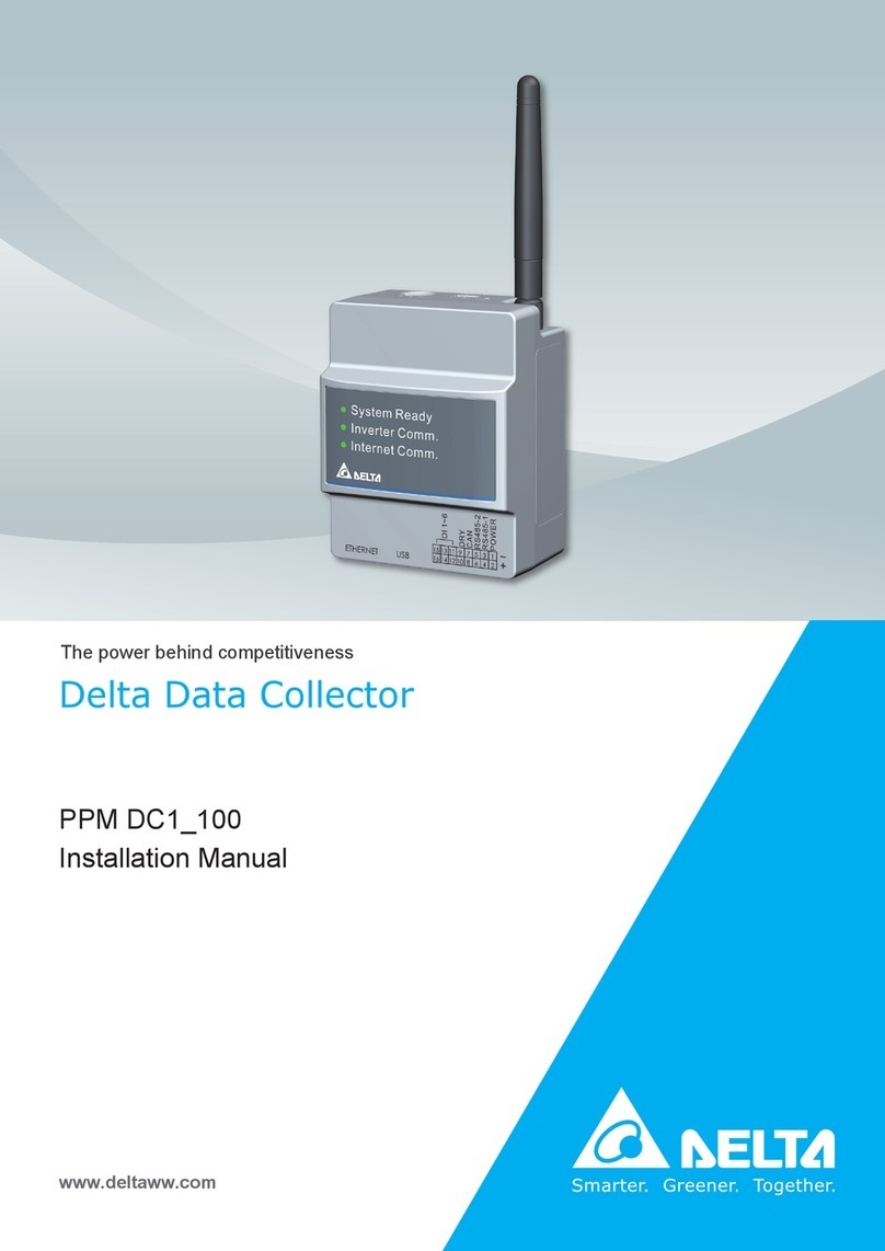
Delta PPM DC1 100 Series Specification sheet

PPM DC1_100
Operation and Installation Manual
Delta Data Collector
The power behind competitiveness
www.deltaww.com


■Introduction■
Precautions for Your Safety
Essential Points for Safety
Precautions for Use
1. Preparation before construction
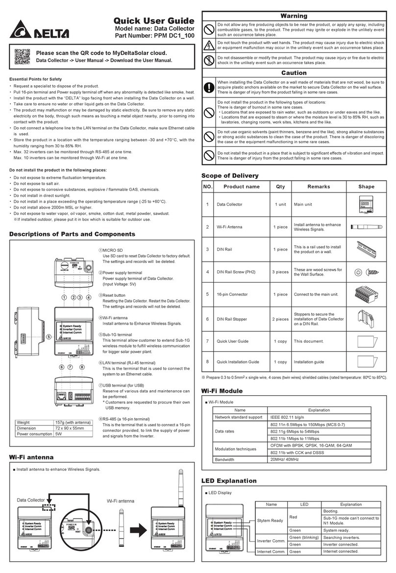
1.1.Scope of Delivery
1.2.Dimension
1.3.Descriptions and Functions of Parts and Components
2. Installation (Wired)
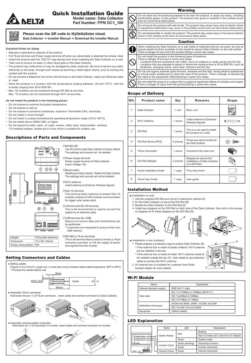
2.1.Installation on wall
2.2.Installation in box (outdoor)
2.3.Setting Connectors and Cables
2.4.RS-485 (Connection to the inverter)
3. Supported inverter models
3.1.Normal mode
3.2.Retrofit mode
4. Commissioning
4.1.First startup
4.2.Home Page (APP)
4.3.Operation Screens
4.4.Reset Method
5. DC1 mode setting process
5.1.Normal mode (RS-485)
5.2.Normal mode (Wi-Fi)
5.3.Retrofit mode (Sub_1G)
5.4.Retrofit mode
5.5.3rd party monitoring
6. Description of the page display (APP)
6.1.Energy
6.2.Infomation
6.3.History
6.4.Connection
6.5.Grid Setting
6.6.Network
6.7.FW Update
6.8.OTHER
7. Description of the page display (Cloud)
7.1.Home Page
7.2.MY SOLAR
7.3.Products
7.4.Contact Us
7.5.Edit Password
8. When Something Seems Wrong (Troubleshooting)
8.1.Error Displays
8.2.Troubleshooting
8.3.Error dialog display
9. Specifications
Appendix - N1
Appendix - N2
04
06
06
07
07
08
09
10
10
11
12
13
14
14
14
15
15
21
22
23
24
24
25
26
30
32
34
34
35
35
36
36
37
38
40
41
41
42
44
45
45
46
46
47
48
50
51
53
Contents
. . . . . . . . . . . . . . . . . . . . . . . . . . . . . . . . . . . . . . . . . . . . . . . . . . . .
. . . . . . . . . . . . . . . . . . . . . . . . . . . . . . . . . . . . . . . . . . . . . . . . . . . . . . . . . .
. . . . . . . . . . . . . . . . . . . . . . . . . . . . . . . . . . . . . . . . . . . . . . . . . . . . . .
. . . . . . . . . . . . . . . . . . . . . . . . . . . . . . . . . . . . . . . . . . . . . . . . . . . . .
. . . . . . . . . . . . . . . . . . . . . . . . . . . . . . . . . . . . . . . . . . . . . . . . . . . . . . . . .
. . . . . . . . . . . . . . . . . . . . . . . . . . . . .
. . . . . . . . . . . . . . . . . . . . . . . . . . . . . . . . . . . . . . . . . . . . . . . . . . . .
. . . . . . . . . . . . . . . . . . . . . . . . . . . . . . . . . . . . . . . . . . . . . .
. . . . . . . . . . . . . . . . . . . . . . . . . . . . . . . . . . . . . . . . . . . . . . . . . . . . . . .
. . . . . . . . . . . . . . . . . . . . . . . . . . . . . . . . . . . . . . . . . . . . . . . . . . . . . . .
. . . . . . . . . . . . . . . . . . . . . . . . . . . . . . . . . . . . . . . . . . . .
. . . . . . . . . . . . . . . . . . . . . . . . . . . . . . . . . . . . . . . . .
. . . . . . . . . . . . . . . . . . . . . . . . . . . . . . . . . . . . . . . . . . . . . . . . .
. . . . . . . . . . . . . . . . . . . . . . . . . . . . . . . . . . . . . . . . . . . . . . . . . . . . . . . . . .
. . . . . . . . . . . . . . . . . . . . . . . . . . . . . . . . . . . . . . . . . . . . . . . . . . . . . . . .
. . . . . . . . . . . . . . . . . . . . . . . . . . . . . . . . . . . . . . . . . . . . . . . . . . . .
. . . . . . . . . . . . . . . . . . . . . . . . . . . . . . . . . . . . . . . . . . . . . . . . . . . .
. . . . . . . . . . . . . . . . . . . . . . . . . . . . . . . . . . . . . . . . . . . . . . . . . . . . . . .
. . . . . . . . . . . . . . . . . . . . . . . . . . . . . . . . . . . . . . . . . . . . . . . . . . . . . . . . . . . .
. . . . . . . . . . . . . . . . . . . . . . . . . . . . . . . . . . . . . . . . . . . . . . . . . . . . . . . . . . .
. . . . . . . . . . . . . . . . . . . . . . . . . . . . . . . . . . . . . . . . . . . . . . . . . . . . . . . . .
. . . . . . . . . . . . . . . . . . . . . . . . . . . . . . . . . . . . . . . . . . . . . . . . . . . . . . . . . . .
. . . . . . . . . . . . . . . . . . . . . . . . . . . . . . . . . . . . . . . . . . . . . . . . . . . . . . . .
. . . . . . . . . . . . . . . . . . . . . . . . . . . . . . . . . . . . . . . . . . . . . . . . . . . . . . . .
. . . . . . . . . . . . . . . . . . . . . . . . . . . . . . . . . . . . . . . . . . . . . . . . . . . . . . . . . .
. . . . . . . . . . . . . . . . . . . . . . . . . . . . . . . . . . . . . . . . . . . . . . . . . . . . . . . .
. . . . . . . . . . . . . . . . . . . . . . . . . . . . . . . . . . . . . . . . . . . . . . . . . . . . . . . . . . .
. . . . . . . . . . . . . . . . . . . . . . . . . . . . . . . . . . . . . . . . . . . . .
. . . . . . . . . . . . . . . . . . . . . . . . . . . . . . . . . . . . . . . . . . . . . . . . . . . . . . . .
. . . . . . . . . . . . . . . . . . . . . . . . . . . . . . . . . . . . . . . . . . . . . . . . . . . . . . . .
. . . . . . . . . . . . . . . . . . . . . . . . . . . . . . . . . . . . . . . . . . . . . . . . . . . . . . . . . .
. . . . . . . . . . . . . . . . . . . . . . . . . . . . . . . . . . . . . . . . . . . . . . . . . . . . . . . . .
. . . . . . . . . . . . . . . . . . . . . . . . . . . . . . . . . . . . . . . . . . . . . . . . . . . . . . .
. . . . . . . . . . . . . . . . . . . . . . . . . . . . . . . . . . . . . . . . . . . .
. . . . . . . . . . . . . . . . . . . . . . . . . . . . . . . . . . . . . . . . . . . . . . . . . . . . . . .
. . . . . . . . . . . . . . . . . . . . . . . . . . . . . . . . . . . . . . . . . . . . . . . . . . . . . .
. . . . . . . . . . . . . . . . . . . . . . . . . . . . . . . . . . . . . . . . . . . . . . . . . . . .
. . . . . . . . . . . . . . . . . . . . . . . . . . . . . . . . . . . .
. . . . . . . . . . . . . . . . . . . . . . . . . . . . . . . . . . . . . . . . . . . . . . . . . . . . . . . . . . . . .
. . . . . . . . . . . . . . . . . . . . . . . . . . . . . . . . . . . . . . . . . . . . . . . . . . . . . . . . . . . . . . .
. . . . . . . . . . . . . . . . . . . . . . . . . . . . . . . . . . . . . . . . . . . . . . . . . . . . . . . . . . . . . . .
. . . . . . . . . . . . . . . . . . . . . . . . . . . . . . . . . . . . . . . . . . . . . . . . .
. . . . . . . . . . . . . . . . . . . . . . . . . . . . . . . . . . . . . . . . . . . . . . . . .
. . . . . . . . . . . . . . . . . . . . . . . . . . . . . . . . . . . . . . . . . . . . . . . . . .
. . . . . . . . . . . . . . . . . . . . . . . . . . . . . . . . . . . . . . . . . . . . . . . . . . . . . . .
. . . . . . . . . . . . . . . . . . . . . . . . . . . . . . . . . . . . . . . . . . . . . . . . . . .
. . . . . . . . . . . . . . . . . . . . . . . . . . . . . . . . . . . . . . . . . . . . . . . . . . . . .
. . . . . . . . . . . . . . . . . . . . . . . . . . . . . . . . . . . . . . . . . . . . . . . . . . . .
3
This Instruction Manual provides precautions with the following notations and symbols for safe use of the PPM DC1_100.
The expression “Product”, “Data Collector” or “DC1” refers to the PPM DC1_100. Precautions described herein contain important
aspects of safety.
Please observe and follow these descriptions.
Notations and symbols are described below:
■ Notations for safe use of the product and their meanings
Precautions for Your Safety
Failing to handle the Product properly may result in the described danger leading to slight or
intermediate level injuries and in some cases may also result in serious injury or death.
Failing to handle the Product properly may result in the described danger leading to slight or
intermediate level injuries or property damages in some instances.
■ Explanation of graphic symbols
● Electric Shock Precaution
Notifications pertaining to precautions for potential electric shock,
under specific conditions
● General
Unspecified general notifications pertaining to prohibited actions.
● Disassembly prohibited
Notifications pertaining to prohibition of equipment disassembly,
when doing so can potentially lead to injuries such as electric shock.
● General
Unspecified general notifications pertaining to instructions for users
Warning
Caution
4

When wiring the power meter, make sure to turn OFF the breakers connected to the power meter. Although small,
there is a risk of electric shock.
Do not touch the Product with wet hands.
The Product may cause injury due to electric shock or equipment malfunction may occur in the unlikely event
such an occurrence takes place.
When installing the DC1 on a wall made of materials that are not wood,
be sure to acquire plastic anchors available on the market to secure the Wall
Surface Mounting Plate on the wall surface. There is danger of injury from
the Product falling in some rare cases.
When installing the DC1, make sure to turn OFF all solar generator breakers and direct current switches for the
inverter.
Although small, there is a risk of electric shock.
Do not disassemble or modify the Product.
The Product may cause injury or fire due to electric shock in the unlikely event such an occurrence takes place.
Caution
Do not allow any fire producing objects to be near the Product, or apply any spray, including combustible gases,
to the Product. The Product may ignite or explode in the unlikely event such an occurrence takes place.
Do not install the Product in a place that is subject to significant effects of vibration
and impact. There is danger of injury from the Product falling in some rare cases.
Do not use organic solvents (paint thinners, benzene and the like), strong alkaline
substances or strong acidic substances to clean the case of the product. There is
danger of discoloring the case or the equipment malfunctioning in some rare cases.
Warning
Securely tighten the screws using a torque of 0.98 N.m.
Although small, there is a risk of burns due to defective connections.
Do not tighten the wiring using electric tools (drills), whose main purpose is to open
holes, such as impact drivers, etc.
Do not install the Product in the following types of locations:
There is danger of burnout in some rare cases.
・
Locations that are exposed to rain water, such as outdoors or under eaves and the like.
・Locations that are exposed to steam or where the moisture level is 30 to 85% RH,
such as lavatories, changing rooms, work sites, kitchens and the like.
5

Items described below must be followed as they are necessary to secure safety.
・Request a specialist to dispose of the product.
・Pull 16-pin terminal and Power supply terminal off when any abnormality is detected like smoke, heat.
・Install the product with the “DELTA” logo facing front when in stalling the Data Collector on a wall.
・Take care to ensure no water or other liquid gets on the Data Collector.
・The product may malfunction or may be damaged by static electri city. Be sure to remove any static electricity on the body,
through such means as touching a metal object nearby, prior to coming into contact with the product.
・Do not connect a telephone line to the LAN terminal on the Data Collector, make sure Ethernet cable is used.
・
Store the product in a location with the temperature ranging be tween -30 and +70°C, with the humidity ranging from 30 to 85% RH.
・Max. 32 inverters can be monitored through RS-485 at one time.
Max. 9 inverters can be monitored through Wi-Fi at one time.
Do not install the product in the following places:
・Do not expose to extreme fluctuation temperature.
・Do not expose to salt air.
・Do not expose to corrosive substances, explosive / flammable GAS, chemicals.
・Do not install in direct sunlight.
・Do not install in a place exceeding the operating temperature range (-25 to +55°C).
・Do not install above 2000m MSL or higher.
・Do not expose to water vapor, oil vapor, smoke, cotton dust, metal powder, sawdust.
※If installed outdoor, please put it in box which is suitable fo r outdoor use.
・The Product may malfunction or may be damaged by static electricity. Be sure to remove any static electricity on the body,
through such means as touching a metal object nearby, prior to coming into contact with the Product.
・
Store the Product in a location with the temperature ranging between -20 and +55°C, with the humidity ranging from 30 to 85% RH.
・The Product communicates wirelessly.
Install the Product as far away as possible from devices that emit strong radio waves, such as a civil band radio equipment.
・
The communication performance varies depending on the peripheral environment. Verify in advance that the Product is communicating
normally when installing the Data Collector on a wall.
・Avoid installing the Data Collector near iron plate or steel reinforcements and try to install the Product with as much clear space
as possible.
Essential Points for Safety
Precautions for Use
6

Verify that following items are available for use prior to using this feature.
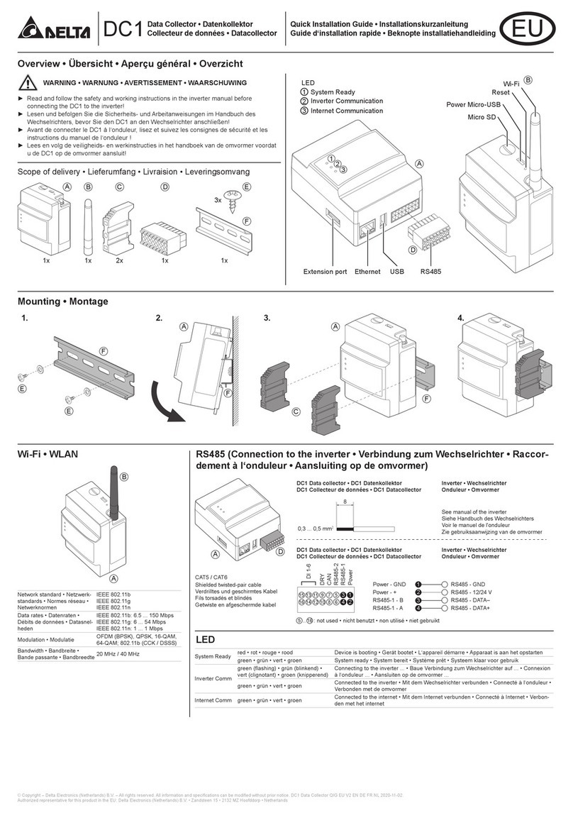
1.
Preparation before construction
1.1.Scope of Delivery
7
NO. Product name QtyRemarksShape
Data Collector
DIN Rail
DIN Rail Screw (PH2)
16-pin Connector
DIN Rail Stopper
This is a rail used to install the product on a wall.
These are wood screws for the Wall Surface.
Connect to the main unit.
1
3
4
5
6
1 unitMain unit
1 piece
Wi-Fi Antenna Install antenna to Enhance Wireless Signals.2 1 piece
3 pieces
2 pieces
1 piece
Quick Installation Guide7 1 copy Installation Guide
Stoppers to secure the installation of Data Collector
on a DIN Rail.

72mm
90 mm
170 mm
117 mm
121 mm
55 mm
unit: mm
1.2.Dimension
DC1
Din Rail
125±1
25
13.5±0.5 18 7
5.2±0.2
7.5
35
8

1.3.
Descriptions and Functions of Parts and Components
POWER IN
5V
1 423
6 87
5
①MICRO SD
Use SD card to reset Data Collector to factory default.
The settings and records will be deleted.
②Power supply terminal
Power supply terminal of Data Collector. (Input Voltage: 5V)
③Reset button
Resetting the Data Collector. Restart the Data Collector.
The settings and records will not be deleted.
④Wi-Fi antenna
Install antenna to Enhance Wireless Signals.
⑤Extend terminal
It is also possible to expand the matching Power Meter for measurement.
⑥LAN terminal (RJ-45 terminal)
This is the terminal that is used to connect the system to an
ethernet cable.
⑦USB terminal (for USB)
Reserve of various data and maintenancecan be performed.
*Customers are requested to procure their own USB memory.
⑧RS-485 (a 16-pin terminal)
This is the terminal that is used to connect a 16-pin connector
provided, to link the supply of power and signals from the Inverter.
LED Explanation
LED Explanation
Green
Green (blinking)
Green
Green
Red
Name
Internet Comm
Inverter Comm
Modulation techniques
Bandwidth
Explanation
IEEE 802.11 b/g/n
802.11n 6.5Mbps to 150Mbps (MCS 0-7)
802.11g 6Mbps to 54Mbps
802.11b 1Mbps to 11Mbps
OFDM with BPSK, QPSK, 16-QAM, 64-QAM
802.11b with CCK and DSSS
20MHz/ 40MHz
Name
Network standard support
Data rates
Wi-Fi Module
System ready.
Searching inverters.
Inverter connected.
Internet connected.
Booting.
Stytem Ready
9

2.Installation(Wired)
2.1.Installation on wall
1. DC1
(1)Use the supplied DIN Rail and mount in distribution cabinet (A).
(2)Fix the Data Collector on top of the DIN Rail.(B)
(3)Buckle the Data Collector on the DIN Rail.(C)
(4)Install two stoppers on the DIN Rail on both side of the Data Collector, then lock in the screws on stoppers to fix these stoppers
on the DIN Rail.(D)
2. DC1 + N1
(1)Use the supplied DIN Rail and mount in distribution cabinet (A).
(2)Fix the Data Collector on top of the DIN Rail.(B)
(3)Buckle the Data Collector on the DIN Rail.(C)
(4)Install two stoppers on the DIN Rail on both side of the Data Collector, then lock in the screws on stoppers to fix these stoppers
on the DIN Rail.(D)
D
C
B
A
C
B
A
D
10

2.2.Installation in box (outdoor)
1. DC1
(1)Please prepare a protective case to protect Data Collector (E).
* If the external box is made of plastic material, Wi-Fi antenna can be installed in the box.
* If the external box is made of metal, Wi-Fi antenna needs to be installed outside the box (F).
User needs to use extension cable to connect the Wi-Fi antenna.
(2)An external box is available for customer from Delta. Contact retailer for more details.
2. DC1 + N1
(1)
Please prepare a protective case to protect Data Collector and Sub-1GHz module(I)
* If the external box is made of plastic material, Wi-Fi and Sub-1G antenna can be
installed in the box
*
If the external box is made of metal, Wi-Fi and Sub-1G antenna needs to be
installed outside the Box (G&H)
(2)
An external box is available for customer from Delta. Contact retailer for more details.
E
F
I
G
H
MIN. 80mm
MIN. 200mm
MIN. 200mm
MIN. 57mm
MIN. 30mm
MIN. 95mm
MIN. 10mm
11

2.3.Setting Connectors and Cables
● Setting cables
Prepare 0.3 to 0.5mm2x single wire, 4 cores (twin wires) shielded cables (rated temperature: 80ºC to 85ºC).
* Process the cables before use.
8mm
Cable
40mm
Φ0.6~0.8 Φ5~6
● Assemble 16-pin connector
Hold down the pin ①of 16-pin connector , insert cable and connect connector to Data Collector.
● Assemble communication connector
Hold down pin ①of connector in inverter, insert cable and connect connector to inverter.
①
①
12

2.4.Connection to the inverter
8
0.3 ~ 0.5 mm2
Power
RS485-1
RS485-2
CAN
DRY
DI 1-6
1
2
35
79111315
6
810121416 4
Inverter
Shielded twisted-pair cable
CAT5 / CAT6
DC1 Data collector
RS-485
1
2
3
4
RS485 - DATA–
RS485 - DATA+
RS485 - GND
RS485 - 12/24 V
See manual of the inverter
Power - GND
Power - +
RS485-1 - B
RS485-1 - A
InverterDC1 Data collector
N2
SUB_1G
Inverter
comm. module
Red
Black
White
Green
VCC
GND
D+
D
-
■ Install SUB_1G to inverter.
■ Refer the figure and connect each wire
to the communication card of inverter.
* Screw torque required for
assembling: 1.6 N.m
13

● Connection type DC1 - inverter
Connection
type
Solivia G3
Solivia G4
RPI HxA
HXA_2XX
M6A
M8A
M10A
M15A
M20A
M30A
M50A
M70A
M88H
M125HV
...
Wired (RS485) y y y - y y y y y y y y y y
yyyyyyy
Wi-Fi - - -
---
y-------
-------
---
Mixed y y y y y y y
y y ySUB_1G -
Wired: max 32 inverters
Wi-Fi: max 9 inverters
Mixed: max 32 inverters
SUB_1G: max 25 inverters
● Connection type DC1 - Router
Ethernet or Wi-Fi
● Connection type DC1 - Smartphone
Wi-Fi
● Hints and Tipps
Connection
type
Solivia G3
Solivia G4
RPI HxA
HXA_2XX
M6A
M8A
M10A
M15A
M20A
M30A
M50A
M70A
M88H
M125HV
...
Wired (RS485) not available
Wi-Fi ---y----------
Mixed not available
Hints and Tipps
One of the connected inverters must have RS485 ID (Inverter ID) = 1
3.Supported inverter models
3.1.Normal mode
Inverter connect with DC1 via Wired (RS-485) or Wi-Fi, DC1 transfer inverter data to Delta Cloud or 3rd party monitoring device.
3.2.Retrofit mode
Converts data into SOLIVIA protocol.
14

4.Commissioning
4.1.First startup
To use Delta cloud service, user will have to register Data Collector to colud, please refer following procdeure.
MyDeltaSolar
1. This APP should collocate with Delta Inverter.
2. If inverter is not connected to cloud, you still can monitor inverter operation by APP.
Where can search for MyDeltaSolar APP?
- QR Code: Please scan the QR code to MyDeltaSolar cloud.
- IOS system: Please search “MyDeltaSolar” in App store.
- Android system: Please search “MyDeltaSolar” in Google Play.
QR Code IOS
h�ps://itunes.apple.com/ng/app/myd
eltasolar/id1271609228?mt=8
Android
h�ps://play.google.com/store/apps/de
tails?id=com.mydeltasolar_1_0_0.app
&hl=zh-TW
- Please check the smart phone is connected to the Internet and the communication is good.
ATTENTION
15

[1]
After opening the MyDeltaSolar APP, please click [Create account] to apply for
an account. (Suggestion)
If you do not apply for an account, please click the icon on the top right
to access the APP through the P2P connection.
[2]
After checking the box,
click the [OK] button.
[3]
Please fill-in basic information when register an account.
Delta has the option of providing cloud services, allowing users to have
multiple locations anytime, anywhere.
The monitoring and management of the case, all the information will be
collected and stored in the cloud reliably.
Further analysis of the anomaly and automatic notification to the user for
repair as soon as possible and replacement to avoid causing greater
power loss.
If cloud services is not required by user, please select “No”.
In this case, user may need to setup third party monitoring system.
Please find instruction in chapter 5.4.
APP is designed to connect and monitor different target devices, if there is
a Data Collector on the plant, you can directly connect to the Data Collector.
Monitor and display multiple Inverters through it.
16

[4]
Please go to the Wi-Fi settings page and connect your mobile device to Data
Collector.
[5]
SSID will be “DELTA-
serial number”.
(The serial number information is indicated
on the rating label of the machine)
The password is "DELTASOL"
[6]
After connecting to the Data Collector, please go back to the APP for connection.
Please select your connection mode. [RS-485/ Wi-Fi/ RetroFit/ Sub_1G]
(Please refer to Chapter 5 for more detailed setting process of each mode)
[RS-485] [Wi-Fi]
[RetroFit]
Product Name: Data Collector
Model: PPM DC1_100
DC Input: 12V /24V
Power Consumption: 5W
Power Micro USB Input: 5V
MADE IN CHINA
S/N:
FCC ID: 2ARTO-PPM-DC1-100
FCC Caution:
This device complies with Part 15 of the FCC Rules.
Operation is subject to the following two conditions:
(1)This device may not cause harmful interference, and
(2)this device must accept any interference received,
including interference that may cause undesired
operation.
Authorized representative
Delta Electronics (Netherlands)B.V.
Zandsteen 15, 2132 MZ Hoofddrop
The Netherlands
XXXXXXXXXXXXX
CCAM19LP0050T5
17
[Sub_1G]

Wi-Fi communication will be disconnected from your Data Collector account
at this time.
Please go back to the Wi-Fi settings page and reconnect to the Data Collector.
[7]
1. Please click [SEARCH] to detect inverter
2. Please check your inverter serial number (the serial number information is
marked on the rating label of the machine)
3. Set the inverter ID
4.
After confirming, please click the [SET] button. (please wait 2 to 10 minutes for
setting, depending on how many inverter connect to Data collector)
5.
When the message [Connected Successfully] appears, click the [NEXT] button
to proceed to the next step.
[8]
Please select proper country code for data collector to set inverter.
1
2 3
4
5
(Take Wi-Fi connection as example.)
18

[9]
[10-1]ETHERNET
Please confirm cloud register information and select correct time zone of your
region. (Cloud service will display the information base on country and time zone,
such as weather, map indicate…etc)
If select “static”, please fill in IP address for this DC1, Subnet
mask of the network, Gateway IP and DNS, then click
“SET INFO”.
1. Click “ETHERNET”
2. Protocol:
3. Click “OK” to proceed.
4. When Cloud register success shows up, means DC1 has already
connect to cloud.
5. User can start monitoring data from Delta cloud.
If select “DHCP”, APP will connected to cloud automatically.
19
1
2
3
4

[10-2]WI-FI ROUTER
20
1. Click “Scan” to find WiFi signal you
want to connect.
2. Select the proper WiFi SSID 3. Type in WiFi password and click
“Connect” to connect to the WiFi.
4. click “OK” to next step, make sure
you mobile have the internet ability.
5. Wait around 15~30 second, DC1
will connect to cloud, click OK to go
to cloud home page.
6. User can start monitoring data from
Delta cloud.
1
4
5
Other manuals for PPM DC1 100 Series
1
Table of contents
Other Delta Data Logger manuals

Delta
Delta DC1 User manual

Delta
Delta PPM DC1_100 Series User manual

Delta
Delta PPM DC1 100 Series User manual

Delta
Delta DC1 User manual

Delta
Delta DelREMO-V2.0 User manual

Delta
Delta Data Collector PPM DC1-100 User manual

Delta
Delta HD207 Series User manual

Delta
Delta DC1 User manual

Delta
Delta PPM DC1_100 Series Instruction manual

Delta
Delta DC1 User manual