manuals.online logo
Brands
  1. Home
  2. •
  3. Brands
  4. •
  5. Delta
  6. •
  7. DC Drive
  8. •
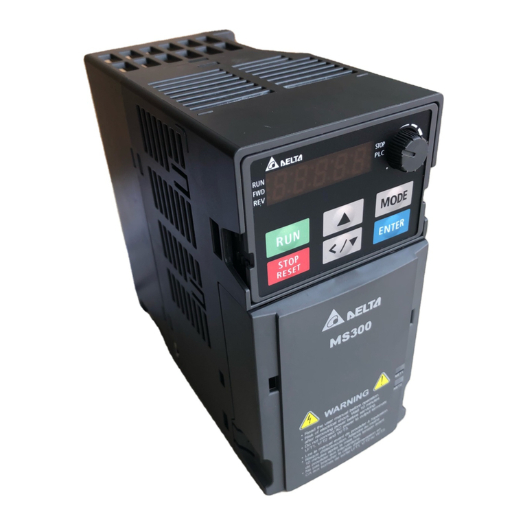
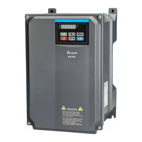
  9. Delta MH300 User manual

Delta MH300 User manual

www.deltaww.com
Digitized Automation for a Changing World
*We reserve the right to change the information in this manual without prior notice.
Industrial Automation Headquarters
Taiwan: Delta Electronics, Inc.
Taoyuan Technology Center
No.18, Xinglong Rd., Taoyuan District,
Taoyuan City 33068, Taiwan
TEL:-3-362-6301 / FAX:-3-371-6301
Asia
China: Delta Electronics (Shanghai)Co., Ltd.
No.182 Minyu Rd., Pudong Shanghai, P.R.C.

-21-6872--21-6872-
Customer Service: 400-820-
Japan: Delta Electronics (Japan), Inc.
Industrial Automation Sales Department
2-1-14 Shibadaimon, Minato-ku
-0012
-3---3--
Korea: Delta Electronics (Korea), Inc.
--gu,

-2---2--
Singapore: Delta Energy Systems (Singapore)Pte Ltd.
-
-6747--6744-
India: Delta Electronics (India)Pvt. Ltd.


-124--124-
Thailand: Delta Electronics (Thailand)PCL.
(E.P.Z),
Pattana 1 Rd., T.Phraksa, A.Muang,
Samutprakarn 10280, Thailand
--2800 / FAX66-2-2827
Australia: Delta Electronics (Australia)Pty Ltd.


Mail: IA.au@deltaww.com

Americas
USA: Delta Electronics (Americas)Ltd.

--767---767-
Brazil: Delta Electronics Brazil Ltd.


-12---12--237
Mexico: Delta Electronics International Mexico S.A. de C.V.



--3603-
EMEA
EMEA Headquarters: Delta Electronics (Netherlands)B.V.
Sales: Sales.IA.EMEA@deltaww.com
Marketing: Marketing.IA.EMEA@deltaww.com
Technical Support: iatechnicalsupport@deltaww.com
Customer Support: Customer-Support@deltaww.com
Service: Service.IA.emea@deltaww.com
(0)
BENELUX: Delta Electronics (Netherlands)B.V.
Automotive Campus 260,

(0)
DACH: Delta Electronics (Netherlands)B.V.
-

(0)
France: Delta Electronics (France)S.A.


Mail: Sales.IA.FR@deltaww.com
(0)
Iberia: Delta Electronics Solutions (Spain)S.L.U


(0)

Mail: Sales.IA.Iberia@deltaww.com
Italy: Delta Electronics (Italy)S.r.l.
(CO)

Mail: Sales.IA.Italy@deltaww.com

Russia: Delta Energy System LLC


Mail: Sales.IA.RU@deltaww.com

Turkey: Delta Greentech Elektronik San. Ltd. Sti. (Turkey)
-A

Mail: Sales.IA.Turkey@deltaww.com

MEA: Eltek Dubai (Eltek MEA DMCC)

Jumeirah Lakes Towers, Dubai, UAE
Mail: Sales.IA.MEA@deltaww.com
(0)
Delta High Performance Compact Drive - MH300 Series User Manual
Delta High Performance Compact Drive
MH300 Series User Manual
DELTA_IA-MDS_MS300_UM_EN_20221122
I
Copyright notice
©Delta Electronics, Inc. All rights reserved.
All information contained in this user manual is the exclusive property of Delta Electronics Inc.
(hereinafter referred to as "Delta ") and is protected by copyright law and all other laws. Delta retains the
exclusive rights of this user manual in accordance with the copyright law and all other laws. No parts in
this manual may be reproduced, transmitted, transcribed, translated or used in any other ways without
the prior consent of Delta.
Limitation of Liability
The contents of this user manual are only for the use of the AC motor drives manufactured by Delta. Except
as defined in special mandatory laws, Delta provides this user manual “as is” and does not offer any kind
of warranty through this user manual for using the product, either express or implied, including but not
limited to the following: (i) this product will meet your needs or expectations; (ii) the information contained
in the product is current and correct; (iii) the product does not infringe any rights of any other person. You
shall bear your own risk to use this product.
In no event shall Delta, its subsidiaries, affiliates, managers, employees, agents, partners and licensors
be liable for any direct, indirect, incidental, special, derivative or consequential damages (including but not
limited to the damages for loss of profits, goodwill, use or other intangible losses) unless the laws contains
special mandatory provisions to the contrary.
Delta reserves the right to make changes to the user manual and the products described in the user
manual without prior notice and afterwards.
II
PLEASE READ PRIOR TO INSTALLATION FOR SAFETY.
 Disconnect AC input power before connecting any wiring to the AC motor drive.
 Even if the power has been turned off, a charge may still remain in the DC-link
capacitors with hazardous voltages before the POWER LED is OFF. Do not touch
the internal circuits and components.
 There are highly sensitive MOS components on the printed circuit boards.
These components are especially sensitive to static electricity. Take anti-static
measures before touching these components or the circuit boards.
 Never modify the internal components or wiring.
 Ground the AC motor drive by using the ground terminal. The grounding method
must comply with the laws of the country where the AC motor drive is to be
installed.
 DO NOT install the AC motor drive in a location
with high temperature, direct
sunlight or inflammable materials or gases.
 Never connect the AC motor drive output terminals U/T1, V/T2 and W/T3 directly
to the AC mains circuit power supply.
 After finishing the wiring of the AC motor drive, check if U/T1, V/T2 and W/T3 are
short-circuited to ground with a multimeter. Do NOT power the drive if short circuits
occur. Eliminate the short circuits before the drive is powered.
 The rated voltage of power system to install motor drives is listed below. Ensure
that the installation voltage is in the correct range when installing a motor drive.
For 115V models, the range is between 85–132 V.
For 230V models, the range is between 170–264 V.
For 460V models, the range is between 323–528 V.
 Refer to the table below for short circuit rating:
Model (Power) Short circuit rating
115V 5 kA
230V 5 kA
460V 5 kA

Only qualified persons are allowed to install, wire and maintain the AC motor
drives.
 Even if the three-phase AC motor is stopped, a charge with hazardous voltages
may still remain in the main circuit terminals of the AC motor drive.
 The performance of electrolytic capacitor will degrade if it is not charged for a long
time. It is recommended to charge the drive which is stored in no charge condition
every 2 years for 3~4 hours to restore the performance of electrolytic capacitor in the
motor drive. Note: When power up the motor drive, use adjustable AC power source
(ex. AC autotransformer) to charge the drive at 70%~80% of rated voltage for 30
minutes (do not run the motor drive). Then charge the drive at 100% of rated voltage
for an hour (do not run the motor drive). By doing these, restore the performance of
electrolytic capacitor before starting to run the motor drive. Do NOT run the motor drive
at 100% rated voltage right away.
III

Pay attention to the following precautions when transporting and installing this
package (including wooden crate and wood stave)
1 If you need to deworm the wooden crate, do not use fumigation or you will
damage the drive. Any damage to the drive caused by using fumigation
voids the warranty.
2 Use other methods, such as heat treatment or any other non-fumigation
treatment, to deworm the wood packaging material.
3 If you use heat treatment to deworm, leave the packaging materials in an
environment of over 56°C for a minimum of thirty minutes.
Connect the drive to a three-phase three-wire or three-phase four-
wire Wye
system to comply with UL standards.
If the motor drive produces a leakage current of over AC 3.5mA or over DC 10mA
on the Protective Earthing conductor, the minimum specifications required of the
Protective Earthing conductor to be installed have to comply with the national, local
laws and regulations or follow IEC61800-5-1 to do grounding.
MH300 series is designed for the applic
ation of general industrial environment.
Non-linear load causes harmonic current, if the drive uses with public low voltage
(e.g. the power supplies to houses), then you have to assemble an appropriate
restraint equipment (e.g. isolation transformer or inp
ut reactor) to restrain the
interference may be caused. Contact with Delta for more information.
NOTE:
In the pictures in this manual, the cover or safety shield is disassembled only when explaining the
details of the product. During operation, install the top cover and wiring correctly according to the
provisions. Refer to the operation descriptions in the manual to ensure safety.
The figures in this instruction are only for reference and may be slightly different depending on your
model, but it will not affect your customer rights.
The content of this manual may be revised without prior notice. Consult our distributors or download
the latest version at http://www.deltaww.com/iadownload_acmotordrive.
IV
Table of Contents
CHAPTER 1 INTRODUCTION ................................................................................................. 1-1
1-1 Nameplate Information…..............................................................................................1-2
1-2 Model Name..................................................................................................................1-3
1-3 Serial Number...............................................................................................................1-3
1-4 Apply After Service by Mobile Device...........................................................................1-4
1-5 RFI Jumper...................................................................................................................1-5
CHAPTER 2 DIMENSIONS.. …………………………………………………………………………2-1
2-1 Frame A………………………………………………………………………………………2-2
2-2 Frame B………………………………………………………………………………………2-3
2-3 Frame C………………………………………………………………………………………2-4
2-4 Frame D………………………………………………………………………………………2-5
2-5 Frame E………………………………………………………………………………………2-6
2-6 Frame F………………………………………………………………………………………2-7
2-7 Frame G.......................................................................................................................2-8
2-8 Frame H.......................................................................................................................2-9
2-9 Frame I...................................................................................................................2-10
2-10 Digital Keypad……......………………………………………………………………2-11
CHAPTER 3 INSTALLATION................................................................................................... 3-1
3-1 Mounting Clearance.....................................................................................................3-2
3-2 Airflow and Power Dissipation......................................................................................3-3
CHAPTER 4 WIRING ............................................................................................................... 4-1
4-1 System Wiring Diagram...............................................................................................4-3
4-2 Wiring ..........................................................................................................................4-4
CHAPTER 5 MAIN CIRCUIT TERMINALS ............................................................................ 5-1
5-1 Main Circuit Diagram...................................................................................................5-4
5-2 Main Circuit Terminals..................................................................................................5-5
CHAPTER 6 CONTROL TERMINALS..................................................................................... 6-1
6-1 Control Terminal Specifications...................................................................................6-4
CHAPTER 7 OPTIONAL ACCESSORIES ............................................................................... 7-1
7-1 All Brake Resistors and Brake Units Used in AC Motor Drives...................................7-2
7-2 Magnetic Contactor / Air Circuit Breaker and Non-Fuse Circuit Breaker………7-6
7-3 Fuse Specification Chart ..........................................................................................7-10
7-4 AC / DC Reactors......................................................................................................7-13
V
7-5 Zero Phase Reactors................................................................................................7-43
7-6 EMC Filter.................................................................................................................7-46
7-7 EMC Shield Plate......................................................................................................7-54
7-8 Capacitive Filter.........................................................................................................7-59
7-9 The Assembly of NEMA Kit.......................................................................................7-61
7-10 The Assembly of Fan Kit..........................................................................................7-74
7-11 Keypad Panel Mounting ……..................................................................................7-78
7-12 DIN-Rail Mounting...................................................................................................7-79
7-13 Mounting Adapter Plate…………………………………….……………………………7-81
7-14 Digital Keypad – KPC-CC01…………………………………………………………….7-85
CHAPTER 8 OPTION CARDS...................................................................................................8-1
8-1 Option Card Installation...............................................................................................8-2
8-2 EMM-PG01L -- PG Card (Line Driver) .............................................................................8-13
8-3 EMM-PG01O -- PG Card (Open Collector) .......................................................................8-16
8-4 EMM-PG01R -- PG Card (Resolver/Encoder Signal Input) ...................................................8-19
8-5 EMM-D33A -- Three-point Digital Input/Three-point Digital Output Extension ..........................8-22
8-6 EMM-A22A -- Two Sets of Analog Input/Two Sets of Analog Output Extension ........................8-23
8-7 EMM-R2CA -- Relay Output Extension (Three-point N.C. Output Terminal) .............................8-24
8-8 EMM-R3AA -- Relay Output Extension (Three-point N.O. Output Terminal) .............................8-25
8-9 EMM-BPS02 -- +24V Power Extension Card ...................................................................8-26
8-10 CMM-DN02 -- Communication Extension Card, DeviceNet ...............................................8-28
8-11 CMM-EIP02 -- Communication Extension Card, EtherNet/IP .............................................8-31
8-12 CMM-EIP03 -- Communication Extension Card, EtherNet/IP .............................................8-35
8-13 CMM-PD02 -- Communication Extension Card, PROFIBUS DP .........................................8-39
8-14 CMM-EC02 -- Communication Extension Card, EtherCAT.................................................8-41
8-15 Delta Standard Fieldbus Cables……………………….……………………................8-44
CHAPTER 9 SPECIFICATION..................................................................................................9-1
9-1 115V Models…………………………….........................................................................9-2
9-2 230V Models……………………………......................................................................9-3
9-3 460V Models……………………………......................................................................9-6
9-4 General Specifications……………………………………………………………………..9-8
9-5 Environment for Operation, Storage and Transportation…………………….................9-9
9-6 Derating Curve………………………………………………………...............................9-10
CHAPTER 10 DIGITAL KEYPAD ...........................................................................................10-1
10-1 KPMH-LC01 Keypad…………………………………………......................................10-2
10-2 Descriptions of Keypad Functions………………………………………………………10-2
10-3 Keypad Operation Process………………………………………………………………10-3
10-4 Reference Table for the 16-segment Digital Keypad LED Display…………………..10-9
VI
CHAPTER 11 SUMMARY OFPARAMETERS SETTINGS.................................................... 11-1
CHAPTER 12 DESCRIPTIONS OFPARAMETER SETTINGS ..................................... 12.1-00-1
12-1 Descriptions of Parameter Settings………………………………………………12.1-00-1
00 Drive Parameters………………………………………………………………12.1-00-2
01 Basic Parameters………………………………………………………………12.1-01-1
02 Digital Input / Output Parameters……………………………………………12.1-02-1
03 Analog Input / Output Parameters……………………………………………12.1-03-1
04 Multi-Stage Speed Parameters………………………………………………12.1-04-1
05 Motor Parameters………………………………………………………………12.1-05-1
06 Protection Parameters (1) ……………………………………………………12.1-06-1
07 Special Parameters……………………………………………………………12.1-07-1
08 High-function PID Parameters………………………………………………12.1-08-1
09 Communication Parameters…………………………………………………12.1-09-1
10 Speed Feedback Control Parameters………………………………………12.1-10-1
11 Advanced Parameters…………………………………………………………12.1-11-1
12 Tension Control Parameters…………………………………………………12.1-12-1
13 Macro (User-defined) ……..…………………………………………………12.1-13-1
14 Protection Parameters (2) ………...............................................................12.1-14-1
12-2 Adjustment & Applications……………………………………………………………12.2-1
CHAPTER 13 WARNING CODES ......................................................................................... 13-1
CHAPTER 14 FAULTCODES ............................................................................................... 14-1
CHAPTER 15 CANopen OVERVIEW.................................................................................... 15-1
15-1 CANopen Ovreview.................................................................................................15-3
15-2 Wiring for CANopen.................................................................................................15-7
15-3 CANopen Communication Interface Descriptions....................................................15-8
15-4 CANopen Supporting Index...................................................................................15-20
15-5 CANopen Fault Codes...........................................................................................15-28
15-6 CANopen LED Function.........................................................................................15-33
CHAPTER 16 PLC FUNCTION APPLICATIONS................................................................... 16-1
16-1 PLC Summary..........................................................................................................16-2
16-2 Notes Before PLC Use.............................................................................................16-3
16-3 Turn On....................................................................................................................16-5
16-4 Basic Principles of PLC Ladder Diagrams.............................................................16-16
16-5 Various PLC Device Functions...............................................................................16-28
16-6 Introduction to the Command Window...................................................................16-40
16-7 Display and Treatment of PLC Related Faults and Codes...................................16-114
16-8 Explanation of each PLC Mode Control (Speed, Torque) ....................................16-115
16-9 Count Function Using Pulse Input........................................................................16-118
VII
16-10 CANopen Master Control Applications....................................................................16-119
16-11 Modbus Remote IO Control Applications (Use MODRW) ..........................................16-130
CHAPTER 17SAFETORQUE OFF FUNCTION………………………......…………………….17-1
17-1 Basic Function Description…………........................................................................17-2
17-2 Safe Torque Off Terminal Function Description........................................................17-3
17-3 Wiring Diagram........................................................................................................17-4
17-4 Failure Rate of the Drive Safety Function................................................................17-5
17-5 Reset the Parameter Settings…..............................................................................17-5
17-6 Timing Diagram Description......................................................................................17-6
17-7 Fault Codes and Troubleshooting Instructions……...…………………………………17-9
17-8 Test and Fault Confirmation…………………………...………………………………….17-11
APPENDIX A. MODBUS PROTOCOL…………………………………..………………………..A-1
A-1 Code Description…………............................................................................................A-2
A-2
Data Format..................................................................................................................A-2
A-3 Communication Protocol...............................................................................................A-4
A-4 Address List..................................................................................................................A-9
A-5 Exception Response…................................................................................................A-16
APPENDIX B. REVISION HISTORY……………………………………..………………………..B-1
Issued Edition: 01
Firmware Version: V1.04 (Refer to Parameter 00-06 on the product to get the firmware version.)
Issued Date: 2023/2
VIII
[This page intentionally left blank]
Chapter 1 IntroductionMH300
1-1
Chapter 1 Introduction
1-1 Nameplate Information
1-2 Model Name
1-3 Serial Number
1-4 Apply After Service by Mobile Device
1-5 RFI Jumper
Chapter 1 IntroductionMH300
1-2
After receiving the AC motor drive, check for the following. Inspect the unit after unpacking to ensure
that it was not damaged during shipment. Make sure that the part number printed on the package matches
the part number indicated on the nameplate.
1. Make sure that the mains voltage is within the range indicated on the nameplate. Install the AC motor
drive according to the instructions in this manual.
2. Before applying power, make sure that all devices, including mains power, motor, control board, and
digital keypad are connected correctly.
3. When wiring the AC motor drive, make sure that the wiring for the input terminals “R/L1, S/L2, T/L3”,
and the output terminals "U/T1, V/T2, W/T3” are correct to prevent damage to the drive.
4.
When power is applied, use the digital keypad (KPMH-LC01) to select the language and set
parameters. When executing a trial run, begin with a low speed and then gradually increase the speed
to the desired speed.
1-1 Nameplate Information
Chapter 1 IntroductionMH300
1-3
1-2 Model Name
1-3 Serial Number
Chapter 1 IntroductionMH300
1-4
1-4 Apply After Service by Mobile Device
1-4-1 Location of Service Link Label
Frame A, B
Service link label (Service Label) will be pasted
on the keypad area on the case body,
as below
drawing shown.
Frame C–I
Service link label (Service Label) will be pasted on
the area as below drawing shown.
1-4-2 Service Link Label
Scan QR Code to apply
1. Find out the QR code sticker (as above shown).
2. Use a Smartphone to run a QR Code reader APP.
3. Point your camera to the QR Code. Hold your camera steady so that the QR code comes into focus.
4. Access the Delta After Service website.
5. Fill your information into the column marked with an orange star.
6. Enter the CAPTCHA and click “Submit” to complete the application.
Cannot find out the QR Code?
1. Open a web browser on your computer or smart phone.
2. Key in https://service.deltaww.com/ia/repair in address bar and press enter.
3. Fill your information into the columns marked with an orange star.
4. Enter the CAPTCHA and click “Submit” to complete the application.
Chapter 1 IntroductionMH300
1-5
1-5 RFI Jumper
The drive contains Varistors / MOVs that are connected from phase to phase and from phase to ground to
protect the drive against mains surges or voltage spikes.
Because the Varistors / MOVs from phase to ground are connected to ground with the RFI jumper,
removing the RFI jumper disables the protection.
(1) In models with a built-in EMC filter, the RFI jumper connects the filter capacitors to ground to form a
return path for high frequency noise in order to isolate the noise from contaminating the mains power.
Removing the RFI jumper strongly reduces the effect of the built-in EMC filter.
(2) Although a single drive complies with the international standards for leakage current, an installation
with several drives with built-in EMC filters can trigger the RCD. Removing the RFI jumper can help,
but the EMC performance of each drive is no longer guaranteed.
Non-built-in EMC filter models
Frame A–I
Loosen the screw and remove the RFI jumper (as shown below). Fasten the screw again after you remove
the RFI jumper.
Screw Torque: 4–6 kg-cm / (3.5–5.2 lb-in.) / (0.39–0.59 Nm)
Chapter 1 IntroductionMH300
1-6
Built-in EMC filter models
Frame B–F
Remove the RFI jumper with a screwdriver (as shown below).
Frame G
Remove the RFI jumper with a screwdriver (as shown below).


Chapter 1 IntroductionMH300
1-7
Frame H–I
1. Remove RFI ON (frame H) or the screw of RFI-1 ON (frame I)
Screw Torque: 6–8 kg-cm / (5.2–6.9 lb-in.) / (0.59–0.78 Nm)
2. Remove the RFI jumper RFI-2 (frame I).
Chapter 1 IntroductionMH300
1-8
Isolating main power from ground:
When the power distribution system of the drive is a floating ground system (IT Systems) or an
asymmetric ground system (Corner Grounded TN Systems), you must remove the RFI jumper. Removing
the RFI jumper disconnects the internal capacitors from ground to avoid damaging the internal circuits and
to reduce the ground leakage current.
Important points regarding ground connection:
 To ensure the safety of personnel, proper operation, and to reduce electromagnetic radiation, you must
properly ground the drive during installation.
 The diameter of the cables must comply with the local safety regulations.
 The shields of shielded cables must be connected to the ground of the drive to meet safety regulations.
 The shields of shielded power cables can only be used as the ground for equipment when the above
points are met.
 When installing more drives, do not connect ground terminals of each drive to the ground with single
point and series connection, but connects with single point and parallel connection. See the following
pictures.
Pay particular attention to the following points:
 Do not remove the RFI jumper while the power is on.
 Removing the RFI jumper also disconnects the built-in EMC filter capacitors. Compliance with the EMC
specifications is no longer guaranteed.
 Do not remove the RFI jumper if the mains power is a symmetrical grounded power system in order to
maintain the efficiency for EMC circuit.
 Do not remove the RFI jumper while conducting high voltage tests. When conducting a high voltage
test to the entire facility, you must disconnect the mains power and the motor if the leakage current is
too high.
Floating Ground System (IT Systems)
A floating ground system is also called an IT system, an ungrounded system, or a high impedance /
resistance (greater than 30 Ω) grounded system.
 Disconnect the RFI jumper.
 Check whether there is excess electromagnetic radiation affecting nearby low-voltage circuits.
 In some situations, the transformer and cable naturally provide enough suppression. If in doubt, install
an extra electrostatic shielded cable on the power supply side between the main circuit and the control
terminals to increase suppression.
Chapter 1 IntroductionMH300
1-9
 Do not install an external EMC filter. The EMC filter is connected to ground through the filter capacitors,
thus connecting the power input to ground. This is very dangerous and can easily damage the drive.
Asymmetric Ground System (Corner Grounded TN Systems)
Caution: Do not remove the RFI jumper while there is power to the input terminal of the drive.
In the following four situations, you must remove the RFI jumper. This is to prevent the system from
grounding through the RFI and filter capacitors and damaging the drive.
You must remove the RFI jumper
1. Grounding at a corner in a triangle configuration
L2
L3
L1
2. Grounding at a midpoint in a polygonal
configuration
L2
L3
L1
3. Grounding at one end in a single-phase
configuration
L1
N
4. No stable neutral grounding in a three-phase
autotransformer configuration
L1
L2
L3
L1
L2
L3
You can use the RFI jumper
Internal grounding through RFI capacitors, which reduces
electromagnetic radiation. In a symmetrically grounding
power system with higher EMC requirements, you can
install an EMC filter. As a reference, the diagram on the
right is a symmetrical grounding power system.
L2
L
3
L
1
Chapter 1 IntroductionMH300
1-10
[This page intentionally left blank]
Chapter 2 DimensionsMH300
2-1
Chapter 2 Dimensions
2-1 Frame A
2-2 Frame B
2-3 Frame C
2-4 Frame D
2-5 Frame E
2-6 Frame F
2-7 Frame G
2-8 Frame H
2-9 Frame I
2-10 Digital Keypad

This manual suits for next models

92

Other Delta DC Drive manuals

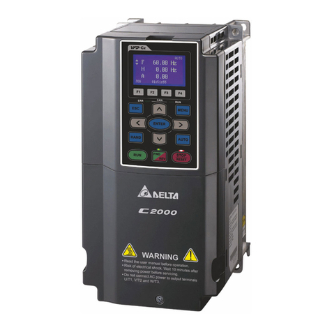
Delta C2000 Series User manual

Delta

Delta C2000 Series User manual

Delta VFD-EL-W Series User manual

Delta

Delta VFD-EL-W Series User manual

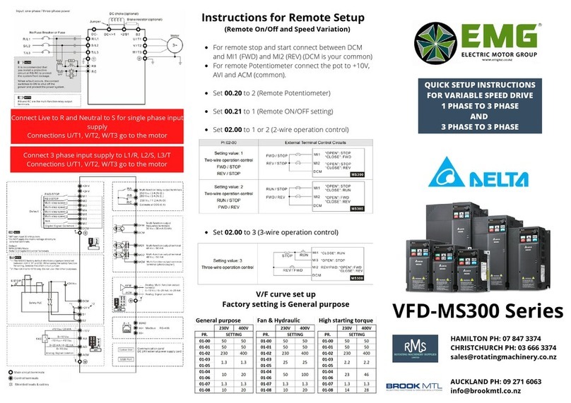
Delta VFD-MS300 Series Manual

Delta

Delta VFD-MS300 Series Manual

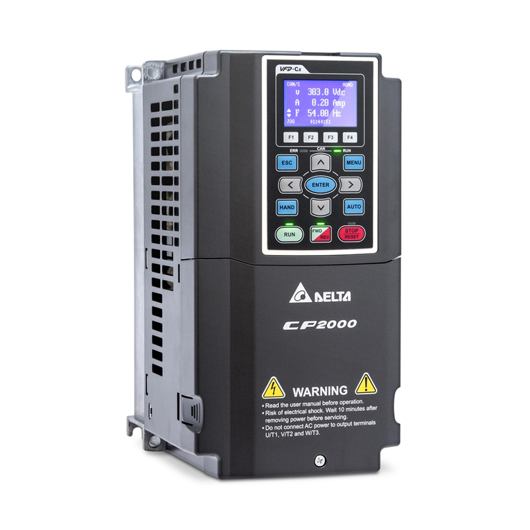
Delta CP2000 Series User manual

Delta

Delta CP2000 Series User manual

Delta CP2000 Series User manual

Delta

Delta CP2000 Series User manual

Delta VFD-E User manual

Delta

Delta VFD-E User manual

Delta C2000 Plus Series User manual

Delta

Delta C2000 Plus Series User manual

Delta VFD-L-I Series User manual

Delta

Delta VFD-L-I Series User manual

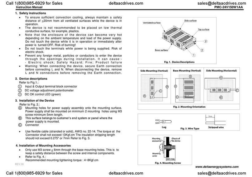
Delta PMC-24V150W1AA User manual

Delta

Delta PMC-24V150W1AA User manual

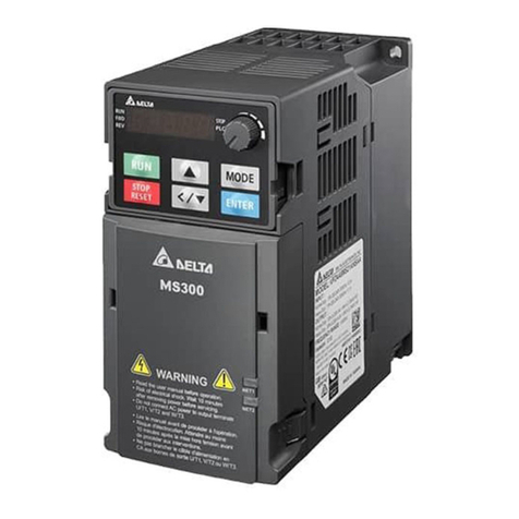
Delta MS300 Series User manual

Delta

Delta MS300 Series User manual

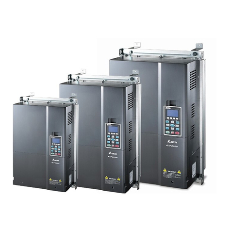
Delta CT2000 Series User manual

Delta

Delta CT2000 Series User manual

Delta VFD-ME300 Series Manual

Delta

Delta VFD-ME300 Series Manual

Delta VFD-EL-C Series User manual

Delta

Delta VFD-EL-C Series User manual

Delta VFD-A User manual

Delta

Delta VFD-A User manual

Delta IED-S Series User manual

Delta

Delta IED-S Series User manual

Delta ME300 Series User manual

Delta

Delta ME300 Series User manual

Delta VFD-B User manual

Delta

Delta VFD-B User manual

Delta VFD-EL-W Series User manual

Delta

Delta VFD-EL-W Series User manual

Delta VFD-B 230V Series User manual

Delta

Delta VFD-B 230V Series User manual

Delta VFD-A Series User manual

Delta

Delta VFD-A Series User manual

Delta VFD-BW Series User manual

Delta

Delta VFD-BW Series User manual

Delta CFP2000 Series User manual

Delta

Delta CFP2000 Series User manual

Delta MS300 Series User manual

Delta

Delta MS300 Series User manual

Delta VFD-ED Series User manual

Delta

Delta VFD-ED Series User manual

Popular DC Drive manuals by other brands

halstrup-walcher PSD4 Series instruction manual

halstrup-walcher

halstrup-walcher PSD4 Series instruction manual

Festo ESBF-BS-32 Instructions and Operating

Festo

Festo ESBF-BS-32 Instructions and Operating

Sprint Electric 340 product manual

Sprint Electric

Sprint Electric 340 product manual

elero RolMotion/D+ M Series Operating and assembly instructions

elero

elero RolMotion/D+ M Series Operating and assembly instructions

YASKAWA JOHB-SMP3-MA Technical manual

YASKAWA

YASKAWA JOHB-SMP3-MA Technical manual

Faulhaber MC 5010 Communications manual

Faulhaber

Faulhaber MC 5010 Communications manual

ABB ACQ550-x1-06A6-2 user manual

ABB

ABB ACQ550-x1-06A6-2 user manual

LiFud LF-GSD150YV024A quick start guide

LiFud

LiFud LF-GSD150YV024A quick start guide

Bosch Rexroth MOBILEX GFT-W 30 Series operating instructions

Bosch

Bosch Rexroth MOBILEX GFT-W 30 Series operating instructions

Simu T5 AUTOSHORT BHz Original instructions

Simu

Simu T5 AUTOSHORT BHz Original instructions

StepperOnline BLD-550S user manual

StepperOnline

StepperOnline BLD-550S user manual

Oerlikon Fairfield Torque-Hub S40B Series Service manual

Oerlikon

Oerlikon Fairfield Torque-Hub S40B Series Service manual

PR electronics 5203B manual

PR electronics

PR electronics 5203B manual

Mitsubishi Electric FR-D700 Series instruction manual

Mitsubishi Electric

Mitsubishi Electric FR-D700 Series instruction manual

ABB ACS580-01 Series Quick installation and start-up guide

ABB

ABB ACS580-01 Series Quick installation and start-up guide

Rockwell Automation Allen-Bradley IMPACT 1336 Series troubleshooting manual

Rockwell Automation

Rockwell Automation Allen-Bradley IMPACT 1336 Series troubleshooting manual

Aerotech Ndrive FCL Hardware manual

Aerotech

Aerotech Ndrive FCL Hardware manual

Inovance MD500 Series user guide

Inovance

Inovance MD500 Series user guide

manuals.online logo
manuals.online logoBrands
  • About & Mission
  • Contact us
  • Privacy Policy
  • Terms and Conditions

Copyright 2025 Manuals.Online. All Rights Reserved.