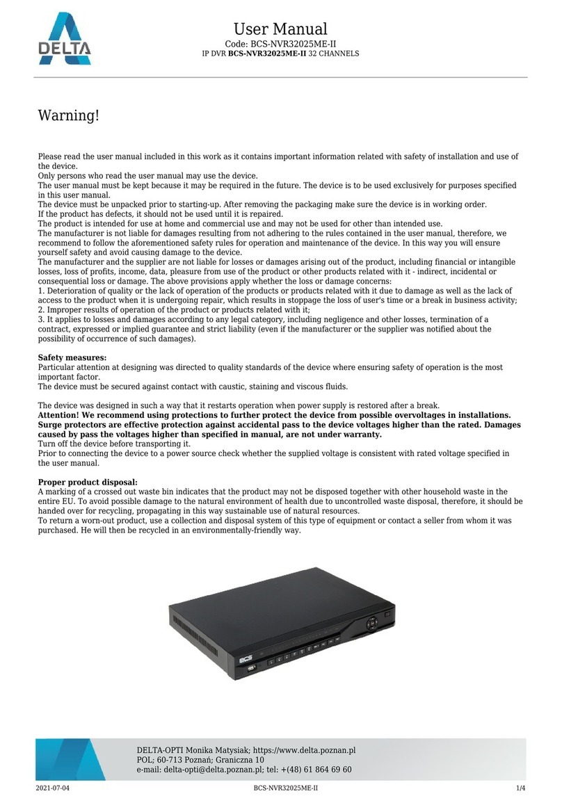
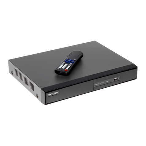
Delta VIVOTEK ND9326P User manual

2 - User's Manual
Table of Contents
Chapter One Hardware Installation and Initial Configuration .......................................................................... 8
Introducing the Network Video Recorder ............................................................................................................... 8
Special Features ............................................................................................................................................. 8
Safety ............................................................................................................................................................ 11
Chassis Dimensions .................................................................................................................................. 12
Physical Description ........................................................................................................................................... 12
LED Indicators...................................................................................................................................................... 32
Power Up and Power Down ................................................................................................................................. 33
Configuring Crowd Control Solution ..................................................................................................................... 34
Section One Management over a Local Console ..................................................................................................... 46
Chapter Two Introduction to the Local Console Interface................................................................................ 46
2-1. How to Begin.......................................................................................................................................... 48
2-2. Operation on Camera View Cell............................................................................................................. 54
2-2-1. PTZ Panel........................................................................................................................................... 54
2-2-2. Digital zoom Panel.............................................................................................................................. 57
2-2-3. Play Recording Clips Panel ................................................................................................................ 58
2-2-4. DI/DO.................................................................................................................................................. 59
2-2-5. Others ................................................................................................................................................. 59
2-2-6. Right-click Commands........................................................................................................................ 60
Chapter Three Configuation Using the Local Console......................................................................................... 61
The Main Control Portal ....................................................................................................................................... 61
3-1. Layout .................................................................................................................................................... 61
3-2. DI/DO ..................................................................................................................................................... 61
3-3. Search recording clips ........................................................................................................................... 62
3-3-1. Basic Search................................................................................................................................62
3-3-2. Alarm Search ............................................................................................................................... 66
3-3-3. POS Search................................................................................................................................. 70
3-3-5. Smart VCA event search ............................................................................................................. 73
3-3-6. Storyboard ................................................................................................................................... 81
3-4. Export recordings................................................................................................................................... 85
3-5. Settings .................................................................................................................................................. 87
3-5-1. Settings - Overview...................................................................................................................... 87
3-5-2. Settings–Camera–Management .................................................................................................. 88
3-5-4. Settings–Camera–Recording....................................................................................................... 96
3-5-5. Settings–Camera–Media ............................................................................................................. 99
3-5-6. Settings - Camera - Image......................................................................................................... 106
3-5-7. Settings–Camera–Smart VCA Detection....................................................................................111
3-5-8. Settings–Camera–Motion Detection.......................................................................................... 112
3-5-9. Settings - Camera - PTZ settings .............................................................................................. 113
3-5-10. Settings - Camera - Port forwarding ........................................................................................ 115
User's Manual - 3
3-5-11. Settings - Camera - Update firmware ......................................................................................116
3-5-12. Settings–Alarm–Alarm.............................................................................................................118
3-5-13. Settings - Alarm - Email .......................................................................................................... 131
3-5-14. Settings–System–Information................................................................................................. 132
3-5-15. Settings–System–Maintenance .............................................................................................. 133
3-5-16. Settings - System - Display..................................................................................................... 134
3-5-17. Settings - System - PoE management.................................................................................... 135
3-5-18. Settings - System - UPS......................................................................................................... 137
3-5-19. Settings - System - Log .......................................................................................................... 138
3-5-20. Settings - System - VIVOCloud service.................................................................................. 140
3-5-21. Settings – System - Customer support................................................................................... 141
3-5-22. Settings–User ......................................................................................................................... 142
3-5-23. Settings–User-Login / Logout ................................................................................................. 144
3-5-24. Settings–Storage .................................................................................................................... 145
Storage Volume RAID Levels..................................................................................................................... 147
3-5-25. Settings - Storage - Scheduled backup .................................................................................. 152
3-5-26. Settings - Network .................................................................................................................. 155
Settings - Network - IP ........................................................................................................................ 155
Settings - DDNS.................................................................................................................................. 156
Settings–Service ................................................................................................................................. 157
Settings–HTTPS certificate................................................................................................................. 161
3-6. POS .................................................................................................................................................... 162
3-7. Trend Micro IoT Security Service ........................................................................................................ 164
3-8. Information .......................................................................................................................................... 165
Section Two Management over a Web Console...................................................................................................... 166
Chapter Four Login and Getting Started ........................................................................................................... 167
4-1. Login .......................................................................................................................................................... 167
4-2. Graphical Layout and Screen Elements - Liveview.................................................................................... 171
4-2-1. Device List Panel ............................................................................................................................. 172
4-2-2. Layout .............................................................................................................................................. 175
4-2-3. Scene............................................................................................................................................... 176
4-2-5. View Cell panel ................................................................................................................................ 177
Adding Cameras to View Cells................................................................................................................... 177
4-3. Graphical Layout and Screen Elements - Playback................................................................................... 184
Playback Panel ......................................................................................................................................... 185
4-4. Graphical Layout and Screen Elements - Search ...................................................................................... 187
Chapter Five System Settings ............................................................................................................................. 189
Safety and Compatibility .................................................................................................................................... 191

4 - User's Manual
The NVR also supports the VIVOCloud Retail app. Please refer to the VIVOCloud Retail app
User Guide for details.
IMPORTANT:
セキュリティ基準(新規則第34条の10)
「本製品は 電気通信事業者(移動通信会社、固定通信会社、インターネットプロバイダ等)
の通信回線(公衆無線 LAN を含む )
に直接接続することができません。本製品をインターネットに接続する場合は、必ずルータ等
を経由し接続してください。」
External Disk Usage Recommendation: We highly recommend users to utilize compliance
USB3.0 cables for optimal performance and to prevent compatibility issues. In order to ensure
proper detection of the external disk and achieve expected data transfer speeds, we suggest
using cables with a length of 60cm or less
IMPORTANT:
The NVR needs to store a database on the hard drives for keeping the Deep Search metadata.
Such metadata will take up storage space, yet the database size will be smaller than Smart
Search II.
NOTE:
1. The NVR is only to be connected to PoE networks without routing to outside plants.
2. For PoE connection, use only UL listed I.T.E. with PoE output.
NOTE:

User's Manual - 5
Revision History
* Rev. 1.0: Initial release.
Some low quality Ethernet cables with smaller core diameter can seriously reduce the
transmission rate. Use CAT5e or CAT6 cables with a wire gauge of 24AWG for NVR’s uplink
port. A thicker core 24 AWG network cable can offer less resistance than a 26 AWG or 28 AWG
network cable.
Use shielded cables in high noise environments where cross talk and EMI can occur.
IMPORTANT:
Due to the limitation of system resources, the fisheye's all dewarp modes (including
1O/1R/1O3R/1O8R) can only take place in a 1x1 view cell, for one fisheye camera.
The onboard PoE are end-span ports.
IMPORTANT:
1. Delete a volume erases the recordings in it.
2. The lift on the 16TB volume limitation also applies to USB3.0 texternal storage.
IMPORTANT:
1. Installation and maintenance service should only be performed by qualified technicians.
2. At all times, maintenance of the inside of the chassis should be carried out after all power is
disconnected.
IMPORTANT:
Avoid the following with the use of battery:
1. Replacement of a battery with an incorrect type that can defeat a safeguard (for example, in
the case of some lithium battery types);
2. Disposal of a battery into fire or a hot oven, or mechanically crushing or cutting of a battery,
that can result in an explosion;
3. Leaving a battery in an extremely high temperature surrounding environment that can result
in an explosion or the leakage of flammable liquid or gas; and
4. A battery subjected to extremely low air pressure that may result in an explosion or the
leakage of flammable liquid or gas.
IMPORTANT:

6 - User's Manual
The following are the limitations for web access using the non-IE browsers:
1. Playback: fast forward, back forward, next frame buttons are not available.
2. Snapshot and Auto screen ratio not available on Safari.
3. Web browsers supported:
- Chrome v68.0.3440 and later official version
- Firefox v61.02 and later official version
4. OSes supported
- Windows
■Windows 7, 64 bit
■Windows 10
5. Minimum PC hardware requirements
1. CPU: Intel i5 4th generation and higher
2. RAM: 4GB and higher
NOTE:
1. The NVR is only to be connected to PoE networks without routing to outside plants.
2. For PoE connection, use only UL listed I.T.E. with PoE output.
NOTE:
Use the NVR only with a DC power supply that is UL listed, and limited power source (LPS)
certified. The power supply should bear the UL listed and LPS marks. The power supply should
also meet any safety and compliance requirements for the country of use.
1. La NVR ne doit être raccordée qu’à des réseaux PoE, sans routage vers des installations
extérieures.
2. Pour les raccordements PoE, utilisez uniquement un équipement de TI homologué UL, avec
une sortie PoE.
REMARQUE :
n’utilisez la NVR qu’avec un bloc d’alimentation CC homologué UL, ainsi qu’avec une
alimentation limitée (LPS) certifiée. Le bloc d’alimentation doit porter les indications
d'homologation UL et LPS. Il doit également répondre aux exigences en matière de sécurité et
de conformité relatives au pays d’utilisation.
NOTE:

User's Manual - 7
Symbols and Statements in this Document
i
INFORMATION: provides important messages or advices that might help prevent inconvenient
or problem situations.
NOTE: Notices provide guidance or advices that are related to the functional integrity of the
machine.
Tips: Tips are useful information that helps enhance or facilitate an installation, function, or
process.
WARNING! or IMPORTANT: These statements indicate situations that can be dangerous or
hazardous to the machine or you.
Electrical Hazard: This statement appears when high voltage electrical hazards might occur
to an operator.
Read Before Use
The use of surveillance devices may be prohibited by law in your country. The Network Camera
is not only a high-performance web-ready camera but can also be part of a flexible surveillance
system. It is the user’s responsibility to ensure that the operation of such devices is legal before
installing this unit for its intended use.
It is important to first verify that all contents received are complete according to the Package
Contents listed below. Take note of the warnings in the Quick Installation Guide before the
Network Camera is installed; then carefully read and follow the instructions in the Installation
chapter to avoid damage due to faulty assembly and installation. This also ensures the product is
used properly as intended.
The Network Camera is a network device and its use should be straightforward for those who
have basic networking knowledge. It is designed for various applications including video sharing,
general security/surveillance, etc. The Configuration chapter suggests ways to best utilize the
Network Camera and ensure proper operations. For creative and professional developers, the
URL Commands of the Network Camera section serves as a helpful reference to customizing
existing homepages or integrating with the current web server.
Package Contents
■ND9326P or ND9426P
■Power cord
■Quick Installation Guide
■Mouse
■Screws
■Foot pads
The operating system and management software are installed on a flash memory mounted on
the main board. Except for running the plug-ins for the onscreen control on a web console, there
is no need to install software.
NOTE:

8 - User's Manual
Chapter One Hardware Installation and Initial
Conguration
Introducing the Network Video Recorder
VIVOTEK’s ND9326P and ND9426P are the H.265 Linux-based standalone NVRs with embed-
ded PoE. Equipped for up to 8-CH/16-CH network cameras, the NVRs support 8x or 16x 802.3
at/af PoE ports. Both also display the PoE power information, providing for a more convenient
and smarter installation.
The NVR also supports remote and mobile access via VIVOCloud and iViewer apps for both
iOS and Android handheld devices. The VIVOCloud app provides instant push notification and
direct video playback functions when triggered by an alarm notification, providing users with a
flexible and intelligent NVR for seamless use in small to medium sized video surveillance appli-
cations.
With H.265 compression technology and embedded with 2 HDD’s providing up to 16TB of stor-
age space, the NVR offers greater than 30% more recording capacity than H.264 systems. This
advancement provides users with more storage space for longer durations of video recording.
In addition, the RAID 0/1 configurations provide further data security in the rare event of a hard
drive failure.
For high-quality and detailed images, the NVR supports a maximum network camera resolu-
tion of 4K,20-Megapixels. Furthermore, the NVR supports VIVOTEK’s fisheye network camera
“Fisheye Dewarp” function via a web console, which provides multiple de-warping modes in live
view and playback, ensuring the correct angle of video view and detailed information for flexible
usage. Lastly, to quickly and intuitively find any target event, the NVR is equipped with the “Sto-
ry-Board Search” function, which provides a glimpse of past recordings over an intuitive time-
line.
The NVR supports HDMI and VGA local video output, so users can control the GUI OSD inter-
face via mouse & keyboard, eliminating the need for a separate PC to search video or playback
from the NVR. Additionally, the intuitive and friendly VIVOTEK GUI design gives users a smooth-
er control experience.
Special Features
●Runs on embedded Linux
●1 x HDMI and 1 x VGA for local display
●2 x HDD bay
●2 x Gigabit RJ45 Ethernet port for uplink;
●3 x USB Ports (1 USB 3.0 in front and 2 USB 2.0 in Back)
●Size: 365 mm (W) x 315 mm (D) x 44 mm (H). Weight: 2.65 (9326P) 2.78kg (9426P, w/o
HDD).
●8- or 16-CH Live View & 4-CH Synchronous Playback (web console)
●H.265 / H.264 / MJPEG
●Supports RAID0 and RAID1 volume configuration.

User's Manual - 9
●PTZ Support
●Snapshot / Export Media
●Digital zoom Video Control
●VIVOCloud for effortless access from cell phones using a QR code
●Terminal block pins for DI/DO connection.
●Configuration Backup / Restore
●Compatible with VIVOTEK VSS Central Management Software*
●Integration with VIVOTEK Network Cameras
●VIVOTEK iViewer Support (iOS/Android cellphone/hand-held devices)
*The VIVOTEK VSS Central Management Software is not included in the package.
Facing the pandemic outbreak of coronavirus, many governments imposed social distancing
methods to reduce the risk of contraction. One method is to control the number of visitors inside
a building while allowing people to work or purchase the necessities. Using the 3D people
counting cameras at the entrance and exit of a facility, the current occupancy number can be
displayed at the store front.
You can configure an occupancy limit and display the message when the limit is reached.
Instead of having a secuirty personnel to count the number, the solution can help control the
customer traffic.
3D counting camera
35 / 50
CURRENT ALLOWED
SPACIOUS
SPACIOUS
CROWDED
FULL
The solution enables the following:
• Accurate counting of people entering or leaving a facility.
• Displays the occupancy number on an HDMI monitor.
• Business owners can transfer the solution into VIVOCloud Retail solution when social
distancing becomes unnecessary.
• Notification to cell phone app via the VIVOCloud utility.
The NVR can be part of a Social Distancing solution. Below is a short introduction.

10 - User's Manual
HDMI
NVR
PoE switch
3D Counting
camera
Ethernet
- OR -
HDMI extenders
Entrance / Exit
The Social Distancing package comes with the following components:
1. 1 or multiple SC8131 3D counting cameras.
2. 1 PoE switch
3. 1 NVR
* The Ethernet, HDMI cables, and HDMI extenders are user-supplied.

User's Manual - 11
Safety
Connect the system to an earthed main power outlet.
Never open the housing of the power supply unit.
Install and operate the system only in a dry, weather-proof location.
Observe the following safety factors:
• Is there visible damage to the system or power cord?
• Is the system operating correctly?
• Has the system been exposed to rain or moisture?
• Has the system been in a long storage under harsh conditions or exposed to
unconforming stress?
The relevant electrical engineering regulations must be complied with at all times during
installation.
Ensure that all maintenance and repair work is handled by qualified personnel such as
electrical engineers or network specialists.
Read this manual before installing or operating the system. The documentation contains
important safety instructions about permitted uses.
The rated AC input is: 100-240V~ 3.5A, 60-50Hz; the max. consumption: 190W (ND9326P),
270W (ND9426P).
If a fault occurs, disconnect the power cord from the power supply.
Do not install the system close to heaters or other heat sources. Avoid locations with direct
sunlight.
All ventilation openings must not be blocked.
Use only the cables shipped with system or use appropriate cables that can withstand elec-
tromagnetic interference.

12 - User's Manual
Chassis Dimensions
366
44
316.3
15.5
Physical Description
Front View
4
1
23
1 Network uplink status/activity LED
2 System status LED
3 System power status
4 USB 3.0 port
1

User's Manual - 13
Rear View
1 PoE ports # 1 to #16 (ND9426P) 6 Audio OUT
2 RJ45 port - GbE uplink 7 VGA
3 HDMI 8 DI/DO terminal block
4 USB 2.0 port 9 Power socket (110/240V AC), w/ a power
button
5 Audio IN
IMPORTANT:
It is important to leave a clearance of 25cm behind the chassis. The clearance is required to en-
sure an adequate airflow through the chassis to ventilate heat.
25cm
To ensure normal operation, maintain ambient airflow. Do not block the airflow around chassis
such as placing the system in a closed cabinet.
NOTE:
You can also use the Reset button to restore system defaults. Press and hold down the button
for longer than 5seconds. The system should start restoring defaults.
IMPORTANT:
The total power budget for the ND9326P’s 8 PoE ports is 120W.
The total power budget for the ND9426P’s 16 PoE ports is 200W. Every 8 ports (#1 ~ #8 or #9 ~
#16) provides 100W.
Please ensure the camera PD specification meet the NVR PSE power supply specification be-
fore installation.
9
1
34
5
8
2
67

14 - User's Manual
SATA hard disk(s) are user-supplied. The network video recorder can readily accommodate
most of the off-the-shelf SATA hard drives.
Hardware Installation
2
2. Use a screwdriver to loosen the retention screws on the sides and the back of the chassis.
Slide the top cover back, and then remove the top cover.
1. Attach 4 foot pads to the bottom of the enclosure.

User's Manual - 15
4. Connect the SATA power and SATA data cables to the hard disk drives.
3. Connect SATA data and power cables to the main board.
SATA Data x2
SATA Power x1
SATA power SATA data

16 - User's Manual
5. Install hard drives to the chassis. Note that the screws pass through the bottom of the chas-
sis and secure the hard drives using the mounting holes at the bottom of hard drives. When
installing hard drives, their label side should be facing up, and the connector side facing the
inside of the chassis.
When securing screws to the hard drives, do not completely fasten the screws. Fasten the
screws half way and insert the screw heads into the key slot holes. When they are in place, fas-
ten the screws from the bottom of the chassis.

User's Manual - 17
7. When done, install the top cover.
6. Secure the hard disks to the mounting positions in the chassis with its label side facing up,
and the connectors facing the inside of the chassis. The sample drawing below shows the po-
sitions.
SATA1
H.D.D.
SATA2
H.D.D.

18 - User's Manual
Rack-mounting (Optional, and the rack-mount brackets are separately
purchased)
If you need to install the NVR system into a rack cabinet,
1. Secure the brackets to the sides of the chassis by driving 3 included screws.
If you have either a round-holed or square-holed rack, install cage nuts or clip nuts to the
desired positions on the rack posts.
The instructions below are based on the installation to a 4-post equipment rack.
The slide rails apply to rack cabinet of a depth of 700 to 900mm. With 2 hard drives, the
chassis can weigh up to 4kg.
IMPORTANT:

User's Manual - 19
2. Secure the chassis to rack posts using 2 M6 screws on each side.
M6
Interface Connections
1. Connect to a monitor using an HDMI cable. VGA is also supported.
2. Connect CAT5e or better-quality Ethernet cable to the GbE Ethernet ports.
3. Connect USB devices such as, mouse, keyboard, USB optical drive, or USB thumb drive (for-
matted in FAT format), joystick, or UPS.
4. Connect external devices, such as sensors, relays, or alarms to the terminal block.
5. Connect the system to the power mains.
3

20 - User's Manual
Camera 01 Camera 02 Camera 03
Camera 04 Camera 06
Camera 05
Camera 07 Camera 08 Camera 09
AC100-240V
50-60Hz
LAN
USB 2.0
LAN/WAN
#1 ~ 8 or 16
PoE
NET 1
NET 2
Please do not connect the NVR's PoE ports to non-PD* devices (such as an Ethernet switch LAN port). The Ethernet
control circuits may not be compatible.
* PD = A Powered Device designed to receive power source from a PoE connection such as network cameras.
NOTE:
NET 1 and NET 2 reside in different subnets.
NET 2 resides in the same subnet of the onboard PoE ports. If users prefer to access the PoE
powered cameras using 3rd-party devices, he can connecct the NET 2.
This manual suits for next models
1
Table of contents
Other Delta DVR manuals

Delta
Delta HT Series User manual

Delta
Delta ATE-D0401-T2 User manual

Delta
Delta Maestro User manual

Delta
Delta 4 Channel User manual

Delta
Delta DVR User manual

Delta
Delta NVR4104HS-P-4KS2 User manual

Delta
Delta DHI-NVR608-64-4KS2 User manual

Delta
Delta Embedded DVR User manual

Delta
Delta DHI-NVR4416-16P-4K User manual

Delta
Delta DS-7616NXI-I2/4S User manual