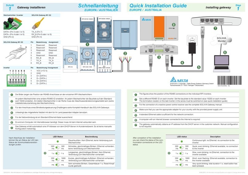
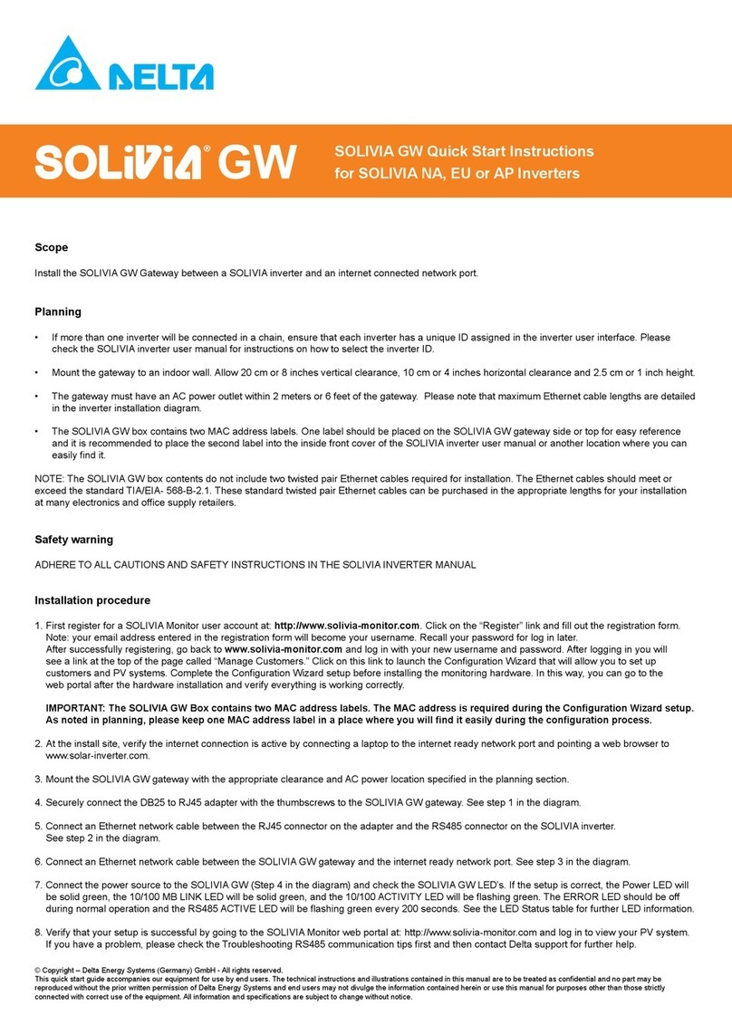
Delta DVW-W02W2-E2 User manual

2016-11-25

i
DVW Series Industrial IEEE 802.11 a/b/g/n
Wireless AP/WDS/Client/Gateway
User Manual
Contents
Chapter 1 Introduction
1.1 Feature.........................................................................................1-4
1.1.1 High Performance Network Technology.......................................1-4
1.1.2 Industrial Grade Reliability........................................................1-4
1.1.3 Robust Design.........................................................................1-4
1.1.4 Front Panel Ports and LEDs .......................................................1-5
1.1.5 Below Panel ............................................................................1-6
1.2 Antenna Installation .......................................................................1-7
1.2.1 Package Checklist....................................................................1-7
Chapter 2 User Interface Introduction
2.1 USB Console Configuration ..............................................................2-2
2.2 Telnet Console Configuration ...........................................................2-7
2.3 Web Browser Configuration .............................................................2-8
Chapter 3 Featured Functions
3.1 System .........................................................................................3-4
3.1.1 System Information.................................................................3-4
3.1.2 System CPU Status..................................................................3-4
3.2 Basic Configuration.........................................................................3-5
3.2.1 System Information Configuration .............................................3-5
3.2.2 Network Configuration .............................................................3-5
3.2.3 Time Configuration ..................................................................3-8
3.2.3.1 Local Time Configuration ......................................................3-8
3.2.3.2 NTP Server Configuration......................................................3-9
3.3 Serial Configuration...................................................................... 3-10
3.3.1 Operation Configuration ......................................................... 3-10
3.3.1.1 MODBUS ASCII/RTU Slave.................................................. 3-10
3.3.1.2 MODBUS ASCII/RTU Master ................................................ 3-12
3.3.1.3 TCP Server Mode............................................................... 3-15

ii
3.3.1.4 TCP Client Mode ................................................................ 3-18
3.3.1.5 Virtual COM Mode.............................................................. 3-23
3.3.1.6 UDP Mode......................................................................... 3-26
3.3.1.7 Pair Connection Mode......................................................... 3-30
3.3.2 Port Configuration ................................................................. 3-32
3.3.3 MODBUS Cache Table ............................................................ 3-33
3.4 WLAN Manager ............................................................................ 3-36
3.4.1 Operation Mode..................................................................... 3-36
3.4.1.1 AP Mode........................................................................... 3-37
3.4.1.2 Client Mode....................................................................... 3-37
3.4.1.3 Repeater Mode.................................................................. 3-37
3.4.1.4 WDS Master and Slave Mode............................................... 3-38
3.4.1.5 Regions............................................................................ 3-38
3.4.2 WLAN................................................................................... 3-39
3.4.2.1 Basic Wireless Configuration – AP Mode................................ 3-39
3.4.2.2 Basic Wireless Configuration – Client Mode ........................... 3-41
3.4.2.3 Basic Wireless Configuration – Repeater Mode....................... 3-42
3.4.2.4 Basic Wireless Configuration – Master Mode.......................... 3-44
3.4.2.5 Basic Wireless Configuration – Slave Mode............................ 3-46
3.4.2.6 Basic Wireless Configuration – Security Mode........................ 3-48
3.4.3 Advanced Wireless Configuration............................................. 3-51
3.5 Advanced.................................................................................... 3-53
3.5.1 VLAN Configuration................................................................ 3-53
3.5.2 Packet Control....................................................................... 3-54
3.5.2.1 Filter Configuration ............................................................ 3-55
3.5.2.2 MAC Filters ....................................................................... 3-55
3.5.2.3 IP Protocol Filters .............................................................. 3-56
3.5.2.4 TCP/UDP Port Filters .......................................................... 3-57
3.5.3 RSTP Configuration................................................................ 3-57
3.5.4 SNMP Configuration ............................................................... 3-58
3.5.5 Storm Control ....................................................................... 3-60
3.6 Auto Warning Settings.................................................................. 3-61
3.6.1 SysLog................................................................................. 3-61
3.6.1.1 Syslog Event Types............................................................ 3-61
3.6.1.2 Syslog Server Configuration................................................ 3-63
3.6.2 E-mail Alarm......................................................................... 3-63
3.6.2.1 E-mail Event Types............................................................ 3-63
3.6.2.2 E-mail Server Configuration ................................................ 3-64

iii
3.6.3 Relay Alarm.......................................................................... 3-65
3.6.3.1 Relay Event Types ............................................................. 3-65
3.6.4 SNMP Trap............................................................................ 3-66
3.6.4.1 Trap Event Types............................................................... 3-66
3.6.4.2 SNMP Trap Receiver Settings .............................................. 3-66
3.7 Monitoring Settings ...................................................................... 3-67
3.7.1 Email Alarm Table ................................................................. 3-67
3.7.2 Relay Alarm Table ................................................................. 3-67
3.7.3 Trap Alarm Table................................................................... 3-68
3.7.4 System Log .......................................................................... 3-68
3.7.5 Network Connection Status..................................................... 3-69
3.7.6 AP Client List......................................................................... 3-69
3.7.7 DHCP Client List .................................................................... 3-69
3.7.8 Serial Port State.................................................................... 3-70
3.7.9 Serial Port Statistics............................................................... 3-70
3.7.10 Serial Port Error .................................................................... 3-70
3.7.11 Serial Port Log ...................................................................... 3-70
3.8 Management Access ..................................................................... 3-71
3.8.1 SSH Configuration ................................................................. 3-71
3.8.2 Telnet Configuration .............................................................. 3-71
3.9 Maintenance................................................................................ 3-72
3.9.1 Session Timeout.................................................................... 3-72
3.9.2 Password.............................................................................. 3-72
3.9.3 Ping..................................................................................... 3-73
3.9.4 Firmware Upgrade ................................................................. 3-74
3.9.5 Log Export............................................................................ 3-74
3.9.6 Config Import Export ............................................................. 3-74
3.9.7 Reset to Default .................................................................... 3-75
3.9.8 Reboot................................................................................. 3-75
3.9.9 Logout ................................................................................. 3-75
Chapter 4 IEXplorer Utility Introduction
4.1 Starting the Configuration ...............................................................4-2
4.1.1 Device....................................................................................4-3
4.1.1.1 Search ...............................................................................4-4
4.1.1.2 Virtual COM ........................................................................4-4
4.1.2 Settings .................................................................................4-5
4.1.2.1 Device Configuration............................................................4-6

iv
4.1.2.2 Configuration Web Page .......................................................4-8
4.1.3 Tools ......................................................................................4-9
4.1.3.1 Parameter Import................................................................4-9
4.1.3.2 Parameter Export .............................................................. 4-10
4.1.3.3 Device Reboot................................................................... 4-10
4.1.3.4 Update Firmware............................................................... 4-11
4.1.4 Help..................................................................................... 4-11
Appendix A Private MIB Group
A.1 Private MIB Group..........................................................................A-2
Appendix B MODBUS TCP Map
B.1 MODBUS TCP Map..........................................................................B-2

1-1
1
Chapter 1 Introduction
Table of Contents
1.1 Feature.......................................................................................................1-4
1.1.1 High Performance Network Technology...................................................... 1-4
1.1.2 Industrial Grade Reliability....................................................................... 1-4
1.1.3 Robust Design........................................................................................ 1-4
1.1.4 Front Panel Ports and LEDs ...................................................................... 1-5
1.1.5 Buttom Panel ......................................................................................... 1-6
1.2 Antenna Installation ..................................................................................1-7
1.2.1 Package Checklist................................................................................... 1-7

DVW Series Industrial IEEE 802.11 a/b/g/n Wireless AP/WDS/Client/Gateway User Manual
1-2
_1
About This Manual
The user manual is suitable for DVW-W02W2-E2 and DVW-W02W2-E2-CN. Owing to the limitation of the radio frequency
policy, if you need to use the Delta DVW series products in China areas, please refer to the model name
DVW-W02W2-E2-CN on the Delta website, or contact our branch offices or distributors.
Federal Communication Commission Interference Statement
This equipment has been tested and found to comply with the limits for a Class Adigital device, pursuant to Part 15 of the
FCC Rules. These limits are designed to provide reasonable protection against harmful interference in a residential
installation. This equipment generates, uses and can radiate radio frequency energy and, if not installed and used in
accordance with the instructions, may cause harmful interference to radio communications. However, there is no
guarantee that interference will not occur in a particular installation. If this equipment does cause harmful interference to
radio or television reception, which can be determined by turning the equipment off and on, the user is encouraged to try
to correct the interference by one of the following measures:
- Reorient or relocate the receiving antenna.
- Increase the separation between the equipment and receiver.
- Connect the equipment into an outlet on a circuit different from that to which the receiver is connected.
- Consult the dealer or an experienced radio/TV technician for help.
FCC Caution:Any changes or modifications not expressly approved by the party responsible for compliance could void
the user's authority to operate this equipment.
This device complies with Part 15 of the FCC Rules. Operation is subject to the following two conditions: (1) This device
may not cause harmful interference, and (2) this device must accept any interference received, including interference that
may cause undesired operation.
Operations in the 5.15-5.25GHz band are restricted to indoor usage only.
This transmitter must not be co-located or operating in conjunction with any other antenna or transmitter.
Radiation Exposure Statement:
This equipment complies with FCC radiation exposure limits set forth for an uncontrolled environment. This equipment
should be installed and operated with minimum distance 20cm between the radiator & your body.
Country Code selection feature to be disabled for products marketed to the US/CANADA.
The equipment intended be used in telecommunication center.

Chapter 1 Product Introduction
1-3
1_
CE Declaration of Conformity
The DVW series switches are CE certificated products, they could use in any kind of the environments under CE
environment specification. For keeping more safe application, we strongly suggest to use the CE-compliant industrial
enclosure products.
NCC 警語
電磁波曝露量 MPE 標準值(MPE) 1mW/cm2,送測產品實值為 0.065mW/cm2
經型式認證合格之低功率射頻電機,非經許可,公司,商號或使用者均不得擅自變更頻率、加大功率或變更原
設計之特性及功能。
低功率射頻電機之使用不得影響飛航安全及干擾合法通信;經發現有干擾現象時,應立即停用,並改善至無干
擾時方得繼續使用。
前項合法通信,指依電信法規定作業之無線電通信。 低功率射頻電機須忍受合法通信或工業、科學及醫療用電
波輻射性電機設備之干擾。
無線傳輸設備 (UNII)
在5.25-5.35 秭赫頻帶內操作之無線資訊傳輸設備,限於室內使用。
無線資訊傳輸設備忍受合法通信之干擾且不得干擾合法通信;如造成干擾,應立即停用,俟無干擾之虞,始得
繼續使用。
無線資訊傳設備的製造廠商應確保頻率穩定性,如依製造廠商使用手冊上所述正常操作,發射的信號應維持於
操作頻帶中。

DVW Series Industrial IEEE 802.11 a/b/g/n Wireless AP/WDS/Client/Gateway User Manual
1-4
_1
1.1 Feature
Thank you for purchasing the DVW Industrial WirelessAP/WDS/Client/Gateway. The DVW series wireless devices are
equipped with the intelligent alarm function, and allow the wide range of operating temperature (-40 to 75℃). The DVW
series devices are designed to support the application in any rugged environment and comply with UL, CE and FCC
standards.
1.1.1 High Performance Network Technology
10/100/1000Base-TX
Auto negotiation speed
Auto MDI/MDI-X
802.11a/b/g/n, up to 450 Mbps
1.1.2 Industrial Grade Reliability
Redundant dual DC power inputs
1 set of Digital Input
1 set of Relay Alarm
1.1.3 Robust Design
Operating temperature: -40~75℃
Storage temperature: -40~85℃
Humidity: 5%~95% (non-condensing)
Protection: IP40

Chapter 1 Product Introduction
1-5
1_
1.1.4 Front Panel Ports and LEDs
Reset Button
RJ45 Ports
Antenna
Serial Ports
USB Console Port
PWR LED
Status LED
DI LED
COM TX/RX LED
Terminal Resistor

DVW Series Industrial IEEE 802.11 a/b/g/n Wireless AP/WDS/Client/Gateway User Manual
1-6
_1
1.1.5 Buttom Panel
Grounding
Screw
PWR Ports
DI
Port
DO
Port

Chapter 1 Product Introduction
1-7
1_
1.2 Antenna Installation
Please connect 3 antennas to the DVW device. You can adjust the direction or angle of the antennas if the wireless signal
is unstable.
1.2.1 Package Checklist
One Delta DVW Wireless AP/WDS/Client Gateway
Omni-directional Antenna x3
Wall mounting Plate x1
USB Type A to Type B console cable x1
User manual and software CD
Instruction Sheet

2-1
2
Chapter 2 User Interface Introduction
Table of Contents
2.1 USB Console Configuration.......................................................... 2-2
2.2 Telnet Console Configuration ...................................................... 2-7
2.3 Web Browser Configuration......................................................... 2-8

DVW Series Industrial IEEE 802.11 a/b/g/n Wireless AP/WDS/Client/Gateway User Manual
2-2
2_
2.1 USB Console Configuration
Delta DVW devices supports configuration using CLI interface, it mainly includes six parts:
1. Exit (Exit this CLI session)
2. Maintenance (some utility commands for maintenance related details)
load_default
3. network_setting (some utility commands for network details)
get_dns get_gateway get_ip_address
get_ip_configuration get_subnet_mask set_dns
set_gateway set_ip_address set_ip_configuration
set_subnet_mask view_setting
4. restart (restart the device)
5. system_info_setting (some utility commands for system information related details)
get_device_contact_info get_device_description get_device_location
get_device_name set_device_contact_info set_device_decription
set_device_location set_device_name view_setting
6. time_setting (some utility commands for time related details)
get_local_time get_timeserver1 get_timeserver2
get_timezone set_local_time set_timeserver1
set_timeserver2 set_timezone view_setting
You can use terminal software to connect to Delta DVW devices. Before you use CLI interface, please plug
USB cable on USB port with baud rate 115200. The inactivity timeout value on a serial port connection can be
configured between 0 and 160 minutes. (Value 0: disable the timeout.)

Chapter 2 User Interface Introduction
2-3
2_
Below is an example to show you how to set the device name.
1. Open terminal software, and select an appropriate COM port for Console Connection, 115200 for Baud
Rate, 8for Data Bits, Nonefor Parity, and 1for Stop Bits, None for Flow Control.
2. Type clash and then press Enter.

DVW Series Industrial IEEE 802.11 a/b/g/n Wireless AP/WDS/Client/Gateway User Manual
2-4
2_
3. Type system_info_setting and then press Enter.
PS. You can make full by use TAB to complete the command that you want to type.
4. Type set_device_name and the new device name, such as “test”, and then press Enter.

Chapter 2 User Interface Introduction
2-5
2_
5. The device name had changed to “test”, you can use “get_device_name” to see it.
6. Type exit to exit this CLI session.

DVW Series Industrial IEEE 802.11 a/b/g/n Wireless AP/WDS/Client/Gateway User Manual
2-6
2_
7. Sometimes if you don’t know how to use the command (such as what does this command mean, or how to
set the parameter in right format, etc), you can type “?” to see the help information.
For example, if you want to set the local time to 2014/02/27 10:11:30, you may know type time_setting and
then type set_local_time, but the next? How should I input the time? You can type ?to see the help
information.
Complete command: “time_setting set_local_time ?” (After you click “?”, the help information will
display.)
8. Finally, you had got to know type 10:11:30 27 02 2014

Chapter 2 User Interface Introduction
2-7
2_
2.2 Telnet Console Configuration
Delta DVW device supports telnet server function; it can be globally enabled or disabled. The user
can use all CLI command over a telnet session.
1. Open a Command Prompt and input “telnet 192.168.1.5” to login to Delta DVW device.
2. After input user name and password, you can use CLI command to control the device.

DVW Series Industrial IEEE 802.11 a/b/g/n Wireless AP/WDS/Client/Gateway User Manual
2-8
2_
2.3 Web Browser Configuration
Delta DVW devices support a friendly web interface for normal user to configure the switch. You can
monitor the port status of Delta DVW device, and configure the settings of each function via web.
1. Open a web browser and connect to 192.168.1.5 or http://www.deltawifi.net. Input user name
and password.
Username: admin
Password: password
2. You can use the menu tree in left side frame to find the function you want to configure. And
configure the detail settings in right side frame. The port status and LED status on the DVW
device can be monitored on the top frame.
This manual suits for next models
1
Table of contents
Other Delta Gateway manuals
Popular Gateway manuals by other brands

TAIKO
TAIKO EzSMS-Lite user manual

Eurotech
Eurotech VOIP ALL SERIES user guide

TEKTELIC Communications
TEKTELIC Communications KONA Enterprise quick start guide

Topex
Topex MobiLink GSM user manual

ProtoCessor
ProtoCessor FieldServer SATEC ProtoNode FPC-N34 Startup guide

Dension
Dension GWL-9201-1 installation guide