Seneca R-GWR User manual

User Manual
R-GWR SERIES
ALL RIGHTS RESERVED. NO PART OF THIS PUBLICATION MAY
BE REPRODUCED WITHOUT PRIOR PERMISSION.
www.seneca.it
Doc: MI00568-1-EN
Page 2
Introduction
The content of this documentation refers to products and technologies described in it.
All technical data contained in the document may be changed without notice.
The content of this documentation is subject to periodic review.
To use the product safely and effectively, read the following instructions carefully before use.
The product must be used only for the use for which it was designed and manufactured: any other use is
under the full responsibility of the user.
Installation, programming and set-up are allowed only to authorized, physically and intellectually suitable
operators.
Set-up must be performed only after correct installation and the user must follow all the operations described
in the installation manual carefully.
Seneca is not responsible for failures, breakages and accidents caused by ignorance or failure to apply the
stated requirements.
Seneca is not responsible for any unauthorized modifications.
Seneca reserves the right to modify the device, for any commercial or construction requirement, without the
obligation to promptly update the reference manuals.
No liability for the contents of this document can be accepted.
Use the concepts, examples and other content at your own risk.
There may be errors and inaccuracies in this document that could damage your system, so proceed with
caution, the author(s) will not take responsibility for it.
Technical specifications are subject to change without notice.
CONTACT US
Technical support
Product information
This document is the property of SENECA srl.
Copies and reproduction are prohibited unless authorised.

User Manual
R-GWR SERIES
ALL RIGHTS RESERVED. NO PART OF THIS PUBLICATION MAY
BE REPRODUCED WITHOUT PRIOR PERMISSION.
www.seneca.it
Doc: MI00568-1-EN
Page 3
Document revisions
DATE
REVISION
NOTES
AUTHOR
24/02/2021
0
First revision
MM
24/03/2021
1
Removed Easy Setup2
software and corrected
the name of Seneca
Discovery Device
AZ

User Manual
R-GWR SERIES
ALL RIGHTS RESERVED. NO PART OF THIS PUBLICATION MAY
BE REPRODUCED WITHOUT PRIOR PERMISSION.
www.seneca.it
Doc: MI00568-1-EN
Page 4
TABLE OF CONTENTS
INTRODUCTION...........................................................................................................51. DESCRIPTION..........................................................................................................................................................................51.1.
COMMUNICATION PORT SPECIFICATIONS.........................................................................................................................61.2.
CONNECTION OF THE DEVICES TO A NETWORK ..................................................72. CONNECTION OF THE DEVICE TO A NETWORK ................................................................................................................72.1.
OPERATING PRINCIPLE.............................................................................................83. SENDING DATA FROM THE SENSORS TO THE R-GWR GATEWAY .................................................................................8
3.1.
COMMUNICATION WITH THE R-GWR GATEWAY................................................................................................................83.2.
AVAILABLE MEASUREMENTS ..............................................................................................................................................93.3.
WEB SERVER OF THE GATEWAY DEVICE ..............................................................94. ACCESS TO THE WEB SERVER ............................................................................................................................................94.1.
DEVICE CONFIGURATION ...................................................................................................................................................104.2.
SETUP SECTION ..............................................................................................................................................................104.2.1.
STATUS SECTION ............................................................................................................................................................124.2.2.
4.2.2.1. PAIRING A NEW SENSOR...........................................................................................................................................13
4.2.2.2. MEANING OF THE STATUS PAGE COLUMNS ..........................................................................................................13
4.2.2.3. CONFIGURING A SENSOR .........................................................................................................................................14
FIRMWARE UPDATE SECTION............................................................................................................................................164.3.
LOCAL TIME SETUP SECTION ............................................................................................................................................164.4.
BATTERY LIFE...........................................................................................................175.
RESETTING THE DEVICE TO FACTORY CONFIGURATION..................................176.
SUPPORTED MODBUS COMMUNICATION PROTOCOLS .....................................187. SUPPORTED MODBUS FUNCTION CODES........................................................................................................................187.1.
MODBUS REGISTER TABLE....................................................................................198. R-GWR: MODBUS 4X HOLDING REGISTERS TABLE (FUNCTION CODE 3) ...................................................................198.1.
SEARCH AND MODIFICATION OF THE DEVICE IP WITH SENECA DISCOVERY
9.
DEVICE .............................................................................................................................40
User Manual
R-GWR SERIES
ALL RIGHTS RESERVED. NO PART OF THIS PUBLICATION MAY
BE REPRODUCED WITHOUT PRIOR PERMISSION.
www.seneca.it
Doc: MI00568-1-EN
Page 5
INTRODUCTION1.
ATTENTION!
This user manual extends the information from the installation manual to the configuration of the
device. Use the installation manual for more information.
ATTENTION!
In any case, SENECA s.r.l. or its suppliers will not be responsible for the loss of data/revenue or
consequential or incidental damages due to negligence or bad/improper management of the device,
even if SENECA is well aware of these possible damages.
SENECA, its subsidiaries, affiliates, group companies, suppliers and distributors do not guarantee that
the functions fully meet the customer's expectations or that the device, firmware and software should
have no errors or operate continuously.
DESCRIPTION1.1.
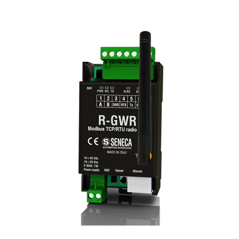
The R-GWR gateway is a device capable of receiving information from radio sensors and making it available
both through the S485/RS232 serial port and through the Ethernet port.
Model
Description
Communication protocols
R-GWR
Radio Gateway with 1 serial port and
1 Ethernet port.
Max 32 Lora sensors.
Modbus TCP-IP
Modbus RTU

User Manual
R-GWR SERIES
ALL RIGHTS RESERVED. NO PART OF THIS PUBLICATION MAY
BE REPRODUCED WITHOUT PRIOR PERMISSION.
www.seneca.it
Doc: MI00568-1-EN
Page 6
COMMUNICATION PORT SPECIFICATIONS1.2.
ETHERNET COMMUNICATION PORTS
Number
1
Type
100 Mbits
RS232/RS485 COMMUNICATION
PORT
Number
1
Baudrate
From 1200 to 115200 bit/s configurable
Parity, Data bit, Stop bit
Configurable
R-GWR COMMUNICATION PROTOCOLS SUPPORTED
Modbus RTU slave
From RS485/RS232 Port
Modbus TCP-IP
From Ethernet

User Manual
R-GWR SERIES
ALL RIGHTS RESERVED. NO PART OF THIS PUBLICATION MAY
BE REPRODUCED WITHOUT PRIOR PERMISSION.
www.seneca.it
Doc: MI00568-1-EN
Page 7
CONNECTION OF THE DEVICES TO A NETWORK2.
CONNECTION OF THE DEVICE TO A NETWORK2.1.
The factory configuration of the IP address is:
Static address: 192.168.90.101
Therefore, multiple devices must not be inserted on the same network with the same static IP.
If you want to connect multiple devices on the same network, you need to change the IP address configuration
via the web server.
ATTENTION!
DO NOT CONNECT 2 OR MORE FACTORY-CONFIGURED DEVICES ON THE SAME NETWORK, OR THE
ETHERNET INTERFACE WILL NOT WORK
(192.168.90.101 IP ADDRESS CONFLICT)
If the addressing mode with DHCP is activated and an IP address is not received within 1 minute, the device
will set an IP address with a fixed error:
169.254.x.y
Where x.y are the last two values of the MAC ADDRESS.
This way it is possible to install more I/O of the R series and then configure the IP with the SENECA
DISCOVERY DEVICE software even on networks without a DHCP server.

User Manual
R-GWR SERIES
ALL RIGHTS RESERVED. NO PART OF THIS PUBLICATION MAY
BE REPRODUCED WITHOUT PRIOR PERMISSION.
www.seneca.it
Doc: MI00568-1-EN
Page 8
OPERATING PRINCIPLE3.
The radio sensors send data via the Lora radio system. This technology allows you to travel long distances
and keep battery consumption at very low levels.
SENDING DATA FROM THE SENSORS TO THE R-GWR GATEWAY3.1.
The radio sensor can send data in two ways:
1) Timed
2) Timed + Event
In mode 1 the sensor sends data with a configurable time interval.
In mode 2 the sensor sends the data with a configurable time interval but, in the event of a digital input event,
it immediately sends the data.
Each R-GWR gateway can manage up to a maximum of 32 sensors.
COMMUNICATION WITH THE R-GWR GATEWAY3.2.
When the gateway receives a packet from an associated sensor it responds with an acknowledge packet.
If the acknowledge packet is not received, the sensor adds a random time (from 1 to 8 seconds) to the next
sending.
If sending an alarm packet (and if sending on "alarm" event is enabled) the sensor makes 5 attempts with a
random delay between them before returning to low consumption again.
When the R-GWR gateway sends the acknowledge packet, it also appends the current configuration (so if you
change the sensor configuration in the gateway this will be sent with the next communication).
When the ALARM parameter is active, an IN0 or IN1 input event immediately activates the sending of the
packet.
ATTENTION!
IT IS ALWAYS POSSIBLE TO FORCE SENDING CURRENT DATA FROM THE SENSOR TO THE
GATEWAY BY PRESSING THE IN3 PAIRING BUTTON.
ATTENTION!
IF THE R-GWR GATEWAY REMAINS OFF FOR A LONG TIME, IT IS NECESSARY TO TURN OFF THE
RADIO SENSORS IN ORDER TO NOT DISCHARGE THE BATTERIES

User Manual
R-GWR SERIES
ALL RIGHTS RESERVED. NO PART OF THIS PUBLICATION MAY
BE REPRODUCED WITHOUT PRIOR PERMISSION.
www.seneca.it
Doc: MI00568-1-EN
Page 9
AVAILABLE MEASUREMENTS3.3.
Depending on the sensor model, the following measurements are available:
SENSOR
TEMP
HUMIDITY
IN0
IN1
IN2
IN3
BATTERY
Sensor
model
Temperat
ure
measure
ment in
°C
Relative
humidity
measurem
ent in %
Configurable
digital/analog
ue input
Configurable
digital input
Tamper
digital input
Pairing
button
status
Battery
status
R-GWR-IP-1
Yes
Yes
Can be
configured
as 0-30V
analogue
measuremen
t or counter
No
No
Yes
Yes
R-GWR-S-1
Yes
Yes
Can be
configured
as 0-30V
analogue
measuremen
t or counter
or Level 1
water
Status of the
reed relay or
Level 2
water
Yes
Connected
to the lid
Yes
Yes
WEB SERVER OF THE GATEWAY DEVICE4.
ACCESS TO THE WEB SERVER4.1.
Access to the web server takes place using a web browser and entering the IP address of the device.
To find out the IP address of the device, use the "search" function of the “SENECA DISCOVERY DEVICE"
software.
On first access the user name and password will be requested.
The default values are:
Username: admin
Password: admin

User Manual
R-GWR SERIES
ALL RIGHTS RESERVED. NO PART OF THIS PUBLICATION MAY
BE REPRODUCED WITHOUT PRIOR PERMISSION.
www.seneca.it
Doc: MI00568-1-EN
Page 10
ATTENTION!
AFTER THE FIRST ACCESS CHANGE USER NAME AND PASSWORD IN ORDER TO PREVENT
ACCESS TO THE DEVICE TO UNAUTHORIZED PEOPLE.
ATTENTION!
IF THE PARAMETERS TO ACCESS THE WEB SERVER HAVE BEEN LOST, IT IS NECESSARY TO
RESET THE FACTORY-SET CONFIGURATION (SEE CHAPTER 6)
DEVICE CONFIGURATION4.2.
To configure the device, access the web server and select the section you are interested in.
After a modification to the configuration has been made, the changes must be confirmed with the "APPLY"
button and the device will restart autonomously.
The Reboot button reboots the device (not necessary in the event of a configuration change).
The Default button returns all the page parameters to the default settings.
SETUP SECTION
4.2.1.
At the top of the screen you can load a previous configuration or save it:

User Manual
R-GWR SERIES
ALL RIGHTS RESERVED. NO PART OF THIS PUBLICATION MAY
BE REPRODUCED WITHOUT PRIOR PERMISSION.
www.seneca.it
Doc: MI00568-1-EN
Page 11
The meaning of the other fields is as follows:
DHCP (default: Disabled)
Sets the DHCP client to get an IP address automatically.
STATIC IP (default: 192.168.90.101)
Sets the device static address. Careful not to enter devices with the same IP address into the same network.
STATIC IP MASK (default: 255.255.255.0)
Sets the mask for the IP network.
STATIC GATEWAY (default: 192.168.90.1)
Sets the gateway address.
MODBUS TCP-IP PORT (default: 502)
Sets the port for the TCP-IP Modbus server.
BAUDRATE MODBUS RTU (SER) (default: 38400 baud)
Sets the baud rate for the RS485 communication port.
DATA MODBUS RTU (SER) (default: 8 bit)
Sets the number of bits for the RS485 communication port.
PARITY MODBUS RTU (SER) (default: None)
Sets the parity for the RS485 communication port.
STOP BIT MODBUS RTU (SER) (default: 1 bit)
Sets the number of stop bits for the RS485 communication port.
PORT TIMEOUT [ms]
Sets the maximum timeout to receive a complete and valid modbus
packet from the serial port.
IP CHANGE DISCOVERY (default: Disabled)
Allows you to enable or not the IP configuration change from the Seneca Discovery Device software.
SYNC CLOCK UPDATE EVERY (default: Day)
Sets the clock synchronization time from the NTP server.
NTP SERVER 1 ADDRESS
Sets the NTP server from which to synchronize the date/time.

User Manual
R-GWR SERIES
ALL RIGHTS RESERVED. NO PART OF THIS PUBLICATION MAY
BE REPRODUCED WITHOUT PRIOR PERMISSION.
www.seneca.it
Doc: MI00568-1-EN
Page 12
NTP SERVER 2 ADDRESS
Sets the backup NTP server from which to synchronize the date/time.
DAYLIGHT SAVING TIME
Selects whether or not to activate the automatic switchover to winter/summer time
GMT
Sets the time zone
WEB SERVER USER NAME (default: admin)
Sets the user name to access the web server.
CONFIGURATION/WEB SERVER PASSWORD (default: admin)
Sets the password to access the web server and to read/write the configuration (if enabled).
WEB SERVER PORT (default: 80)
Sets the communication port for the web server.
STATUS SECTION4.2.2.
In the Status section, you can view the data from the paired radio sensors in real time, pair new sensors,
configure them and remove them from the pairing.

User Manual
R-GWR SERIES
ALL RIGHTS RESERVED. NO PART OF THIS PUBLICATION MAY
BE REPRODUCED WITHOUT PRIOR PERMISSION.
www.seneca.it
Doc: MI00568-1-EN
Page 13
4.2.2.1. PAIRING A NEW SENSOR
To pair one or more new sensors it is necessary to follow the procedure below:
1) Power up the R-GWR gateway and the radio sensor
2) In the gateway press the "START NEW SENSOR PAIRING" button in the "Status" section of the web
server. The STS LED of the gateway will start flashing.
3) In the sensor you want to pair, press and hold the pairing button until the red LED lights up
(transmission).
4) If the green LED of the radio sensor (radio reception) lights up, the association was successful and the
new sensor with its data will appear in the "Status" section of the R-GWR gateway web server.
5) Press the pairing buttons of each sensor you want to pair as in the previous point
6) Once all the sensors have been paired, press the "STOP NEW SENSOR PAIRING" button in the R-
GWR web server “status” section.
7) The STS LED of the R-GWR gateway stops flashing.
4.2.2.2. MEANING OF THE STATUS PAGE COLUMNS
NR SENSOR
Represents the sensor number at the time of pairing.
ADDR SENSOR
Represents the unique address of the sensor (not editable).
LAST SEND
Represents the date/time of the last sending event.
TEMP, HUMIDITY
They represent the temperature and humidity values detected by the sensor respectively.
ANALOG COUNTER
Represents the measurement value of the IN0 input if configured as an analogue input (0-30V) or counter.
IN0
Represents the value of the IN0 input if configured as a digital input.
IN1
Represents the value of the IN1 input if available in the sensor model in use.
IN2
Represents the value of the tamper input if available in the sensor model in use.
IN3
Represents the value of the pairing button.
BATTERY
Represents the state of the battery: OK if the battery is full, FAIL if the battery needs to be replaced.
STATUS

User Manual
R-GWR SERIES
ALL RIGHTS RESERVED. NO PART OF THIS PUBLICATION MAY
BE REPRODUCED WITHOUT PRIOR PERMISSION.
www.seneca.it
Doc: MI00568-1-EN
Page 14
Represents the status of the sensor, if the sensor has not sent the data within the FAIL TIMEOUT time, the
STATUS field goes into fail.
ATTENTION!
IT IS POSSIBLE THAT IN SOME SITUATIONS YOU CANNOT DETECT THE CORRECT STATUS OF THE
BATTERY, AND THEREFORE IT WILL BE DISCHARGED EVEN IF THE STATUS IS OK.
4.2.2.3. CONFIGURING A SENSOR
At each communication, the gateway sends the current configuration to each radio sensor.
ATTENTION!
IF YOU CHANGE THE CONFIGURATION OF A SENSOR IN THE R-GWR WEB SERVER, THIS WILL BE
SENT TO THE SENSOR IN THE NEXT COMMUNICATION
To configure a sensor, press the relative "SETUP" button in the "Status" section of the R-GWR web server:
SEND TIME [ x 30s] (default: 15 minutes)
Represents the time to send data to the gateway in quanta of 30 seconds
INPUT 0 (IN0)
Configures the type of operation of input0 (terminal input):
ALARM-FALLING EDGE = Digital input active in the transition from 1-> 0 of the input signal
ALARM-EDGE = Digital input active in the passage from 1-> 0 and from 0-> 1 of the input signal
COUNTER = The counter on digital input IN0 is activated, the count takes place in the transition from 1-
> 0
WATER SENSOR = The flood detection mode is activated, it also requires the Water Sensor
configuration on INPUT1.
ANALOG INPUT = The 0-30V voltage measurement mode is activated from the IN0 input
INPUT 1 (IN1)
Configures the type of operation of input1 (digital input / magnetic reed relay):
ALARM-REED-RISING EDGE = Digital input active in the transition from 0-> 1 of the input signal
ALARM-REED-FALLING EDGE = Digital input active in the transition from 1-> 0 of the input signal
WATER SENSOR = The flood detection mode is activated

User Manual
R-GWR SERIES
ALL RIGHTS RESERVED. NO PART OF THIS PUBLICATION MAY
BE REPRODUCED WITHOUT PRIOR PERMISSION.
www.seneca.it
Doc: MI00568-1-EN
Page 15
ALARM
Selects whether to activate the radio packet immediate sending mode for inputs IN0 and IN1. It is considered
only for the following operating modes:
INPUT0 = ALARM-RISING EDGE, ALARM-FALLING EDGE or WATER SENSOR
INPUT1 = ALARM-REED-RISING EDGE, ALARM-REED-FALLING EDGE or WATER SENSOR
LINK TX
Sets the transmission power of the radio sensor, selectable between:
0 dB (minimum power, maximum battery life) to 14 dB (maximum power, minimum battery life)
AUTO allows you to automatically calculate the optimal transmission power.
In AUTO mode the sensor performs the following procedure:
1) The sensor sets the minimum power (0 dB) and, at each sending, raises this power
2) When the sensor gets 2 consecutive responses from the gateway it uses this transmission power.
It is therefore possible that there are transmission errors in the initial phase if this mode of operation is used.
The procedure can take from 2 to 5 transmissions to be completed and therefore, based on the sending time
set, it can last several minutes/hours.
To speed up the procedure, it is possible to force communication in the radio sensor by pressing the pairing
button IN3 for at least 5 communications.
To carry out a new procedure it is necessary to follow the following points:
1) Set a transmission power other than AUTO (for example the maximum power of 14 dB)
2) Forcing a communication in the radio sensor (pressing the IN3 pairing button)
3) Set the transmission power back to AUTO
4) Forcing a communication in the radio sensor (pressing the IN3 pairing button)
At this point the procedure for calculating the optimal transmission power will begin.
FAIL MODE
LAST VALUE = In case of sensor fail (communication timeout) the gateway keeps the last values sent
by the radio sensor
LOAD FAIL VALUE = In case of sensor fail (communication timeout) the gateway loads the fail values
FAIL TIMEOUT [x 30s]
Sets the fail time after which, if there has been no communication, the sensor is considered to be in a fail
state. Sets this time so that it is always greater than the sensor send time (SEND TIME).
FAIL VALUE “CNT0/ANG0”, “TEMP”, “HUMIDITY”, “INPUT0”, “INPUT1”, “INPUT2”, “INPUT3”
Sets the value to load in case of fail in the respective variable

User Manual
R-GWR SERIES
ALL RIGHTS RESERVED. NO PART OF THIS PUBLICATION MAY
BE REPRODUCED WITHOUT PRIOR PERMISSION.
www.seneca.it
Doc: MI00568-1-EN
Page 16
INHIBITION TIME [min]
Sets whether or not to enable the inhibition for inputs IN0 and IN1 when they are configured as "alarm" (on
event). Any event that occurs before this time has expired from the previous one is ignored. If enabled, it is
possible to choose an inhibition time between 5 and 75 minutes.
An event that occurs before the inhibition time has expired reloads the inhibition time. For example, if the
inhibition time is 5 minutes and a new event occurs after 4 minutes, the inhibition is reset for another 5
minutes.
FIRMWARE UPDATE SECTION4.3.
The “Firmware Update” section allows you to update the device firmware in order to obtain new functions.
ATTENTION!
NOT TO DAMAGE THE DEVICE DO NOT REMOVE THE POWER SUPPLY DURING THE FIRMWARE
UPDATE OPERATION.
LOCAL TIME SETUP SECTION4.4.
Allows you to set the current date/time in case it is not possible to access the NTP servers.
The date is now kept for a few days even when the device is not powered.

User Manual
R-GWR SERIES
ALL RIGHTS RESERVED. NO PART OF THIS PUBLICATION MAY
BE REPRODUCED WITHOUT PRIOR PERMISSION.
www.seneca.it
Doc: MI00568-1-EN
Page 17
BATTERY LIFE5.
Battery life depends on:
the type of installation.
the type of configuration.
the temperature.
how good the battery is.
how good the radio link is.
The following table is calculated as follows:
without sensor input connections
at a temperature of 20°C
with signal transmitted at 15 dB (maximum power)
SENSOR
TYPICAL
BATTERY
CAPACITY AT
20°C
MAXIMUM ESTIMATED LIFE
SENDING EVERY
60 MIN
SENDING
EVERY 30 MIN
SENDING
EVERY 15 MIN
SENDING
EVERY 10
MIN
SENDING
EVERY 1
MIN
R-GWR-S-1
CR2
900 mAh
Up to 680 days
Up to 500
days
Up to 320 days
Up to 230
days
Up to 28
days
R-GWR-IP-1
CR123A
1650 mAh
Up to 1280 days
Up to 920
days
Up to 590 days
Up to 430
days
Up to 52
days
RESETTING THE DEVICE TO FACTORY CONFIGURATION6.
It is possible to reset the device to the factory configuration using the following procedure:
1) With the device off, set dip switch SW2 dip 1 and 2 to ON
2) Power up the device and wait 10 seconds
3) Turn off the device
4) With the device off, set dip switch SW2 dip 1 and 2 to OFF
5) Power up the device
6) The device has now been reset to the factory configuration

User Manual
R-GWR SERIES
ALL RIGHTS RESERVED. NO PART OF THIS PUBLICATION MAY
BE REPRODUCED WITHOUT PRIOR PERMISSION.
www.seneca.it
Doc: MI00568-1-EN
Page 18
SUPPORTED MODBUS COMMUNICATION PROTOCOLS7.
The Modbus communication protocols supported are:
Modbus RTU Slave (from the RS485/RS232 port)
Modbus TCP-IP Server (from Ethernet port) max 8 client
For more information on these protocols, see the website:
http://www.modbus.org/specs.php.
SUPPORTED MODBUS FUNCTION CODES7.1.
The following Modbus functions are supported:
Read Holding Register (function 3)
ATTENTION!
All 32-bit values are contained in 2 consecutive registers
ATTENTION!
Any registers with RW* (in flash memory) can be written up to 10000 times
The PLC/Master Modbus programmer must not exceed this limit

User Manual
R-GWR SERIES
ALL RIGHTS RESERVED. NO PART OF THIS PUBLICATION MAY
BE REPRODUCED WITHOUT PRIOR PERMISSION.
www.seneca.it
Doc: MI00568-1-EN
Page 19
MODBUS REGISTER TABLE8.
The following abbreviations are used in the register tables:
MS = More significant
LS = Less significant
MSW = 16 most significant bits
LSW = 16 least significant bits
RO = Register in read-only
RW = Read/write register
RW * = Register in reading and writing contained in flash memory, writable a maximum of 10000 times.
Unsigned 16 bit = unsigned integer register, can take values from 0 to 65535
Signed 16 bit = signed integer register can take values from -32768 to +32767
Float 32 bits = Single-precision floating point register with 32 bits (IEEE 754)
https://en.wikipedia.org/wiki/IEEE_754
BIT = Boolean registry, can be 0 (false) or 1 (true)
R-GWR: MODBUS 4X HOLDING REGISTERS TABLE (FUNCTION CODE 3)8.1.
ADDRESS
(4x)
OFFSET
ADDRESS
(4x)
REGISTER
SENSOR
DESCRIPTION
W/R
TYPE
40001
0
MACHINE ID
-
Device ID
RO
UNSIGNED
16 BIT
40002
1
FW REVISION
-
FW revision
RO
UNSIGNED
16 BIT
40003
2
HW REVISION
-
HW revision
RO
UNSIGNED
16 BIT
40004
3
RESERVED
-
-
RO
UNSIGNED
16 BIT
40005
4
RESERVED
-
-
RW
UNSIGNED
16 BIT
40006
5
RESERVED
-
-
RW
UNSIGNED
16 BIT
40007
6
RESERVED
-
-
RW
UNSIGNED
16 BIT
40008
7
RESERVED
-
-
RW
UNSIGNED
16 BIT
40009
8
RESERVED
-
RW
UNSIGNED
16 BIT
40010
9
RESERVED
-
RW
UNSIGNED
16 BIT

User Manual
R-GWR SERIES
ALL RIGHTS RESERVED. NO PART OF THIS PUBLICATION MAY
BE REPRODUCED WITHOUT PRIOR PERMISSION.
www.seneca.it
Doc: MI00568-1-EN
Page 20
ADDRESS
(4x)
OFFSET
ADDRESS
(4x)
REGISTER
SENSOR
DESCRIPTION
W/R
TYPE
40550
549
SENSOR SERIAL CODE
1
Sensor serial code
MSW
RO
UNSIGNED
32
40551
550
Sensor serial code
LSW
RO
40552
551
SENSOR SIGNAL LEVEL
1
Signal level
0 = minimum
6 = maximum
RO
UNSIGNED
16 BIT
40553
552
SENSOR SERIAL CODE
2
Sensor serial code
MSW
RO
UNSIGNED
32
40554
553
Sensor serial code
LSW
RO
40555
554
SENSOR SIGNAL LEVEL
2
Signal level
0 = minimum
6 = maximum
RO
UNSIGNED
16 BIT
40556
555
SENSOR SERIAL CODE
3
Sensor serial code
MSW
RO
UNSIGNED
32
40557
556
Sensor serial code
LSW
RO
40558
557
SENSOR SIGNAL LEVEL
3
Signal level
0 = minimum
6 = maximum
RO
UNSIGNED
16 BIT
40559
558
SENSOR SERIAL CODE
4
Sensor serial code
MSW
RO
UNSIGNED
32
40560
559
Sensor serial code
LSW
RO
40561
560
SENSOR SIGNAL LEVEL
4
Signal level
0 = minimum
6 = maximum
RO
UNSIGNED
16 BIT
40562
561
SENSOR SERIAL CODE
5
Sensor serial code
MSW
RO
UNSIGNED
32
40563
562
Sensor serial code
LSW
RO
40564
563
SENSOR SIGNAL LEVEL
5
Signal level
0 = minimum
6 = maximum
RO
UNSIGNED
16 BIT
40565
564
SENSOR SERIAL CODE
6
Sensor serial code
MSW
RO
UNSIGNED
32
40566
565
Sensor serial code
LSW
RO
Other manuals for R-GWR
1
Table of contents
Other Seneca Gateway manuals

Seneca
Seneca Z-KEY-MBUS User manual

Seneca
Seneca R-GWR User manual

Seneca
Seneca Z-KEY MBUS User manual

Seneca
Seneca Z-KEY-P User manual

Seneca
Seneca Z-KEY User manual

Seneca
Seneca R-KEY-LT User manual

Seneca
Seneca Z-PASS2 User manual

Seneca
Seneca Z-GW-MB User manual

Seneca
Seneca Z-KEY-MBUS User manual

Seneca
Seneca Z-KEY User manual

Seneca
Seneca X-HDU Instruction Manual

Seneca
Seneca R-PASS User manual

Seneca
Seneca Z-PC SERIES User manual

Seneca
Seneca Z-PASS2-IO User manual

Seneca
Seneca Z-PASS1-R02 User manual

Seneca
Seneca Z-KEY-2ETH-P User manual

Seneca
Seneca Z-KEY User manual

Seneca
Seneca Z-LINK2-LO User manual

Seneca
Seneca R-KEY-LT User manual

Seneca
Seneca Z-KEY-P User manual