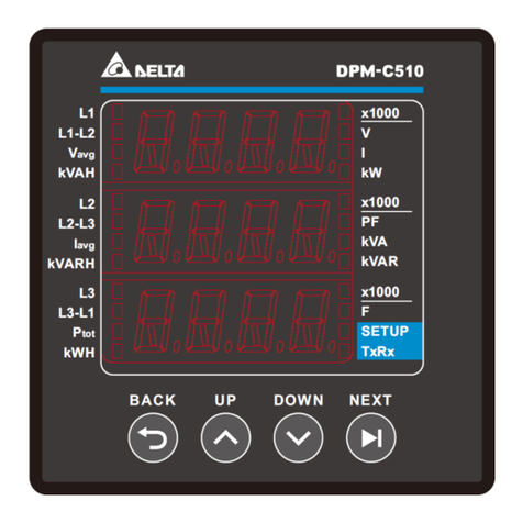
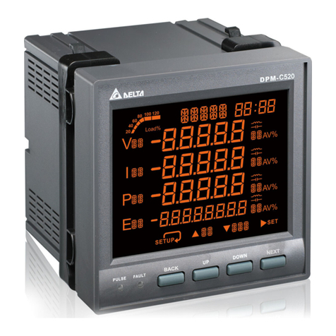
Delta DPM-C530 User manual

Multi-functional Power Meter DPM-C530 Operation Manual
Industrial Automation Headquarters
Delta Electronics, Inc.
Taoyuan Technology Center
No.18, Xinglong Rd., Taoyuan District,
Taoyuan City 33068, Taiwan
TEL: 886-3-362-6301 / FAX: 886-3-371-6301
Asia
Delta Electronics (Shanghai) Co., Ltd.
No.182 Minyu Rd., Pudong Shanghai, P.R.C.
Post code : 201209
TEL: 86-21-6872-3988 / FAX: 86-21-6872-3996
Customer Service: 400-820-9595
Delta Electronics (Japan), Inc.
Tokyo Oce
Industrial Automation Sales Department
2-1-14 Shibadaimon, Minato-ku
Tokyo, Japan 105-0012
TEL: 81-3-5733-1155 / FAX: 81-3-5733-1255
Delta Electronics (Korea), Inc.
Seoul Oce
1511, 219, Gasan Digital 1-Ro., Geumcheon-gu,
Seoul, 08501 South Korea
TEL: 82-2-515-5305 / FAX: 82-2-515-5302
Delta Energy Systems (Singapore) Pte Ltd.
4 Kaki Bukit Avenue 1, #05-04, Singapore 417939
TEL: 65-6747-5155 / FAX: 65-6744-9228
Delta Electronics (India) Pvt. Ltd.
Plot No.43, Sector 35, HSIIDC Gurgaon,
PIN 122001, Haryana, India
TEL: 91-124-4874900 / FAX : 91-124-4874945
Delta Electronics (Thailand) PCL.
909 Soi 9, Moo 4, Bangpoo Industrial Estate (E.P.Z),
Pattana 1 Rd., T.Phraksa,A.Muang,
Samutprakarn 10280, Thailand
TEL: 66-2709-2800 / FAX : 662-709-2827
Delta Energy Systems (Australia) Pty Ltd.
Unit 20-21/45 Normanby Rd., Notting Hill Vic 3168,Australia
TEL: 61-3-9543-3720
Americas
Delta Electronics (Americas) Ltd.
Raleigh Oce
P.O. Box 12173, 5101 Davis Drive,
Research Triangle Park, NC 27709, U.S.A.
TEL: 1-919-767-3813 / FAX: 1-919-767-3969
Delta Greentech (Brasil) S/A
São Paulo Oce
Rua Itapeva, 26 – 3˚ Andar - Bela Vista
CEP: 01332-000 – São Paulo – SP - Brasil
TEL: 55-11-3530-8642 / 55-11-3530-8640
Delta Electronics International Mexico S.A. de C.V.
Mexico Oce
Vía Dr. Gustavo Baz No. 2160, Colonia La Loma,
54060 Tlalnepantla Estado de Mexico
TEL: 52-55-2628-3015 #3050/3052
*We reserve the right to change the information in this catalogue without prior notice.
DPM-093AA20-02
EMEA
Delta Electronics (Netherlands) BV
Eindhoven Oce
De Witbogt 20, 5652 AG Eindhoven, The Netherlands
MAIL: Sales.IA.EMEA@deltaww.com
MAIL: Sales.IA.Benelux@deltaww.com
Delta Electronics (France) S.A.
ZI du bois Chaland 2 15 rue des Pyrénées,
Lisses 91056 Evry Cedex, France
MAIL: Sales.IA.FR@deltaww.com
Delta Electronics Solutions (Spain) S.L.U
Ctra. De Villaverde a Vallecas, 265 1˚ Dcha Ed.
Hormigueras – P.I. de Vallecas 28031 Madrid
C/Llull, 321-329 (Edici CINC) | 22@Barcrelona, 08019 Barcelona
MAIL: Sales.IA.Iberia@deltaww.com
Delta Electronics (Italy) Srl
Ucio di Milano Via Senigallia 18/2 20161 Milano (MI)
Piazza Grazioli 18 00186 Roma, Italy
MAIL: Sales.IA.Italy@deltaww.com
Delta Electronics (Germany) GmbH
Coesterweg 45, D-59494 Soest, Germany
MAIL: Sales.IA.DACH@deltaww.com
Delta Energy Systems LLC (CIS)
Vereyskaya Plaza II, oce 112 Vereyskaya str.
17 121357 Moscow, Russia
MAIL: Sales.IA.RU@deltaww.com
Delta Greentech Elektronik San. Ltd. Sti. (Turkey)
Serifali Mah. Hendem Cad. Kule Sok. No: 16-A
34775 Umraniye / Istanbul
MAIL: Sales.IA.Turkey@deltaww.com
Delta Energy Systems AG (Dubai BR)
P.O. Box 185668, Gate 7, 3rd Floor, Hamarain Centre,
Dubai, United Arab Emirates
MAIL: Sales.IA.MEA@deltaww.com
2018/09/26
DPM-C530 Operation Manual
Revision History
Version
Revision
Date
1
st
The first version was published.
2018/08/24
2nd
Error correction
2018/09/26

i
DPM-C530 Operation Manual
Table of Contents
Chapter 1 Product Introduction
1.1 Preface ..............................................................................................1-2
1.2 Overview ...........................................................................................1-2
1.3 Safety Precautions.............................................................................1-3
Chapter 2 Product Specifications
2.1 Electrical Characteristics ...................................................................2-2
2.2 Communications Specifications .........................................................2-4
2.3 Operating the Display........................................................................2-4
2.3.1 Menu Tree..................................................................................... 2-5
2.4 Dimensions........................................................................................2-6
Chapter 3 Installation
3.1 Installation........................................................................................3-2
3.1.1 Installation Environment................................................................. 3-2
3.1.2 Installation Notes........................................................................... 3-2
3.2 Basic Checks......................................................................................3-4
3.3 Wiring................................................................................................3-4
3.3.1 Wiring Diagrams............................................................................ 3-4
3.3.2 Communication Characteristics........................................................ 3-6
Chapter 4 Operation
4.1 General Operation .............................................................................4-2
4.1.1 Setting Menu................................................................................. 4-2
4.2 Basic Setups ......................................................................................4-3
4.2.1 Set up the Time and Date ............................................................... 4-3
4.2.2 Meter Information.......................................................................... 4-3
4.2.3 Set up the Communication.............................................................. 4-3
4.2.4 Set up the Transformer Ratio........................................................... 4-4
4.2.5 Set up the System ......................................................................... 4-5

ii
4.2.6 Set up the Alarms.......................................................................... 4-6
4.2.7 Set up the Demands ...................................................................... 4-7
4.2.8 Set up the Resets .......................................................................... 4-8
4.3 Advanced Setups ...............................................................................4-8
4.3.1 Set up the Auto Recording .............................................................. 4-8
4.3.2 Set up the Data Log....................................................................... 4-9
4.3.3 Set up the Auto MaxMin.................................................................4-10
4.3.4 Set up the Groups.........................................................................4-10
4.4 Power Analysis Values.....................................................................4-11
4.4.1 Total Harmonic Distortion Measurement...........................................4-11
4.4.2 Demand Calculation Method...........................................................4-12
Chapter 5 Parameters and Funcitons
5.1 Overview of Parameters ....................................................................5-2
Chapter 6 Error Codes
6.1 Error Codes........................................................................................6-2
6.2 Alarm Types ......................................................................................6-2
Appendix A Accessories
A.1 DCT1000 Series .................................................................................A-2
A.2 DCT2000 Series .................................................................................A-4

1-1
1
Chapter 1 Product Introduction
Table of Contents
1.1 Preface ..............................................................................................1-2
1.2 Overview ...........................................................................................1-2
1.3 Safety Precautions.............................................................................1-3
1

DPM-C530 Operation Manual
1-2
_1
_1
1.1 Preface
Thank you for choosing this product. This manual provides installation instructions for the DPM-C530 power
meter. The multifunction power meter DPM-C530 is an obvious choice for any application in terms of power
monitoring and control. It also can be used for measurement category CAT III.
Before using the meter, read this manual carefully to ensure proper use of this meter. Before you finish reading
this manual, observe the following notes.
The installation environment must be free of water vapor, corrosive and flammable gas.
Follow the instructions on the diagram in this manual for wiring the device.
Grounding must be performed correctly and properly according to provisions for related electric work
regulations currently effective in the country.
Do not disassemble the meter or alter its wiring when the power is on.
When the power is on, do not touch the terminal area to avoid electric shock.
If you still experience issues when using the device, please contact your distributor or our customer service
center. As the product is updated and improved, changes to the specifications will be included in the newest
version of the manual which you can get by contacting your distributor or downloading it from the Delta
Electronics website (http://www.delta.com.tw/ia/).
1.2 Overview
The DPM-C530 is equipped with a large, back-lit LCD display that displays up to four lines of information.

Chapter 1 Product Introduction
1-3
1_
1_
1.3 Safety Precautions
Installation Notes
Install the power meter according to instructions on the manual. Use appropriate
personal protective equipment (PPE) and follow safe electrical work practices.
Only qualified electrical workers should install this equipment. Such work should be
performed only after reading the entire set of installation instructions.
Operate the power meter according to instructions on the manual. Neglecting
fundamental installation requirements may lead to personal injury as well as damage
to electrical equipment or other property.
This equipment should be installed in a suitable insulated and fireproof enclosure.
Operation Notes
DO NOT work alone.
Before performing visual inspections, tests, or maintenance on this equipment,
disconnect all electric power sources.
Always use a properly rated voltage sensing device to confirm that power is off.
Replace all devices, doors and covers before turning on power to this equipment.
Carefully inspect the work area for tools and objects that may have been left inside
the equipment.
Operation Notes
Never short the secondary of a Power Transformer (PT).
Never open circuit a Current Transformer (CT)
Ensure that the CT secondary winding is fixed securely on the equipment. It may
damage the equipment if the secondary winding becomes loose during operation.
When used with CTs, make sure the CTs are UL2808 listed in America and Canada
and meet or exceed the accuracy specifications for IEC61869-2 class or accepted by
authority having jurisdiction (AHJ) in other areas.
Wiring Notes
When the measured current is higher than the rated specification for the device,
consider using an external current transformer (CT).
When the measured voltage is higher than the rated specification for the device,
consider using an external potential transformer (PT) (line voltage: 35 to 690V AC L-L
or phase voltage: 20 to 400V AC L-N).
Connect only one cord to one plug on the quick connector.
For the device is accidently unplugged, check the connecting cord and restart.
Maintenance and Inspection Notes
While cleaning the equipment, be sure to unplug all external power sources first. Use
a dry cloth to clean the equipment’s exterior. DO NOT open the equipment or touch
the wiring inside to prevent personal injury as well as damage to electrical equipment
or other property. DO NOT use aerosol sprays, solvents, or abrasives.

DPM-C530 Operation Manual
1-4
_1
_1
MEMO

2-1
2
Chapter 2Product Specifications
Table of Contents
2.1 Electrical Characteristics.....................................................................2-2
2.2 Communications Specifications...........................................................2-4
2.3 Operating the Display..........................................................................2-4
2.3.1 Menu Tree..................................................................................... 2-5
2.4 Dimensions .........................................................................................2-6

DPM-C530 Operation Manual
2-2
_2
2.1 Electrical Characteristics
Input
Voltage Connection
1PH2W, 1 CT 3PH3W, Δconnection, 3 CT, 2 PT
1PH3W, 2 CT 3PH4W, Y connection, 3 CT, No PT
3PH3W, Δconnection, 3 CT, No PT 3PH4W, Y connection, 3 CT, 3 PT
3PH3W, Δconnection, 2 CT, No PT 3PH4W, Y connection, 2 CT, 3 PT
Rated Voltage Line voltage: 35–690 VAC (L-L)
Phase voltage: 20–400 VAC (L-N)
Rated Current 1 A / 5 A
Frequency 50/60 Hz
Harmonic Distortion
for Individual
Current/Voltage
21
Voltage Input Measuring Category: CAT III
Alarm Set up multi-level alarms 10 multi-level alarms
Power Operating range 80–265 VAC (maximum power: 4.6 W)
100–300 VDC
Frequency Operating frequency 50/60 Hz
Communication RS-485 port
Modbus-RTU, Modbus ASCII, BACnet
MS/TP
Baud rate 9600 / 19200 / 38400 bps
Measurement Accuracy
Electric quantities
Voltage, current ± 0.5% Electric
energy
Real power ± 0.5%
Real power, reactive
power, apparent power
± 0.5% Reactive
power ± 0.5%
Power factor ± 0.5% Total Harmonic
Distortion for Current ± 1%
Real power ± 0.5% Total Harmonic
Distortion for Voltage ± 1%
Reactive power ± 0.5% Frequency ± 0.5%
Apparent power ± 0.5% Harmonic ± 1%

Chapter 2 Product Specifications
2-3
2_
Mechanical
Characteristics
Dimension (W x H x D) 96 x 96 x 95.4 mm
IP Degree of Protection IP52 (front display), IP20 (meter body)
Environment
Ambient operating temperature -20–60°C (-4–144°F)
Storage temperature -30–70 °C (-22–158°F)
Relative Humidity 5–95% RH
Altitude Below 2000 meters
Data Recording
Maximum / Minimum
Instantaneous Values 39 / 39
Alarm Type 29
Alarms History 40
Display
Screen Type LCD
Backlight White LED
Resolution 198 x 160 pixels
LED Indicator Green: pulse light ; Red: fault light
Electromagnetic Compatibility
Electrostatic Discharge IEC 61000-4-2
Immunity to Radiated Fields IEC 61000-4-3
Immunity to Fast Transients IEC 61000-4-4
Immunity to Impulse Waves IEC 61000-4-5
Conducted Immunity IEC 61000-4-6
Immunity to Magnetic Fields IEC 61000-4-8
Immunity to Voltage Dips IEC 61000-4-11
Radiated Emissions FCC Part 15 Class A, EN55011 Class A
Conducted Emissions FCC Part 15 Class A, EN55011 Class A
Harmonics IEC 61000-3-2

DPM-C530 Operation Manual
2-4
_2
2.2 Communications Specifications
Communications
RS-485 Modbus-RTU, Modbus ASCII, BACnet MS/TP
Baud rate 9600 / 19200 / 38400 bps
2.3 Operating the Display
A
Title
B
Display area
C
PULSE light
D
FAULT light
E
MENU key
F
UP Key
G
DOWN Key
H
ENTER Key
Button Basic Mode Setting Mode
MENU Key Go to Menu or return to the previous
screen
Return to the previous screen without
saving the current setting
UP Key Select item or page Increment the number
DOWN Key Select item or page Decrement the number
ENTER Key Go to setting mode Go to setting mode and go to the next
setting

Chapter 2 Product Specifications
2-5
2_
2.3.1 Menu Tree
Display Menu Tree
0.Setting
1.Voltage Measure
2.Current Measure
3. PF/Hz
4.Power Measure
5.Energy Measure
6.Harmonic
7.Demand
8.Maximum
9.Minimum
10.Alarm
11.Advanced
Voltage L-N Voltage L-L Voltage
Unbalanced L-N
Current Current
Unbalanced
Power Factor Displacement
PF Frequency
Total Power Active Power Apparent
Power
Active
Energy
Total
Harmonic Current THD Voltage
THD L-N
Current
Demand Active
Power Demand
History
1. Time, Date
2. Meter Info
3. Communication
4. Transformer Ratio
5. System
6. Alarm
7. Demand
8. Reset
1.Current
2.
3. Power
4. Power Factor
5.Frequency
6. Harmon ics
1.
2. Voltage
3. Power
4. Power Factor
5.Frequency
6. Harmonics
1. Floor Area
2. Auto Recording
3. Data Log
4. Max/Min
Auto Reset
Automatic
Energy 1
1
Voltage
THD L-L
9.Change Password
Time of Use
Energy Saving
5. Wh Per Hour
6.
Default
Main Page
MENU
Reactive
Energy
Reactive
Power Demand Apparent
Power Demand
Apparent
Energy
Reactive
Power
Voltage
Unbalanced L-L
Automatic
Energy 2
Current
Voltage
Time of Use

DPM-C530 Operation Manual
2-6
_2
2.4 Dimensions
Front
Unit: mm
Back:
Unit: mm

3-1
3
3
Chapter 3 Installation
Table of Contents
3.1 Installation .........................................................................................3-2
3.1.1 Installation Environment................................................................. 3-2
3.1.2 Installation Notes........................................................................... 3-2
3.2 Basic Checks .......................................................................................3-4
3.3 Wiring .................................................................................................3-4
3.3.1 Wiring Diagrams............................................................................ 3-4
3.3.2 Communication Characteristics ........................................................ 3-6

DPM-C530 Operation Manual
3-2
_3_3
3.1 Installation
3.1.1 Installation Environment
Keep the product in the shipping carton before installation. Store the product properly when it is not to be used
for an extended period of time to retain the warranty coverage. Some storage suggestions are listed below.
Store the power meter in a clean, dry, and controlled environment.
Store in an ambient temperature range of -30–70°C (-22–158°F).
Store in a relative humidity range of 5–95%, non-condensing.
Do not store the product in a place subjected to corrosive gases or liquids.
Place the product on a solid and durable surface.
Do not mount the product near heat-radiating elements; or in a location subjected to corrosive gases,
liquids, airborne dust or metallic particles; or where it can be subjected to high levels of electromagnetic
radiation.
3.1.2 Installation Notes
Follow the instruction when installing the product to prevent equipment breakdown.
To increase the cooling efficiency, install the product with sufficient space between adjacent objects and
baffles and walls to prevent poor heat dissipation.
The maximum panel thickness should be 4.0 mm.
Installation Steps
Step 1: Before installing the power meter, open the square hole on the metal plate.
Step 2: Push the meter into the hole and then slide the securing bracket in to the metal plate.

Chapter 3 Installation
3-3
3_
Step 3: Allow 50 mm (2 inches) of clearance at the back of the meter for heat dissipation.
Mounting Hole Dimensions
Unit: mm

DPM-C530 Operation Manual
3-4
_3_3
3.2 Basic Checks
Items
Contents
General Check
Regularly check for mounting looseness where the power meter and device are
connected.
Prevent foreign objects, such as oil, water, or metal powder entering the device through
the ventilation holes. Prevent drill shavings or other debris entering the power meter.
If the power meter is installed at a location with harmful gas or dust, prevent those
materials from entering the power meter.
Pre-operation
Check
(not supplied
with power)
Insulate the connections at the wiring terminals.
Communications wiring should be done properly to prevent abnormal operations.
Check for the presence of conducive and flammable objects, such as screws or metal
pieces in the power meter.
If electronic devices near to the power meter experience electromagnetic interference,
take steps to reduce the electromagnetic interference.
Check for the correct voltage level for the power supplied to the power meter.
Pre-running
Check
(supplied with
power)
Check if the power indicator light is lit.
Check if communication between every device is normal.
If there is any abnormal response from the power meter, contact your distributor or our
customer service center.
3.3 Wiring
3.3.1 Wiring Diagrams
To avoid electric shock, do not change the wiring when the power is on.
Install a breaker switch on the power cord for the meter because there is no power switch on the power
meter.
When the measured voltage is higher than the rated specification for the device, it is necessary to use an
external potential transformer (PT).
When the measured current is higher than the rated specification for the device, it is necessary to use an
external current transformer (CT).
The following table shows the recommended wiring materials.
Connecting Terminals
Wire Diameters
Screw Turning Torque
Temperature rating
Operating Power AWG 10–24 7.14 kgf-cm (0.7 N·m) above 70°C
Voltage Measurement AWG 10–24 7.14 kgf-cm (0.7 N·m) above 70°C
Current Measurement
AWG 14–22
8.0 kgf-cm (0.79 N·m)
above 70°C
RS-485 AWG 14–28 2.04 kgf-cm (0.2 N·m) above 70°C
Table of contents
Other Delta Measuring Instrument manuals

Delta
Delta HD2114.0 User manual

Delta
Delta RetroSign GR1 User manual

Delta
Delta DVP-ES2 User manual

Delta
Delta CS-LDM-50M User manual

Delta
Delta RetroSign GR1 User manual

Delta
Delta dvp04pt-s User manual

Delta
Delta RetroSign GRX-1 User manual

Delta
Delta DPM-D510 User manual

Delta
Delta HD2114P.0 User manual

Delta
Delta RetroSign GRX User manual

Delta
Delta RetroSign GR1 User manual

Delta
Delta WS-6975 User manual

Delta
Delta R4E User manual

Delta
Delta DPM-C501L User manual

Delta
Delta HD2105.2 User manual

Delta
Delta DPM-D520I User manual

Delta
Delta DPM-C320 User manual

Delta
Delta DPM-C510 User manual

Delta
Delta UNO-C07X011 User manual

Delta
Delta EMS 32-011 User manual