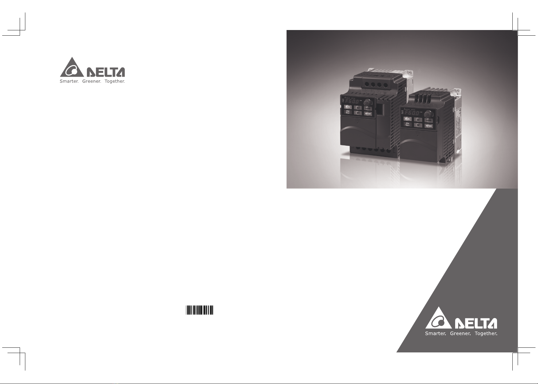
Delta VFD-E Series User manual

Sensorless Vector
Control Compact Drive
VFD-E Series User Manual
www.deltaww.com
Industrial Automation Headquarters
Delta Electronics, Inc.
Taoyuan Technology Center
No.18, Xinglong Rd., Taoyuan City,
Taoyuan County 33068, Taiwan
TEL: 886-3-362-6301 / FAX: 886-3-371-6301
Asia
Delta Electronics (Jiangsu) Ltd.
Wujiang Plant 3
1688 Jiangxing East Road,
Wujiang Economic Development Zone
Wujiang City, Jiang Su Province,
People's Republic of China (Post code: 215200)
TEL: 86-512-6340-3008 / FAX: 86-769-6340-7290
Delta Greentech (China) Co., Ltd.
238 Min-Xia Road, Pudong District,
ShangHai, P.R.C.
Post code : 201209
TEL: 86-21-58635678 / FAX: 86-21-58630003
Delta Electronics (Japan), Inc.
Tokyo Office
2-1-14 Minato-ku Shibadaimon,
Tokyo 105-0012, Japan
TEL: 81-3-5733-1111 / FAX: 81-3-5733-1211
Delta Electronics (Korea), Inc.
1511, Byucksan Digital Valley 6-cha, Gasan-dong,
Geumcheon-gu, Seoul, Korea, 153-704
TEL: 82-2-515-5303 / FAX: 82-2-515-5302
Delta Electronics Int’l (S) Pte Ltd
4 Kaki Bukit Ave 1, #05-05, Singapore 417939
TEL: 65-6747-5155 / FAX: 65-6744-9228
Delta Electronics (India) Pvt. Ltd.
Plot No 43 Sector 35, HSIIDC
Gurgaon, PIN 122001, Haryana, India
TEL : 91-124-4874900 / FAX : 91-124-4874945
Americas
Delta Products Corporation (USA)
Raleigh Office
P.O. Box 12173,5101 Davis Drive,
Research Triangle Park, NC 27709, U.S.A.
TEL: 1-919-767-3800 / FAX: 1-919-767-8080
Delta Greentech (Brasil) S.A
Sao Paulo Office
Rua Itapeva, 26 - 3° andar Edificio Itapeva One-Bela Vista
01332-000-São Paulo-SP-Brazil
TEL: +55 11 3568-3855 / FAX: +55 11 3568-3865
Europe
Deltronics (The Netherlands) B.V.
Eindhoven Office
De Witbogt 20, 5652 AG Eindhoven, The Netherlands
TEL: +31-(0)40-8003800 / FAX: +31-(0)40-8003898
*We reserve the right to change the information in this catalogue without prior notice.
Sensorless Vector Control Compact Drive VFD-E Series User Manual
1 4 E E
5011640614
2016-05-16

I
Preface
Thank you for choosing DELTA’s high-performance VFD-E Series. The VFD-E Series is
manufactured with high-quality components and materials and incorporate the latest microprocessor
technology available.
This manual is to be used for the installation, parameter setting, troubleshooting, and daily
maintenance of the AC motor drive. To guarantee safe operation of the equipment, read the following
safety guidelines before connecting power to the AC motor drive. Keep this operating manual at hand
and distribute to all users for reference.
To ensure the safety of operators and equipment, only qualified personnel familiar with AC motor
drive are to do installation, start-up and maintenance. Always read this manual thoroughly before
using VFD-E series AC Motor Drive, especially the WARNING, DANGER and CAUTION notes.
Failure to comply may result in personal injury and equipment damage. If you have any questions,
please contact your dealer.
For Drive Board version 1.23 & Control Board version 2.23.
PLEASE READ PRIOR TO INSTALLATION FOR SAFETY.
DANGER!
1. AC input power must be disconnected before any wiring to the AC motor drive is made.
2. A charge may still remain in the DC-link capacitors with hazardous voltages, even if the power
has been turned off. To prevent personal injury, please ensure that power has turned off before
opening the AC motor drive and wait ten minutes for the capacitors to discharge to safe voltage
levels.
3. Never reassemble internal components or wiring.
4. The AC motor drive may be destroyed beyond repair if incorrect cables are connected to the
input/output terminals. Never connect the AC motor drive output terminals U/T1, V/T2, and W/T3
directly to the AC mains circuit power supply.
5. Ground the VFD-E using the ground terminal. The grounding method must comply with the laws
of the country where the AC motor drive is to be installed. Refer to the Basic Wiring Diagram.
6. VFD-E series is used only to control variable speed of 3-phase induction motors, NOT for
1-phase motors or other purpose.
7. VFD-E series shall NOT be used for life support equipment or any life safety situation.

II
WARNING!
1. DO NOT use Hi-pot test for internal components. The semi-conductor used in AC motor drive
easily damage by high-voltage.
2. There are highly sensitive MOS components on the printed circuit boards. These components
are especially sensitive to static electricity. To prevent damage to these components, do not
touch these components or the circuit boards with metal objects or your bare hands.
3. Only qualified persons are allowed to install, wire and maintain AC motor drives.
CAUTION!
1. Some parameters settings can cause the motor to run immediately after applying power.
2. DO NOT install the AC motor drive in a place subjected to high temperature, direct sunlight, high
humidity, excessive vibration, corrosive gases or liquids, or airborne dust or metallic particles.
3. Only use AC motor drives within specification. Failure to comply may result in fire, explosion or
electric shock.
4. To prevent personal injury, please keep children and unqualified people away from the
equipment.
5. When the motor cable between AC motor drive and motor is too long, the layer insulation of the
motor may be damaged. Please use a frequency inverter duty motor or add an AC output reactor
to prevent damage to the motor. Refer to appendix B Reactor for details.
6. The rated voltage for AC motor drive must be 240V (480V for 460V models) and the short
circuit must be 5000A RMS (10000A RMS for the 40hp (30kW) models).
DeviceNet is a registered trademark of the Open DeviceNet Vendor Association, Inc. Lonwork is a
registered trademark of Echelon Corporation. Profibus is a registered trademark of Profibus
International. CANopen is a registered trademark of CAN in Automation (CiA). Other trademarks
belong to their respective owners.

III
Table of Contents
Chapter 1 Introduction
1.1 Receiving and Inspection………….…….……….……….……….…….1-2
1.2 Preparation for Installation and Wiring.……….………….…………...1-11
1.3 Dimensions………….……….……….…….………..……………….….1-17
Chapter 2 Installation and Wiring
2.1 Wiring………….……….……….……….………………….….2-3
2.2 External Wiring………….……….………….……….…………..….2-13
2.3 Main Circuit………….……….………….……….………….......….2-14
2.4 Control Terminals………….……….….………..………………..….2-19
Chapter 3 Keypad and Start up
3.1 Keypad………….……….……….……….……….……………...........….3-1
3.2 Operation Method………….……….……….……….……….…….…….3-2
3.3 Trial Run………….……….……….……….……….……………........….3-3
Chapter 4 Parameters
4.1 Summary of Parameter Settings………….….……….………....….4-2
4.2 Parameter Settings for Applications………….….……….…..…...4-37
4.3 Description of Parameter Settings………….………….……...….4-42
4.4 Different Parameters for VFD*E*C Models………….….……….4-172
Chapter 5 Troubleshooting
5.1 Over Current (OC) …………..……….…….…………..……….….5-1
5.2 Ground Fault………….………….….…………….……………....….5-2
5.3 Over Voltage (OV) ………….………….……….……….………..….5-2
5.4 Low Voltage (Lv) ………….…………. .…….……….…………….5-3

IV
5.5 Over Heat (OH) ………….…………. .…………….……………...5-4
5.6 Overload………….……….………….……..……………..........….5-4
5.7 Keypad Display is Abnormal………….……….……….……...….5-5
5.8 Phase Loss (PHL) ………….……….……….………….…….....….5-5
5.9 Motor cannot Run………….……….……….…….…….………...….5-6
5.10 Motor Speed cannot be Changed………….….….….……….……5-7
5.11 Motor Stalls during Acceleration………….….……….……....….5-8
5.12 The Motor does not Run as Expected……….……………..….….5-8
5.13 Electromagnetic/Induction Noise………….….…….….……..….5-9
5.14 Environmental Condition………….……….….……….……....….5-9
5.15 Affecting Other Machines………….……….…..…….…...........5-10
Chapter 6 Fault Code Information and Maintenance
6.1 Fault Code Information………….….…….……….……….……....6-1
6.2 Maintenance and Inspections…………….……….……….…….….6-7
Appendix A Specifications………….…………….……….……….…….….A-1
Appendix B Accessories
B.1 All Brake Resistors & Brake Units Used in AC Motor Drives…....….B-1
B.2 No-fuse Circuit Breaker Chart………….……….……….…….….….B-7
B.3 AC Reactor ………….……….……….……….……………….......….B-8
B.4 Remote Controller RC-01………….……….……………….………….B-12
B.5 PU06………….……….……….……….……….…………………..….B-13
B.6 KPE-LE02………….……….……….……….…….…………...…..….B-16
B.7 Extension Card………….……….……….……….……….………….....B-20
B.8 Fieldbus Modules………….……….……….……….……………....….B-30
B.9 DIN Rail………….……….……….……….……….…………….......….B-42

V
B.10 EMI Filter………….……….……….……….……….………….….......B-44
B.11 Fan Kit………….……….……….……….……….………….….......B-47
B.12 KPC-CC01 keypad.……….……….……….……….………….….......B-48
Appendix C How to Select the Rights AC Motor Drive
C.1 Capacity Formulas………….……….……….……….……….…….........C-2
C.2 General Precaution………….……….……….……….……….………....C-4
C.3 How to Choose a Suitable Motor………….……….……….……...…….C-5
Appendix D How to Use PLC Function
D.1 PLC Overview………….………..……….……….………….……......….D-1
D.2 Start-up………….………..……….……….……….…………….........….D-2
D.3 Ladder Diagram………….……….……….……….……….………….….D-7
D.4 PLC Devices………….……….……….……….……….……….…........D-20
D.5 Commands………….……….……….……….……….………….......….D-32
D.6 Fault Code………….……….……….……….……….……………....….D-67
Appendix E CANopen Function
E.1 Overview………….……….……….……….……….……………….....….E-2
E.2 CANopen Communication Interface Description…….………........….E-21
Appendix F Suggestions and Fault Corrections for Standard AC Motor
Drives
F.1 Maintenance and Inspections………….……….……….……….........….F-2
F.2 Greasy Dirt Problem………….……….……….……….……….……...….F-6
F.3 Fiber Dust Problem………….……….……….……….……….…….…….F-7
F.4 Erosion Problem………….……….……….……….……….………..…….F-8
F.5 Industrial Dust Problem………….……….……….……….………......….F-9
F.6 Wiring and Installation Problem………….……….……….…….…..….F-10
F.7 Multi-function Input/Output Terminals Problem………….……….....….F-11

Publication History
Please include the Issue Edition and the Firmware Version, both shown below, when
contacting technical support regarding this publication.
Issue Edition: 11.
Control board v2.23 & activation board v1.23.
Issue date: May 2016
Publication History
CH01
01. Modify the description of the nameplate
CH02
01. Modify the torque force of the main circuit terminal of Frame A to 8kgf-cm (6.9in-lbf).
Appendix A
01. Update the UL label in the certification column

1-1
Chapter 1 Introduction
The AC motor drive should be kept in the shipping carton or crate before installation. In order
to retain the warranty coverage, the AC motor drive should be stored properly when it is not to
be used for an extended period of time. Storage conditions are:
CAUTION!
1. Store in a clean and dry location free from direct sunlight or corrosive fumes.
2. Store within an ambient temperature range of -20°C to +60°C.
3. Store within a relative humidity range of 0% to 90% and non-condensing environment.
4. Store within an air pressure range of 86 kPA to 106kPA.
5. DO NOT place on the ground directly. It should be stored properly. Moreover, if the surrounding
environment is humid, you should put exsiccator in the package.
6. DO NOT store in an area with rapid changes in temperature. It may cause condensation and
frost.
7. If the AC motor drive is used but did not use more than three months, the temperature should
not be higher than 30 °C. Storage longer than one year is not recommended, it could result in
the degradation of the electrolytic capacitors.
8. When the AC motor drive is not used for longer time after installation on building sites or places
with humidity and dust, it’s best to move the AC motor drive to an environment as stated above.
9. If the electrolytic capacitors do not energize for a long time, its performance will decline.
Therefore, the unused drive must be charged 3 ~4 hours every two years (*) to recover the
performance of internal electrolytic capacitor of drive.
*Note:It need to use the adjustable AC power source when the inverter power transmission
(eg.: AC autotransformer) and pressurize to the rated voltage gradually, do not do the power
transmission by using rated voltage directly.

1-2
1.1 Receiving and Inspection
This VFD-E AC motor drive has gone through rigorous quality control tests at the factory
before shipment. After receiving the AC motor drive, please check for the following:
Check to make sure that the package includes an AC motor drive, the User Manual/Quick
Start and CD.
Inspect the unit to assure it was not damaged during shipment.
Make sure that the part number indicated on the nameplate corresponds with the part
number of your order.
1.1.1 Nameplate Information
Example for 1HP/0.75kW 3-phase 230V AC motor drive
007E23A0T06220001
DELTAELECTRONICS,INC.
MODEL: VFD007E23A
3PH 200-240V 50/60Hz 5.1A
INPUT :
3PH 0-240V 4.2A1.6KVA
0.75kW/1HP 0.1-599Hz
01.23/02.23
國際認證標示區;
國際認證標示區;
Certifications
序號;
序號 ;
S
e
r
ial
n
umbe
r
機種名稱;
機種名稱;
Modelname
輸入端電壓/電流範圍;
輸入端電壓/電流範圍;
Inputvoltage/current
輸出端電壓/電流範圍;
輸出端電壓/電流範圍;
Outputvoltage/current
頻率範圍;
頻率範圍;
Frequencyrange
韌體版本:驅動板 控制板;/
韌體版 本: ;驱动板 控制板/
Firmware version:
Drive board/Control board 生產識別;
生产识别;
Product i dentification
1.1.2 Model Explanation
VFD A
Version Type
23
Mains Input Voltage
11:115 SinglephaseV 21: phase230V Single
23:230 Three phaseV
E
E Series
007
Applicablemotorcapacity
Series Name( ariable requency rive)VF D
43:460 Three phaseV
A: Standard driv
e
C:CANopen
P: Cold plate drive (frameA only)
T: FrameA, built-in brake chopper
004: 0.5 HP(0.4kW)
007:1 HP(0.75kW)
015:2 HP(1.5kW)
022:3 HP(2.2kW)
002:0.25 HP(0.2kW)
055: 7.5 HP(5.5kW)
075:10 HP(7.5kW)
110: 15 HP(11kW)
037:5 HP(3.7kW)
150:20HP(15kW)
220: 30 HP(22kW)
185: 25 HP(18.5kW)

1-3
1.1.3 Series Number Explanation
If the nameplate information does not correspond to your purchase order or if there are
any problems, please contact your distributor.
1.1.4 Drive Frames and Appearances
0.25-2HP/0.2-1.5kW (Frame A)
Input terminals
(R/L1, S/L2, T/L3)
Keypad cover
Output terminals
(U/T1,V/T2,W/T3)
Control boardcover

1-4
1-5HP/0.75-3.7kW (Frame B)
Input terminals
(R/L1, S/L2,T/L3)
Keypadcover
Case body
Control board cover
Output terminals
(U/T1, V/T2,W/T3)
7.5-15HP/5.5-11kW (Frame C)
Input terminals
(R/L1, S/L2,T/L3)
Casebody
Keypad cover
Controlboardcover
Output terminals
(U/T1, V/T2,W/T3)
20-30HP/15-22kW (Frame D)
Input terminals
(R/L1, S/L2,T/L3)
Case body
Keypadcover
Control board cover
Output terminals
(U/T1, V/T2, W/T3)

1-5
Internal Structure
1.
2.
3.
READY:powerindicator
RUN: status indicator
FAULT: fault indicator
NPN/PNP
RS485 port (RJ-45)
Switch to ON for 50Hz, refer to
P 01.00 toP01.02 for details
Switch to ON for free run to stop
refer to P02.02
Switch toONfor setting frequency
source toACI (P 02.00=2)
ACIterminal(ACI
/
AVI2 switch )
Mounting port for extension card
AVI2
ACI
NPN
PNP
READY
RUN FAULT
ON
123
NOTE
The LED “READY” will light up after applying power. The light won’t be off until the capacitors are
discharged to safe voltage levels after power off.
RFI Jumper Location
Frame A: near the output terminals (U/T1, V/T2, W/T3)

1-6
Frame B: above the nameplate
Frame C (230V): near the input terminals
(R/L1, S/L2, T/L3)
Frame C (460V): near the input terminals
(R/L1, S/L2, T/L3)
Frame D: near the input terminals (R/L1, S/L2, T/L3), under terminal R/L1.
Main power isolated from earth:
If the AC motor drive is supplied from an isolated power (IT power), the RFI jumper must be cut off.
Then the RFI capacities (filter capacitors) will be disconnected from ground to prevent circuit damage

1-7
(according to IEC 61800-3) and reduce earth leakage current.
CAUTION!
1. After applying power to the AC motor drive, do not cut off the RFI jumper. Therefore, make sure
that main power has been switched off before cutting the RFI jumper.
2. The gap discharge may occur when the transient voltage is higher than 1,000V. Besides, electro-
magnetic compatibility of the AC motor drives will be lower after cutting the RFI jumper.
3. Do NOT cut the RFI jumper when main power is connected to earth.
4. The RFI jumper cannot be cut when Hi-pot tests are performed. The mains power and motor must
be separated if high voltage test is performed and the leakage currents are
too high.
5. To prevent drive damage, the RFI jumper connected to ground shall be cut off if the AC motor drive
is installed on an ungrounded power system or a high resistance-grounded(over 30 ohms) power
system or a corner grounded TN system.
Frame Power range Models
A 0.25-2hp
(0.2-1.5kW)
VFD002E11A/11C/11T/11P; VFD002E21A/21C/21T/21P;
VFD002E23A/23C/23T/23P;
VFD004E11A/11C/11T/11P; VFD004E21A/21C/21T/21P;
VFD004E23A/23C/23T/23P; VFD004E43A/43C/43T/43P;
VFD007E21A/21C/21T/21P; VFD007E23A/23C/23T/23P;
VFD007E43A/43C/43T/43P;
VFD015E23A/23C/23T/23P; VFD015E43A/43C/43T/43P;
B 1-5hp
(0.75-3.7kW)
VFD007E11A/11C; VFD015E21A/21C;
VFD022E21A/21C; VFD022E23A/23C; VFD022E43A/43C;
VFD037E23A/23C; VFD037E43A/43C;
C 7.5-15hp
(5.5-11kW) VFD055E43A/43C; VFD075E43A/43C; VFD110E43A/43C;
D 20-30hp
(15-22kW) VFD150E23A/23C; VFD150E43A43C;
VFD185E43A/43C; VFD220E43A/43C;
Note: Frame C VFD055E23A/23C; VFD075E23A/23C; VFD110E23A/23C; do not provide RFI functions.

1-8
1.1.5 Remove Instructions
Remove Keypad
Press and hold in the latch on each side of
cover then pull the cover up to release.
Remove RST Terminal Cover
For Frame B, C and D: it only needs to turn the
cover lightly to open it.
For Frame A, it doesn’t have cover and can be
wired directly.
Remove UVW Terminal Cover
For Frame B, C and D: it only needs to turn the
cover lightly to open it.
For Frame A, it doesn’t have cover and can be
wired directly.
Remove Front Cover
Press the control board terminal cover first as
shown in Figure A, then slide downwards as
shown in Figure B, you can easily remove it.
Figure A Figure B

1-9
Remove Cooling Fan
Press and hold in the latch on each side of the fan and pull the fan up to release.
Frame A
Frame B
Frame C
3. Detach the power
cord from the fan.
1. Press the left
and right latches.
2. Remove the fan.
3. Detach the power
cord from the fan.
2. Remove the fan. 1. Press the left and
right latches.
2. Press the left and right latches.
3. Remove the fan.
4. Detach the power cord
from the fan.
1. Loose the two screws

1-10
Frame D
Remove Extension Card
For Frame A, Frame B, Frame C and Frame D
Loosen the screws first then press and hold in the latches on each side of the extension card
and pull the extension card up to release. On the other hand, it can install the extension card
into the AC motor drive with screws.
1. Press the left and right latches.
2. Remove the fan.
3. Detach the power cord
from the fan.

1-11
1.2 Preparation for Installation and Wiring
1.2.1 Ambient Conditions
Install the AC motor drive in an environment with the following conditions:
Operation
Air Temperature: -10 ~ +50°C (14 ~ 122°F) for UL & cUL
-10 ~ +40°C (14 ~ 104°F) for side-by-side mounting
Relative Humidity: <90%, no condensation allowed
Atmosphere
pressure: 86 ~ 106 kPa
Installation Site
Altitude: <1000m
Vibration: 10Hz≦f≦57Hz, Fix Amplitude: 0.075mm
57Hz≦f≦150Hz, fix Acceleration: 1G
(According to IEC 60068-2-6)
Storage
Transportation
Temperature: -20°C ~ +60°C (-4°F ~ 140°F)
Relative Humidity: <90%, no condensation allowed
Atmosphere
pressure: 86 ~ 106 kPa
Vibration: According to ISTA Procedure 1A
Pollution
Degree 2: good for a factory type environment.

1-12
Minimum Mounting Clearances
Frame A Mounting Clearances
Single drive Side-by-side installation Air flow
120mm
120mm
50mm
50mm
120mm
120mm
50mm
50mm
Air Flow
Frame B, C and D Mounting Clearances
Single drive Side-by-side installation Air flow
150mm
150mm
50mm
50mm
150mm
150mm
50mm
50mm
Air Flow

1-13
For VFD-E-P series: heat sink system example
Ducttemperature
Air flow speed 40
2m/sec
CUser
1. Flatness <0.1mm
2. Roughness <6um
3. Grease 10um~12um
4. Screwtorque: 16Kgf-cm
5. Recommended temperature <80
's heat sink should comply
withfollowingconditions:
C
fan
AC motor drive
dust collector
Air-extracting apparatus
Control panel
CAUTION!
1. Operating, storing or transporting the AC motor drive outside these conditions may cause
damage to the AC motor drive.
2. Failure to observe these precautions may void the warranty!
3. Mount the AC motor drive vertically on a flat vertical surface object by screws. Other directions
are not allowed.
4. The AC motor drive will generate heat during operation. Allow sufficient space around the unit
for heat dissipation.
5. The heat sink temperature may rise to 90°C when running. The material on which the AC motor
drive is mounted must be noncombustible and be able to withstand this high temperature.
6. When AC motor drive is installed in a confined space (e.g. cabinet), the surrounding
temperature must be within 10 ~ 40°C with good ventilation. DO NOT install the AC motor drive
in a space with bad ventilation.
7. Prevent fiber particles, scraps of paper, saw dust, metal particles, etc. from adhering to the
heatsink.
8. When installing multiple AC more drives in the same cabinet, they should be adjacent in a row
with enough space in-between. When installing one AC motor drive below another one, use a
metal separation between the AC motor drives to prevent mutual heating.
Table of contents
Other Delta Media Converter manuals

Delta
Delta LTC3780 User manual

Delta
Delta PMC-24V050W1AA User manual

Delta
Delta VF-MD How to use

Delta
Delta AC01 User manual

Delta
Delta TV-58 User manual

Delta
Delta VFD-L Series User manual

Delta
Delta RS-232 User manual

Delta
Delta SCART-HDMI2 User manual

Delta
Delta DAHUA M70-D-0104DI-4K User manual

Delta
Delta VFD-VE User manual

Delta
Delta DHI-NVD0405DH-4K User manual

Delta
Delta 34-868 User manual

Delta
Delta DCS 480 User manual

Delta
Delta PMC-24V100W1AA User manual

Delta
Delta PMC-05V050W1AA User manual

Delta
Delta 061047A User manual

Delta
Delta DA/AU-3 User manual

Delta
Delta IPM-AE7-0020A User manual

Delta
Delta PFT2690 User manual

Delta
Delta PMH-24V50WCA Series User manual