2
3
1
2
3
1
Instruction Manual PMH-24V50WCA□
www.DeltaPSU.com
1. Safety Instructions
• Toensuresufcientconvectioncooling,alwaysmaintainasafetydistanceof≥20mm
fromallventilatedsurfaceswhilethedeviceisinoperation.
• Thedevice isnot recommendedto beplaced onlow thermalconductive surface,for
example,plastics.
• Notethattheenclosureofthedevicecanbecomeveryhotdependingontheambient
temperatureandloadofthepowersupply.Donottouchthedevicewhileitisinoperation
orimmediatelyafterpoweristurnedOFF.Riskofburning!
• Donottouchtheterminalswhilepowerisbeingsupplied.Riskofelectricshock.
• Prevent any foreign metal, particles or conductors to enter the device through the
openingsduringinstallation.Itcancause:Electricshock;SafetyHazard;Fire;Product
failure
• Theapplianceisnottobeusedbypersons(includingchildren)withreducedphysical,
sensoryormentalcapabilities,orlackofexperienceandknowledge,unlesstheyhave
beengivensupervisionorinstruction.
• Warning: When connecting the device, secure Earth connection before connecting L
andN.Whendisconnectingthedevice,removeLandNconnectionsbeforeremoving
theEarthconnection.
• Thedeviceisearthedandmustbeinaccessible.
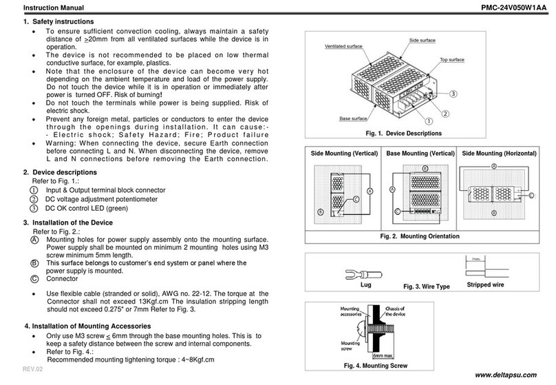
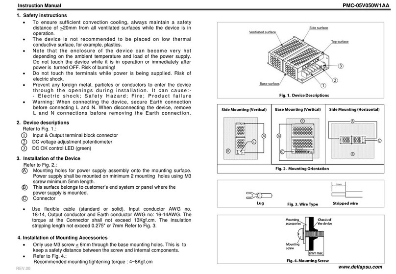
2. Device Descriptions
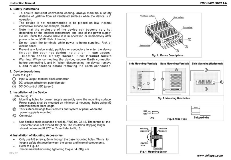
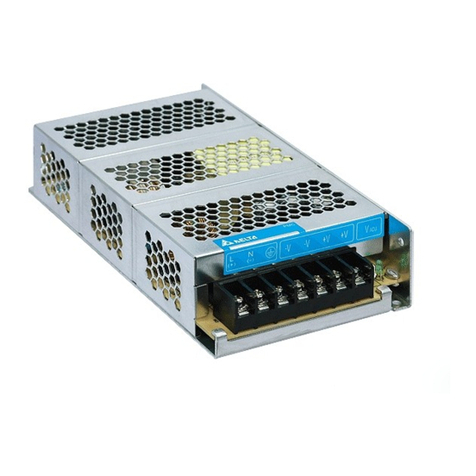
RefertoFig.1.:
䐟Input&Outputterminalblockconnector
䐠DCvoltageadjustmentpotentiometer(22V-28V)
䐡DCOKcontrolLED(Green)
3. Installation of the Device
RefertoFig.2.:
䑵Mountingholesforpowersupplyassemblyontothemountingsurface.Thepowersupply
shallbemountedonminimum2mountingholesusingM3screwminimum5mmlength.
䑶This surface belongs to customer’s end system or panel where the power supply is
mounted.
䑷Connector
• Useexiblecable(strandedorsolid)withthefollowingsizes:
• ThetorqueattheConnectorshallnotexceed13Kgf.cm.Theinsulationstrippinglength
shouldnotexceed0.275”or7mm(RefertoFig.3).
4. Installation of Mounting Accessories
RefertoFig.4.:
• OnlyuseM3screw≤6mmthroughthebasemountingholes.Thisistokeepasafety
distancebetweenthescrewandinternalcomponents.
• Recommendedmountingtighteningtorque:4~8Kgf.cm.
REV.00
Fig. 1. Device Descriptions
PMH-24V50WCAA (Standard Connector) PMH-24V50WCAJ (IP20 Connector)
PMH-24V50WCAL (Front Face Connector)
Fig. 3. Wire Type Fig. 4. Mounting Screw
Lug Stripped wire
Mounting
accessories
Mounting
screw
Chassis of
the device
6mm max.
7 mm
Fig. 2. Mounting Orientation
Side Mounting (Vertical) Base Mounting (Vertical) Side Mounting (Horizontal)
PMH-24V50WCAH (Harness Connector)
PMH-24V50WCAA PMH-24V50WCAJ PMH-24V50WCAL
AWG20-14 AWG20-12 AWG20-12
B
C
AA
C
B
B
C
A
3
1
Base surface
Top surface
Side surface
Ventilated surface
2
2
3
1
