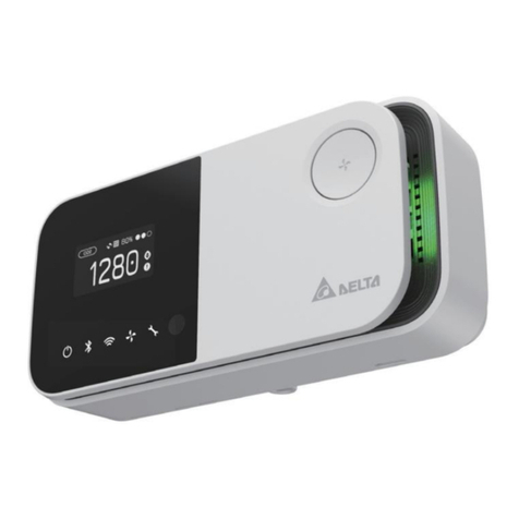
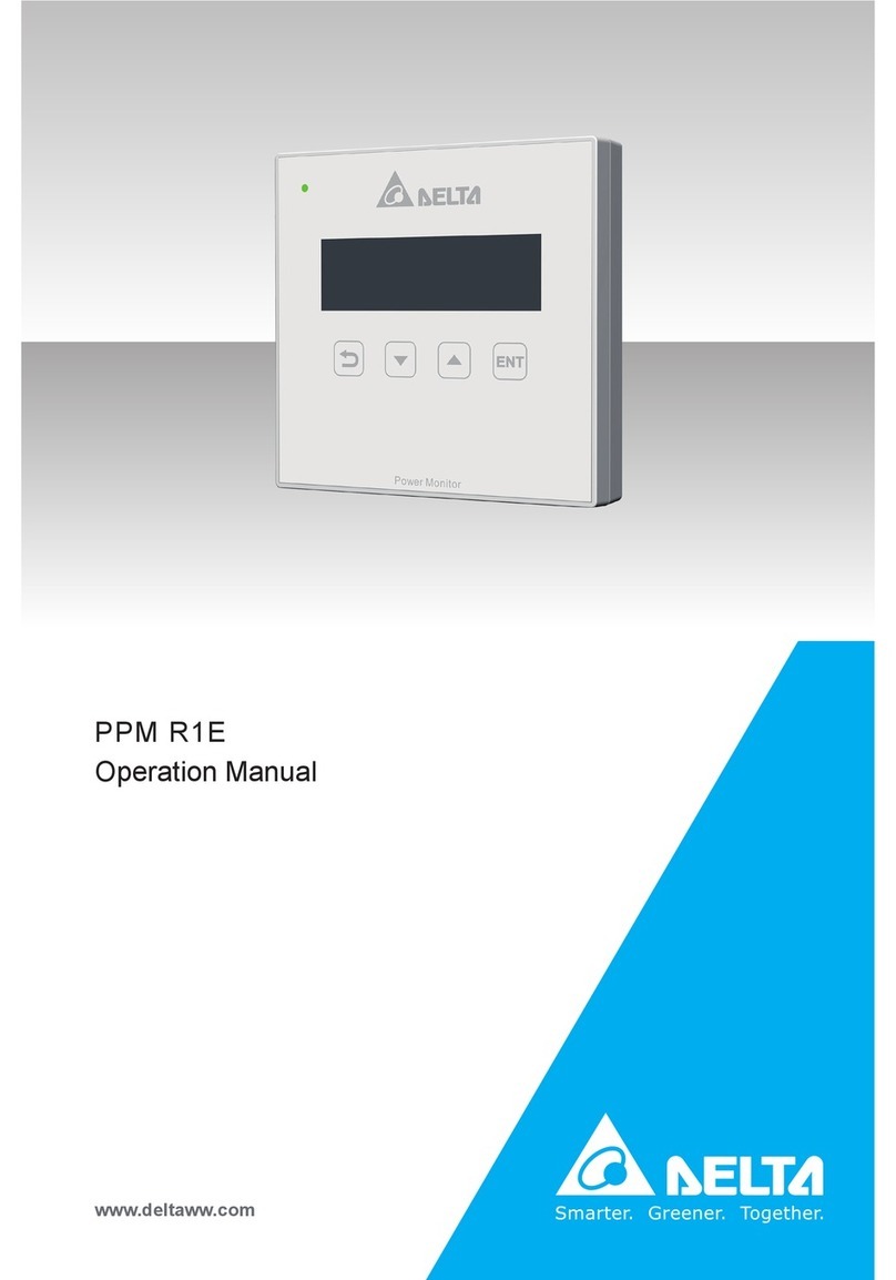
Delta R3E User manual

The power behind competitiveness
Delta Power Monitor
Installation Manual
R3E (for commercial use only.)
www.deltaww.com

2
Contents
■Introduction■
Precautions for Your Safety
Essential Points for Safety
Precautions for Use
1.Preparation before construction
1.1Scope of Delivery
1.2Dimension
1.3Descriptions and Functions of Parts and Components
2.Installation
2.1Installation order
2.2System Diagram
3.Setting
3.1Setting the Communications Unit
3.2Setting Power Monitor and Cable
4.Default Settings
4.1Connection
5.Installation Method
5.1Wall Installation
5.2Desktop Installation
5.3Wiring access
6.Description of the screen display
6.1Home Screen
6.2Operation Screens
6.3Reset Method
7.Service Mode
7.1Entering or Exiting Service Mode
7.2Exclusive Service Mode Functions
8.When Something Seems Wrong (Troubleshooting)
8.1Error Displays
8.2Troubleshooting
9.Specifications
9.1Power Monitor
03
05
06
08
09
10
11
12
13
15
16
19
20
20
21
24
25
26
27
40
42
43

3
This Installation Manual provides precautions with the following notations and symbols for safe
use of the Power Monitor (for commercial use only.) : R3E.
Precautions described herein contain important aspects of safety.
Please observe and follow these descriptions.
Notations and symbols are described below:
Notations for safe use of the product and their meanings
Precautions for Your Safety
Failing to handle the Product properly may result in the described danger
leading to slight or intermediate level injuries and in some cases may also
result in serious injury or death.
Failing to handle the Product properly may result in the described danger
leading to slight or intermediate level injuries or property damages in some
instances.
■ Explanation of graphic symbols
● Electric Shock Precaution
Notifications pertaining to precautions for potential electric shock,
under specific conditions
● General
Unspecified general notifications pertaining to prohibited actions.
● Disassembly prohibited
Notifications pertaining to prohibition of equipment disassembly,
when doing so can potentially lead to injuries such as electric shock.
● General
Unspecified general notifications pertaining to instructions for users
Warning
Caution
Introduction

4
Do not allow any fire producing objects to be near the Product, or apply any spray,
including combustible gases, to the Product. The Product may ignite or explode in
the unlikely event such an occurrence takes place.
Do not touch the Product with wet hands.
Power Monitor may cause injury due to electric shock or equipment malfunction may
occur in the unlikely event such an occurrence takes place.
Do not install the Product in a place that is subject to significant effects of vibration
and impact. There is danger of injury from the Product falling in some rare cases.
Do not install the Product in the following types of locations:
There is danger of burnout in some rare cases.
・
Locations that are exposed to rain water, such as outdoors or under eaves and the like.
・Locations that are exposed to steam or where the moisture level is 30 to 85% RH,
such as lavatories, changing rooms, work sites, kitchens and the like.
When installing the Power Monitor on a wall made of materials that are not wood,
be sure to acquire plastic anchors available on the market to secure the Wall
Surface/Desktop Mounting Plate on the wall surface. There is danger of injury from
the Product falling in some rare cases.
Warning
Caution
Do not disassemble or modify the Product.
Power Monitor may cause injury or fire due to electric shock in the unlikely event
such an occurrence takes place.
Introduction

5
Items described below must be followed as they are necessary to secure safety.
1. Request a specialist to dispose of the Product.
2. Pull 6-pin terminal off when any abnormality is detected like smoke, heat.
3. Do not install the Product in any place that is prevented from having air flow, such as inside
closets or under stairs.
4. Install the Product with the “DELTA” logo facing up when installing the Power Monitor on a wall.
When not installed on a wall, set the Product on the Wall Surface/Desktop Mounting Plate when
using the Product.
5. Take care to ensure no water or other liquid gets on the Power Monitor.
6. There is danger of injury. Do not throw the Product.
Essential Points for Safety
Introduction

6
1. The Product is not a specified measuring instrument that passed any certification criteria of any
designated accreditation organization as prescribed by the Measurement Act. The Product may
only be used to provide a rough indication on the amount of power.
3. The Product may malfunction or may be damaged by static electricity. Be sure to remove any
static electricity on the body, through such means as touching a metal object nearby, prior to
coming into contact with the Product.
2. A touch panel type liquid crystal display has been adopted for the Product. Do not press or hit
hard on the surface of the display.
4. Do not connect a telephone line or household LAN cable to the LAN terminal on the Power
Monitor. There is danger of the Product malfunctioning.
Precautions for Use
5. Reverting the date and time by at least a 15 minute interval into the past will result in the loss of
performance data. Set the date and time correctly.
Example : [A case where performance data is lost]
The time is inadvertently changed from 9:15 to 8:45 and then reverted to 9:15.
The performance data starting from 8:45 onwards are added to the performance data from 8:45
and the performance data for the period since 8:45 is lost. Lost data cannot be restored.
● Time is changed from 9:15 to 8:45.
● Time is changed from 8:45 to 9:15.
Example : [A case where performance data is not lost]
The time is inadvertently changed from 9:28 to 9:18 and then reverted to 9:28.
The performance data from 9:15 is fixed as of 9:30 and as such, the performance data is not lost,
as long as the time change does not extend to at least a 15 minute interval.
●Time is changed from 9:28 to 9:18.
● Time is changed from 9:18 to 9:28.
8:30 8:45 9:00 9:15 9:30
Data is added to that of 8:45.
Performance data is not lost.
Performance data is lost.
8:30 8:45 9:00 9:15 9:30
8:30 8:45 9:00 9:15 9:30 8:30 8:45 9:00 9:15 9:30
Introduction

7
6. Do not install the product in the following places:
・Do not expose to extreme fluctuation temperature.
・Do not expose to salt air.
・Do not expose to corrosive substances, explosive / flammable GAS, chemicals.
・Do not install in direct sunlight.
・Do not install in a place exceeding the operating temperature range (-20 to +50°C).
・Do not install above 2000m MSL or higher.
・Do not expose to water vapor, oil vapor, smoke, cotton dust, metal powder, sawdust, Warakuzu.
7. Store the Product in a location with the temperature ranging between -20 and +60°C, with the
humidity ranging from 30 to 85% RH.
8. For commercial use, the product can monitor maximum 32 inverters at one time.
9. If installed outdoor, please put it in box which is suitable for outdoor use.
Introduction

1.
Preparation before construction
1.1.Scope of Delivery
8
Verify that following items are available for use prior to using this feature.
No
1
2
3
4
1 unit
1 piece
2 pieces
Product name
Power Monitor
Wall Surface /
Desktop Mounting Plate
Wood screws (+) for Wall Surface /
Desktop Mounting Plate
(dia. 4 x 20 mm)
Shape Qty Remarks
This is a plate used to install
the Product on a wall or on a
desk.
These are wood screws for
the Wall Surface / Desktop
Mounting Plate.
Quick installation guide 1 copy
■ R3E
Preparation before construction

9
190mm
120mm
32mm
25mm
35mm
58mm
40mm
■ 7-inch Power Monitor
■ Wall Surface / Desktop Mounting Plate
POWERMONITOR
1.2.Dimension
Preparation before construction

10
1.3.Descriptions and Functions of Parts and Components
POWERMONITOR
■ Power Monitor
Important
Do not connect a telephone line to the LAN terminal.
①LAN terminal (RJ-45 terminal) (fitted with a protective cover)
This is the terminal that is used to connect the system to an internet line. (A setup is required.)
②RS-485 (a 6-pin connect)
This is the connect that is used to connect a 6-pin connector provided, to link the supply of power
and signals from the Inverter.
③Power Supply terminal (fitted with a protective cover)
Not used.
④USB Terminal (for USB 1 and USB 2) (fitted with a protective cover)
Downloading of various data and upgrading of software versions can be performed.
* Customers are requested to procure their own USB memory and USB cable.
⑤Insertion slot for anchoring the Wall Surface Mounting Plate.
This is the insertion slot used to install the Wall Surface / Desktop Mounting Plate when installing
the Product on the wall.
⑥Insertion slot for anchoring the Desktop Mounting Plate
This is the insertion slot used to install the Wall Surface/ Desktop Mounting Plate when installing
the Product on desktop.
⑦Reset button
Restart the Power Monitor. The settings and records will not be deleted.
⑧Wiring access
According to the prescribed wiring method, remove the tab on the wiring access, and guide the
cable through.
⑨Touch Panel section
Displays are switched and various settings are performed by performing touch panel operations.
⑩ Screw hole
For fixing screw of 6-pin terminal.
USB 1
USB 2
CAN-L
CAN-H
RS485-B
RS485-A
GND
+12V
LAN
DC 12V
①
②
③
④
⑥⑤⑦
⑩
⑨ ⑧
⑧
Front Back Side
Preparation before construction

11
2.Installation
2.1.Installation order
「1.Setting」
One Point
・Please set connection ID before connect to the Inverters.
The ID of inverters must be different.
・The ID range is 1~32.
「2.Default Settings」
「3.Installation Method」
Installation

12
2.2.System Diagram
■ Connection example
There are different power distribution methods and connected positions between each inverter model,
please check the inverter Operation and Installation Manuals.
PV Panel
Inverter
Inverter 2 Inverter 3
Power Monitor
Communication
connector
Communication
connector
Distribution box / Switchboard
(The connections are same for other inverters.)
6PIN connector
L1
+ − + − + − + −
L2
L3
ON ON ON
1
ON
1
Terminal
switch
RS485-B
RS485-A
GND
+12V
Installation

■Using 1 inverter
(1) Remove the communications connectors from the inverter, and thread the cables through the
waterproof gasket.
※If the removal method is unclear, see the inverter Operation and Installation Manuals.
(2) Hold down the top of the terminal block on the communications connectors, and insert the cables
as follows: 1 VCC, 2 GND, 3 DATA+, 4 Data-.
Check that the cables have been inserted securely.
■Cables
・Make sure to use RS-485 cables.
Prepare 0.3 to 0.5mm2x single wire, 4 cores (twin wires rather than 2 pair) shielded cables
(rated temperature: 80ºC to 85ºC).
・Read the inverter Operation and Installation Manuals while working.
・
If connecting multiple inverters, complete the settings so that there are no duplicate IDs.
・Process the cables before use.
Recommended cable: FCPEV-NC 0.65mm
(3)Turn ON the DIP switch on the communications director.
13
8mm
Cable
40mm
Φ 0.6~0.8 Φ 5~6
ON
1
To the Power Monitor
3.Setting
3.1.Setting the Communications Unit
Setting

■ Using 2 or more inverters
(1) Remove the communications connectors from the inverter, and thread the cables through the
waterproof gasket.
(2) Hold down the top of the terminal block on the communications connectors, and insert the
cables connected to the Power Monitor as follows: 3 DATA+, 4 Data-.
(3) Next, insert the cables into the adjacent inverter as follows: 5 Data+, 6 Data-.
Check that the cables have been inserted securely.
(4) Next, insert the aforementioned cables into the adjacent inverter as follows: 3 Data+, 4 Data-.
(5) Connect all VCC to VCC, and all GND to GND.
(6)
Make sure that the voltage between VCC and GND is in operating voltage range, and connect to
VCC and GND of Power Monitor.
(7)
Operating voltage range of Power Monitor is 10Vdc ~ 16Vdc, and rated operating voltage is 12Vdc.
■ Distance limitation
The power line between monitor and inverter is max 100m, and the communication line
between monitor and the last inverter is max 500m.
If monitor connects with Pyrheliometer/Thermometer, the communication line between monitor
and Pyrheliometer/Thermometer is max 500m.
(8)After completing the connection, turn ON the terminal switch for only the inverter that is
farthest from the monitor, and set all the other inverters to 1 (OFF).
14
To the
Power Monitor
ON ON ON
1
Communications
connector
Communications
connector
Communications
connector
Inverter2Inverter 3Inverter1
Terminal switch
inverter
with furthest
connection from
the Power Monitor
ON
1
Factory
default
ON
1
Set to ON
ON
1
Set to ON
POWERMONITOR
Inverter Inverter Inverter Inverter
Power Monitor
100m
500m
Communication
Power supply
Setting

15
・Process the cables before use.
・Creating 6-pin connectors
Hold down the enclosed 6-pin connector ①, and insert the cable.
・Connecting the main unit and the 6-pin connectors
(1)Insert the 6-pin connector into the main unit.
(2)
Pass a screwdriver through the screw hole, and tighten the two screws for the 6-pin connector.
(3)When all the wiring is complete, install the Power Monitor in its installation site.
When the connectors are complete, connect to the main unit.
8mm
Cable
40mm
Φ0.6~0.8 Φ5~6
①
Screw hole
Screw hole
■Under-wiring■Over-wiring
3.2.Setting Power Monitor and Cable
Setting

(3)When monitor shows time setting, please set up time.
16
4.Default Settings
4.1.Connection
接続設定開始画面
connection setting start screen
Time settings screen (Date and time shown are examples.)
(1)After started up, please choose language.
Language selection screen
(2)When monitor shows connection is started, please click [YES].
Default Settings

Touch the [Submit] button on the time selection screen. The time change dialog box will
be displayed.
Check the time, and touch the [Yes] button.
The time change dialog box will disappear, and the time change confirmation dialog box
will be displayed. Touch the [Yes] button once again.
時刻変更ダイアログTime change dialog box
再度時刻変更ダイアログ
Time change confirmation dialog box
17
Select the date frame. The date selection screen will be displayed.
Select the date that you want to set.
Touch the time frame for the time. The time selection screen will be
displayed. Select the time that you want to set.
日付選択画面Date selection screen
時刻選択画面Time selection screen
Default Settings

(5)When ID selection is done, the reconfirm screen will be displayed.
If change is needed, please click [Reconfigure].
If selection is correct, please click [Save], then monitor will show main page.
18
Reconfirmation screen connection setting complete screen
(6)When the settings are complete, the "Home screen" will be displayed.
As processing is implemented immediately after the settings are made, a " " icon is
displayed, so check the following details 1 to 3 mins later.
・Check that the " " icon is not displayed on the home screen.
・Check that the values for the power production icon have changed.
・Check the connection setting and connection log.
※If making the connection setting again, switch to service mode.
For service mode, see "7.Service Mode" (page 26).
(4)When time setting is done, monitor will show connection set up page.
Please select inverter ID and click [Save].
接続設定画面connection setting screen
Default Settings

19
50mm
50mm
150mm
20mm
■ Separation distance from respective surfaces of
main unit
■ Installing Wall Surface / Desktop Mounting Plate on Power Monitor
Wood screws, 4 dia
①
②
③
The Power Monitor may be mounted on a desktop or on a wall surface for use.
“Wall Installation”, “Desktop Installation” and “Wiring access” are respectively explained in this chapter.
* Consult the retailer where you purchased the Power Monitor when relocating your Power Monitor.
5.Installation Method
5.1.Wall Installation
● Installation on wall
① Install the Wall Surface / Desktop Mounting Plate
on the wall, using the wood screws provided.
・Install the Wall Surface / Desktop Mounting Plate on a location
that can withstand the weight of the main unit.
・Use countersunk screws of 4 dia., when installing at a location
where the provided wood screws cannot be used.
・
Apply torque of 1.5 to 2.0 Nm when installing wood screws on a wall made of wooden materials.
・Install on a flat wall surface.
② Verify the hooking portion of the Wall Surface / Desktop Mounting Plate and the Wall Mounting
Plate and the insertion slot for anchoring the Wall Surface Mounting Plate on the reverse surface
of the main unit, then press on the main unit until the insertion slot for anchoring is positioned
above the upper section of the Wall Surface / Desktop Mounting Plate.
③ Slide the main unit lower in that position and securely engage the hooking portion.
・
Hook on the insertion slot for anchoring the Wall Surface Mounting Plate on the reverse surface
of the main unit on the Wall Surface / Desktop Mounting Plate and shift down by approximately
1 centimeter.
36.7mm
25mm
35mm
23.3mm
74mm
40mm
■Dimensions of Wall Surface / Desktop Mounting Plate
and the main unit
Main unit
Installation Method

20
● Desktop installation method
① Insert the Wall Surface / Desktop Mounting Plate in the insertion slot for anchoring the Desktop
Mounting Plate at the lower section of the main unit, being careful about the direction the plate
is facing.
② Verify to ensure that there is no gap between the Wall Surface / Desktop Mounting Plate and
Part A at the bottom of the main unit, as shown in the figure to the right.
①
②A
5.2.Desktop Installation
5.3. Wiring access
③
③
① Remove the tab on the wiring access, using a pair of pliers or the similar tool.
(Remove burr with a pair of pliers to ensure that the cables are not scratched.)
② Pass a screwdriver through the screw hole, and tighten the two screws for the 6 pin connector.
③ When all the wiring is complete, install the Power Monitor in its installation site.
●
There are two wiring accesses in the upper and lower sections on the reverse side of the Power Monitor.
According to the prescribed wiring method, remove the tab on the wiring access, and guide the cable
through.
■When wiring from
bottom
■When wiring from top
②
Screw hole
Screw hole
①
①
Installation Method
Table of contents
Other Delta Monitor manuals

Delta
Delta TV-908A User manual

Delta
Delta DOP-107H Series User manual

Delta
Delta VMT-271 User manual

Delta
Delta Vivitek NovoTouch EK860i User manual

Delta
Delta PPM R1E Installation manual

Delta
Delta uno next User manual

Delta
Delta UNO-C07X011 User manual

Delta
Delta IIYAMA-X2783HSU-B3 User manual

Delta
Delta DOP-100 Series User manual

Delta
Delta DOP-110CS User manual

Delta
Delta TP70P User manual

Delta
Delta Vivitek NovoDisplay DK430 User manual

Delta
Delta VMT-221IP User manual

Delta
Delta DOP-107BV User manual

Delta
Delta DOP-103BQ User manual

Delta
Delta DOP-107EV User manual

Delta
Delta UNOlite User manual

Delta
Delta VMT-173 User manual

Delta
Delta DOP-103BQ User manual

Delta
Delta Vivitek NovoTouch EK650i User manual