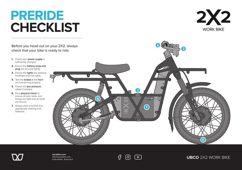
DEMA GRITCH 7 User manual

Cerficate of warranty
Bicycle operaon and maintenance manual
Garanezerfikat
Fahrrad Bedienungs- und Wartungshandbuch
Záručný list
Návod na obsluhu a údržbu bicykla
Záruční list
Návod na obsluhu a údržbu jízdního kola
Garancialevél
Használa és karbantartási útmutató a kerékpárhoz
Karta gwarancyjna
Instrukcja obsługi i konserwacji roweru
Garancijski cerficat
Delovanje in navodila za vzdrževanje koles
Jamstveni list
Upute za korištenje bicikla

3 - 22
23 - 43
44 - 63
64 - 83
84 - 104
105 - 125
126 - 144
145 - 162
Bicycle operaon and maintenance manual
Fahrrad Bedienungs und Wartungshandbuch
Návod na obsluhu a údržbu bicykla
Návod na obsluhu a údržbu jízdního kola
Használa és karbantartási útmutató a kerékpárhoz
Instrukcja obsługi i konserwacji roweru
Delovanje in navodila za vzdrževanje koles
Upute za korištenje bicikla
EN
DE
SK
CZ
HU
PL
SI
HR

Dear customer!
Thank you for your trust and purchase of a DEMA brand bicycle. DEMA is a Slovak bicycle
brand that has a registered and protected trademark. This guide will help you setup and main-
tain your bicycle so it serves to your sasfacon as long as possible. This guide will also explain
warranty terms and serves as a cercate of warranty as well. Also, please note that the seller
must provide a complete pre-sale bicycle servicing. The manufacturer is not liable for any
injury caused by inadequate Pre-sale service, improper maintenance or misuse.
We wish you many happy kilometres!
DEMA Senica, a.s.
manufacturer
Content
Overview
Bicycle types
Bicycle preparaon for the ride
Folding bicycle service
Safe riding recommendaons
Permissible weight of the rider and luggage - recommendaons
Bicycle maintenance
Tools for assembly and maintenance
Assembly and disassembly of the wheels
The braking system
Gears
Head set, stem, handlebar, seat post and the saddle
BB set, crank set and pedals
Wheels, hubs, res and training wheels
Suspension
Racks
Cleaning and lubricaon
Maintenance schedule
Warranty
Translaons of important warning labels appearing on the DEMA bicycles
1.
1.1
1.2
1.3
1.4
1.5
2.
2.1
2.2
2.3
2.4
2.5
2.6
2.7
2.8
2.9
3.
4.
5.
6.
Bicycle operaon and maintenance manual EN 3

1. Overview
1.1 Bicycle types
According to their use bicycles can be divided into mountain, cross, tour, city and racing bi-
cycles. According to their size bicycles are classied as children’s bicycles and bicycles for
adults (including junior’s versions). Children’s bicycles must meet the condion of a maximum
seat height greater than 435 mm and lower than 635 mm. The bicycles for adults (including
junior’s versions) must meet the condion of a maximum seat height greater than 635 mm.
Mountain bicycle (MTB)
It is designed for driving o paved roads and is equipped with wider res with a more robust
tread paern for easy passing of rough terrain. The most commonly used wheels with dia-
meters of 20, 24, 26, 27.5 or 29 inches and 11 to 30 speeds allow handling in even the most
dicult terrain. Classic hard tail mountain bike has only front suspension, usually from 80
mm to 120 mm. In contrast to this type of mountain bike, the full-suspension bicycle also has
suspension in the rear part. However, it sll belongs to the same bicycle category. Mountain
bikes must meet property requirements set out in the EN ISO 4210 norm in force.
Cross and Tour bicycles (Cross, Touring)
Cross and Tour bikes mostly use wheels with a diameter of 28 inches and are known as the
most suitable bicycles for cycling tourism because they combine the advantages of road bi-
cycles with the advantages of mountain bike - they allow a fast ride on asphalt roads, but you
can also use them in easy terrain. Tour bicycles are usually compared with o-road bicycles
with addionally ed lighng, fenders and racks. Some models of tour bicycles are equipped
with suspension forks. This category usually has 18 to 30 speeds. Cross bicycles must meet
requirements of the STN EN 14766 norm in force. Tour bicycles must meet requirements of
the EN ISO 4210 norm in force.
City bicycle (CTB)
City bicycles are designed for riding on the roads. They are of a simple build, mostly equipped
with lighng, fenders and racks. They use wheels with diameters of 20, 24, 26 or 28 inches.
They can be equipped with a mul-speed gearbox, which is hidden in the rear wheel hub, or a
tradional rear derailleur. The number of speeds ranges from 1 to 24. This category includes
also folding bicycles. City bikes must meet requirements of the EN ISO 4210 norm in force.
Racing bicycle (Road)
It is designed for fast riding on asphalt roads. These bicycles use narrow res, occasionally
tubeless res that have a low rolling resistance and permit higher speeds. This category usu-
ally has 18 to 30 speeds. Racing bicycles must comply with requirements of the EN ISO 4210
norm in force.
Fitness bicycle
This bicycle is designed for riding on asphalt roads. Unlike in road bicycles, it has handlebars,
brake levers and shiers of a Tour bicycle. Fitness bicycles must comply with requirements of
the EN ISO 4210 norm in force.
Freestyle bicycle
The Freestyle bike is designed to run on the ground. It has a durable frame, wheels with a
diameter of 26 cm and is suitable for aggressive driving. It is intended for driving the terrain
through various obstacles, it has various ulies, extended axes for various acrobacs.
BMX
BMX is designed for eld trips. It is used for driving in special parks, based on a 20-inch dia-
meter wheel, rigid and durable frame and fork. BMX wheels must meet the requirements of
EN 16054 cat 2.
EN4Bicycle operaon and maintenance manual

Kids bicycle
Children‘s bicycles are designed to ride on asphalt roads and easy terrain. Dierent sizes
and frame diameters correspond to dierent age groups (12, 14 or 16 in.). Usually they are
equipped with auxiliary wheels. When choosing the right size of a wheel, it is necessary to ta-
ke into account the height and abilies of the child. Children‘s wheels must meet the require-
ments of the applicable EN ISO 8098 standard.
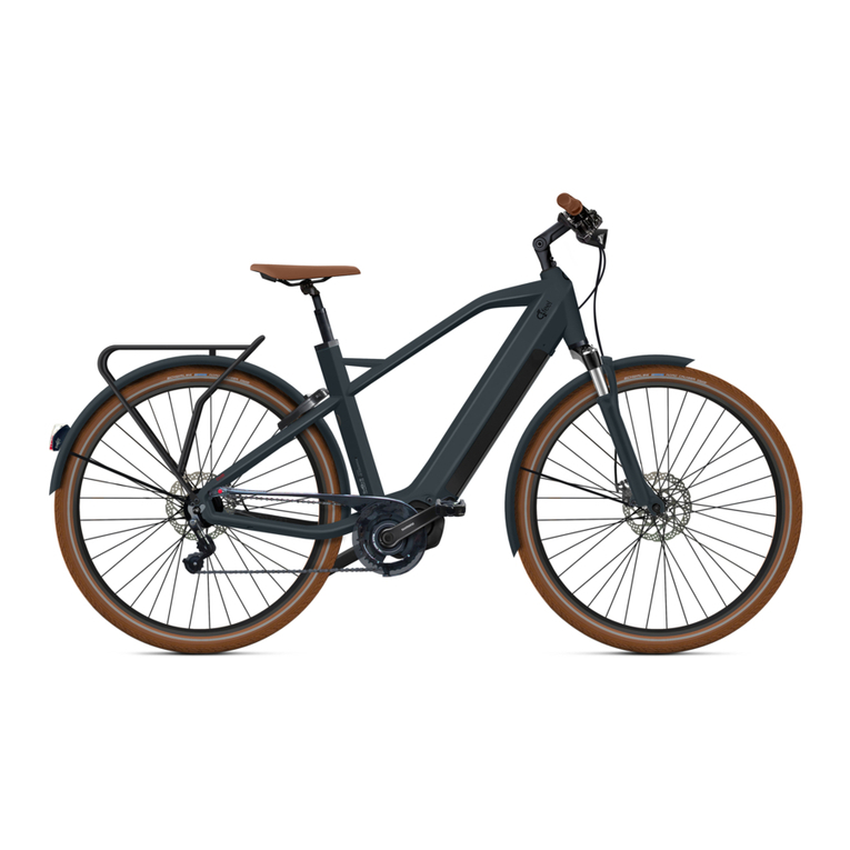
E-bike
E-bike meets the requirements of European standards EN 15194 and EN 4210-2, thus falls
into category EPAC (Electrically Power Assisted Cycle = „bicycle with auxiliary electric propul-
sion“). In terms of the law on road trac, EPAC is considered to be normal bicycle and driving
license is not required. Maximum connuous rated motor output for EPAC E-bikes is limited
to 250W. Propulsion is acvated by pedalling, where the motor assistance is cut o when the
cyclist stops pedalling and is otherwise progressively reduced and nally cut o before the
E-bike speed reaches 25 km/h.
1.2 Operang instrucons
Saddle and seat post
The saddle should be set in a horizontal posion. If it is not in this posion, loosen the seat
post lock, set the saddle to a horizontal posion and ghten the seat post lock. Saddle height
is properly adjusted when the crank is parallel to the seat tube, while the heel is placed on
the rear edge of the pedal, and the cranks are turned so that the pedal with your heel is at the
lowest posion.In this posion, your leg should be slightly bent at the knee. If not, loosen the
seat clamp bolt, or the quick-release lock, and adjust the seat post height by pulling or pushing
the seat post. Subsequently ghten the seat clamp bolt or the quick-release lock so that it is
not possible to move the seat post. The minimum inseron depth for the seat post into the
frame is marked on the seat post. The wording of this indicaon may vary by manufacturer of
the seat post (e.g. MIN, STOP, MAX, etc.).
Please note that you can use the seat post pulled out to the mark, which clearly indicates
the minimum depth of inseron of the seat post into the frame!
Quill stem
There is a mark on the quill stem that indicates the minimum depth of inseron of the stem
into the fork steerer. The wording of this indicaon may vary by the manufacturer of the stem
(e.g. MIN, STOP, MAX, etc.).
Please note that you can use the stem pulled out to the mark that clearly indicates the
minimum depth of inseron of the stem into the fork steerer!
Bicycle operaon and maintenance manual EN 5

Brakes
The le brake lever controls the front brake; the right brake lever controls the rear brake.
We recommend checking the ghtness of all joints, xing of the wheels, funconality of the
brakes and possible mechanical damage of the frame and components.
We recommend checking the ghtness of all joints, xing of the wheels, funconality of the
brakes and possible mechanical damage of the frame and components.
1.3 Folding bicycle service
Unfolding
1. Folded frame of the bicycles unfold and sele to the straight posion. Push lock lever to the
frame and secure the security lock.
2. Unfold folded handlebar column to upright posion. Secure handlebar column joint with
pushing quick release lever to the very column. Lock the lever with the security lock.
3. Pull seatpost and secure it in required posion with quick release lever.
4. Adjust height of telescopic stem.
5. Unfold pedals.
6. Do not forget to fold kickstand before the ride.
Folding
Put a bicycle on kickstand.
1. Release quick release lever on seatpost and insert the saddle to the boom end. Boom
part of seatpost serves as a lean point of folded bicycle.
2. Release quick release lever on handlebar column and insert it to the boom end.
3. Release security lock on locking mechanism of folding handlebar column. Release folding
system lever and fold handlebar column down to front wheel.
4. Fold both pedals. Fold kickstand. Take the posion on the right side of the bicycle. Release
security lock. By the le hand grab main frame folding mechanism lever, by the right hand
grab front fork of the bicycle. Release the lever by le hand, pull up front fork (wheel) by
right hand and fold front part of the frame to the rear part of the frame. Beware of any injury
on your health or damages of your clothes during folding the bicycle.
EN6Bicycle operaon and maintenance manual

1.4 Recommendaons for safe riding
For riding on public roads your bicycle must be equipped with accessories and equipment in
accordance with the legislaon in force dening the condions of vehicle trac on roads. It
is necessary to comply with the road code when cycling on roads. The bicycle that you have
purchased has passed a comprehensive Pre-sale service, as evidenced by the record in the
warranty book. However, we also recommend that aer driving for about 80km, or aer 1
month following the purchase of the bicycle at latest, you come to the seller or to a specialized
workshop for the rst service inspecon. In the course of ordinary maintenance, which the
bicycle requires, please follow the instrucons in this manual. In the case of more dicult
operaons, we recommend you seek help of a professional workshop. Children’s bicycles are
designed to travel on asphalt roads or in light terrain under the supervision of a responsible
adult. It is essenal that parents or other responsible persons properly instruct the children
about bicycle use, correct riding technique, the funcon of the brakes and how to brake.
As a manufacturer of bicycles we recommend the use of a helmet in accordance with legislaon
in force on every ride and also for safety reasons we strongly recommend the use of helmets on
o -road rides. We also recommend using footwear and clothing appropriate for cycling.
1.5 Recommendaons for the permissible weight of the rider and luggage
Manufacturer-recommended permissible weights of the rider with luggage are:
- 25 kg for children’s bicycles
- 70 for BMX bicycles
- 100 kg for folding bicycles
- 110 kg for mountain, cross, tour, city, racing, freestyle bicycles
- 120 kg for e-bikes
The maximum total weight is calculated as the sum of the weight of your bicycle and the
recommended permissible weight of the rider with luggage for your bicycle.
Follow the recommended permissible load of the bicycle and never overload the bicycle!
2. Bicycle maintenance
2.1 Tools for assembly and maintenance
The list of tools needed for basic assembly and maintenance:
- at and Phillips screwdrivers
- spanner 8mm, 9mm, 10mm, 13 mm thin type, 15mm, and 17mm
- combinaon pliers
- cable cung pliers
- allen wrenches: 2.5mm, 3mm, 4mm, 5mm, 6mm, 8mm, and 9mm
- removal tools for cranks
- removal tool for sprocket / cassee
- bent ring wrench 14 mm or 15 mm
- head assembly wrenches: 30mm, 32mm, 36mm
- re repair kit, re levers, re pump
- chain wear gauge
Bicycle operaon and maintenance manual EN 7

During assembly and maintenance of the bicycle follow the maximum ghtening torques re-
commended by the manufacturer of the bicycle listed in the table on page 164. If there are
lower torque limits marked on the components by the manufacturer, follow these torques.
We recommend using only genuine replacement parts that you purchase from authorized
dealers.
2.2 Mounng and dismounng of wheels
The wheel may be released and subsequently fall out of the fork when riding with insu-
ciently ghtened quick-release locks or nuts, which can result in damage to the bicycle or
injury or death to the rider.
Dismounng the front wheel
Put the quick-release lock lever into the open posion (OPEN). Subsequently loosen the
coupling nut by a few turns so that the wheel can be pulled out of the fork. In case of the
v-brakes use, loosen the cable.
Mounng the front wheel
Lay the wheel with the open quick-release lock on the le side on the oor and carefully
mount the front fork on the wheel axis. Make sure the wheel is properly mounted and centred
in the fork. Tighten the nut on the quick-release lock a few turns and push the lever toward
the fork into the closed posion (CLOSE). When the nuts of the quick-release lock are proper-
ly ghtened the lever must provide a slight resistance and the clamping mechanism must press
the fork dropouts. Apply a ghtening torque of 10-12 Nm.
Dismounng the rear wheel
In case of the v-brakes use, loosen the cable. Set the rear derailleur and chain to the smallest
sprocket wheel. Put the quick-release lock lever into the open posion (OPEN). Then loosen
the coupling nut a few turns so that it is possible to pull the wheel out of the frame. Li the
rear of the bicycle frame while pushing the wheel forwards and downwards unl the wheel
axle gets out of the frame.
Mounng of the rear wheel
Set the rear derailleur to the posion of the smallest sprocket wheel. Set the quick-release
lock lever into the open posion (OPEN), so that the lever is on the opposite side of the wheel
as the sprocket. Push the rear derailleur backwards and aach the chain to the top of the
smallest sprocket wheel. Subsequently aach the wheel to the frame. Make sure the wheel is
properly mounted and centred in the frame. Tighten the nut on the quick-release lock a few
turns and push the lever toward the frame into the closed posion (CLOSE). When the nuts of
the quick-release lock are properly ghtened the lever must provide a slight resistance and the
clamping mechanism must press the frame dropouts. Apply a ghtening torque of 10-12 Nmv.
If you are using disc brakes, never push the brake lever if the disc is not in the calliper, because
the seng of the brake pads will change and it will not be possible to mount the wheel with
the disc. Aer every mounng and dismounng of the wheels, check the proper operaon of
the brakes!
CLOSE
OPEN
EN8Bicycle operaon and maintenance manual

2.3 Brake System
Check the brake system and the proper operaon of the brakes before each ride. If the brakes
are not working properly or some parts are damaged or worn, do not use the bicycle and seek
out a specialised workshop.
The brake system consists of:
- brake levers
- brake lines
- brake shoes (brake callipers)
- rims or brake discs
Brake Levers
The brake levers must always be rmly aached to the handlebar in such a posion as to be
within easy reach.
Brake lines
Brake lines are divided into two types:
- mechanical brake lines that consist of Bowden cables and wires
- hydraulic brake lines that consist of hoses and hydraulic uid
Inspecon and maintenance of brake lines
Regularly check the condion of Bowden cables, brake wires and hydraulic brake hoses. Wires
must move freely in the Bowden cable, must not be rusty, frayed or otherwise damaged.
Always secure the wire end with end caps ng for them. Bowden cables and hydraulic ho-
ses must not be broken or cracked. If you nd any faults in the brake system, do not use the
bicycle and seek out a specialized workshop.
The most commonly used types of brakes:
- type „V” rim brakes
- rim brakes for road racing bicycles
- disc brakes (mechanical and hydraulic)
- coaster brakes
Type „V“ rim brakes
Brakes must be ghtened to the V-brake pivots on the frame or fork and must be properly
centred. If the brake blocks are distanced more than 3-4 mm from the rim, the brake wire was
pulled out or brake shoes are worn out, and the brake needs to be reset, or the brake blocks
need to be replaced. To set the brake wires use the adjustment screws that are located on
the brake lever. Ihe brake wire is very loose and the adjustment screws are not sucient for
V-brake Rim brake Disc brake
Bicycle operaon and maintenance manual EN 9

proper adjustment, return the screws to their default posion and ensure correct wire tension
following way. Loosen the fastening screw on the brake and tense the cable by pulling it. Then
ghten the fastening screw.
Rim brakes for road racing bicycles
The brakes for road racing bicycles are set in a similar manner as the type „V” rim brakes.
Regularly check the condion of the rim‘s braking surface. In case of wear have them changed
in a specialized workshop.
Checking wear:
Some rims have a measuring groove or dot - when the braking surface of the rim becomes
so thin that these checking characters disappear, it is necessary to replace the rims. Rims
which are not equipped with the above-menoned checking indicaons must be replaced if
the deecon of the braking surface of the rim is more than 0.3 mm from the original plane
shape of the brake surface, above the original plane of the brake shoes or the wall thickness
is less than 1.1mm.
Disc brakes
This type of brakes is one of the most eecve. Disc brakes are divided into mechanical
and hydraulic disc brakes. Mechanical disc brakes are controlled by a wire and hydraulic disc
brakes are controlled by liquid.
Inspecon and maintenance of disc brakes
Always keep the brake discs clean. Do not touch the braking surface with bare hands and
make sure that the braking surface does not come into contact with any grease to prevent
reducon in braking eciency. If the discs or brake pads come into contact with grease or
brake uid, they must be thoroughly cleaned and, possibly, the brake pads should be replaced.
For cleaning use special products intended for this purpose. Regularly check the condion of
discs and brake pads. If the discs or brake pads are damaged or worn, replace them with new
ones. Never push the brake lever if the disc is not in the calliper, because the seng of the
brake pads will change and it will not be possible to mount the wheel with the disc. When
replacing the brake uid, always use the type of brake uid determined by the manufacturer
of the disc brake. If the thickness of the disc’s braking surface reaches the minimum thickness
prescribed by the manufacturer, the disc should be replaced. This value is indicated on the
body of the disc. If you encounter any of these problems, do not use the bicycle and seek out
a specialized service.
Coaster brakes
If the rear brake is designed as a coaster brake (so-called „Torpedo brake”), engage it using
force exerted by the foot on the pedal in the backwards direcon. The brake mechanism
must operate independently of any posion or seng of the drive mechanism. The dierence
between the posion of the crank during riding and braking may not exceed 60°. The Coaster
brake does not require any special maintenance, an annual check and oiling is sucient.
EN10 Bicycle operaon and maintenance manual

When driving on wet roads or a humid environment during rain the braking distance may increase.
2.4 Gears
The transmission system consists of the following parts:
- shiers
- rear derailleur and front derailleur
- transmission cables
- chain
Shiers
You may nd several types of shiers on DEMA bicycles:
- Shimano Dual Control
- lever shiers
- grip shi shiers
The right shier shis the chain on the sprocket using the rear derailleur. The le shier shis
the chain on the chainrings using the front derailleur.
A correctly set up transmission system should operate precisely and almost noiselessly. If the
shiing of gears is slow or problemac, it is necessary to adjust the transmission system. The
rear derailleur must be properly set rst and subsequently the front derailleur. Shiers must
always be rmly aached to the handlebar and posioned for ease of reach.
Rear derailleur
Set the rear derailleur and chain to the smallest sprocket. Aer that check whether the smal-
lest sprocket, both rear derailleur pulleys and chain are in a straight line. If this is not the case,
you need to set correctly the rear derailleur, and possibly straighten the rear derailleur hanger.
The limits must be correctly set for proper operaon of the rear derailleur. The limits are set
by two limit adjusng screws located on the rear derailleur.
Shimano
Dual Control
road
Lever shier Grid shi shier
Bicycle operaon and maintenance manual EN 11

Adjusng the lower limit of the rear derailleur
Set the chain on the smallest sprocket and the biggest chainring and loosen the transmission
wire fastening screw. Set the smallest sprocket, both rear derailleur pulleys and chain in a
straight line using the limit adjusng screw marked by the leer „H”. Pull the transmission wire
and ghten the transmission wire’s fastening screw.
Adjusng the upper limit of the rear derailleur
Set the chain on the biggest sprocket and the smallest chainring. Set the biggest sprocket,
both rear derailleur pulleys and chain in one line using the limit adjusng screw marked by
the leer „L”.
Front derailleur
Make sure that the outer chain guide plate is parallel to the chainrings. The lower edge of the
outer plate must be 2-3 mm above the teeth of the biggest chainring. The limits must be cor-
rectly set for proper operaon of the front derailleur. The limits are set by two limit adjusng
screws located on the front derailleur.
Adjusng the lower limit of the front derailleur
Set the chain on the smallest chainring and the biggest sprocket and loosen the transmission
wire fastening screw. Tighten the limit adjusng screw marked by the leer „L” so that the
chain is 1-2 mm away from the inner chain guide plate. Pull the transmission wire and ghten
the transmission wire’s fastening screw.
Adjusng the upper limit of the front derailleur
Set the chain on the biggest chainring and the smallest sprocket. Tighten the limit adjusng
limit adjusng bolts mounng bolt hanger
mounng
mounng bolt
gear cable
limit adjusng bolts clamp
chain guide
EN12 Bicycle operaon and maintenance manual

screw marked by the leer „H” so that the chain is distanced approximately 1 mm away from
the outer chain guide plate.
Inspecon and maintenance of shiing cables
To adjust the shiing wires, use the set screws that are located on the shiers. You can also
use the adjustment screw that is located directly on the rear derailleur. If the shiing wire
is very loose and the adjustment screws are insucient for proper adjustment, return the
adjustment screws to their default posion and ensure the correct wire tension this way.
Loose the fastening screw and tense the wire by pulling. Then ghten the fastening screw.
Regularly check the condion of the shi ing wires and Bowden cables. Wires must move freely
in the Bowden cable, they may not be rusty, frayed or otherwise damaged. Always secure the
wire ends with end caps ng for them. Bowden cables must not be broken or cracked. If a fault
is found, do not use the bicycle and visit a specialised workshop.
Chain
The chain is among the most stressed parts of the bicycle, so it is necessary to pay aenon
to its maintenance. Keep the chain clean and treat it using manufacturer-recommend products
for chains. Make sure that the chain is always properly tensioned. If the bicycle is equipped
with a rear derailleur, it will directly ensure proper chain tension. For bicycles without a rear
derailleur, set the chain tension by correct moving and posioning of the rear wheel in the
frame dropouts. To check the chain wear, use a calibrated gauge. In case the chain is worn
make sure to change it for a new one, so that it does not damage other parts of the transmis-
sion system.
2.5 Headset, stem, handlebar, seat post, saddle
Headset
Used types of headsets:
1. Threaded headset
2. Threadless headset (Ahead)
The headset consists of a set of bearings and accessories which allow the handlebar, stem and
fork to rotate in the frame. The headset may loosen by the bicycle’s use, hence the need for
regular inspecon. The inspecon is carried out by engaging the front brake whilst simulta-
neously pushing the bicycle back and forth, and watching out for any play in the headset. A
precondion for a long lifeme is lubricaon, good sealing of bearings and correct play seng.
It is necessary to disassemble, clean and lubricate the headset at least once a year. If fault is
found, do not use the bicycle and seek out a specialised workshop.
Stem and handlebar
Make sure the stem is in one line with the front wheel and the frame top tube and also
whether stem and handlebar are suciently ghtened.
Seat post and saddle
The checking and adjusng procedure for the seat post and saddle are described in secon 1.2.
2.6 BB set, cranks and pedal
BB set and cranks
BB set consists of an axle and sealed bearings. If bearings are not running smoothly or produce
Bicycle operaon and maintenance manual EN 13

unusual noises it is necessary to replace the BB set or the bearings. Cranks may be aached
to the axle either by xed joint from producon, or can be bolted. It is necessary to regularly
check the ghtening of the cranks to the axle.
Pedals
Pedals should move smoothly on their axle and without major side play. Pedals need to be
lubricated occasionally.
2.7 Wheels, hubs, res and training wheels
Wheels
Before each ride, check the condion of the wheels. It is important to check the rims for
damage, cracks or excessively worn brake surface. Also check the condion of proper cen-
tring and the condion of wheel spokes. If a fault is found, do not use the bicycle and visit a
specialised workshop.
Hubs
Hubs are placed on bearings. Their smooth operaon depends on correct seng. Most of the
hubs contain moulded cups and cones screwed on the hub axle with locknuts. Bearing play
is set by cones. With correct adjustment of the cones the axle of the hub moves easily with
minimal side play. If a fault is found on a wheel bearing, do not use the bicycle and seek out a
specialised workshop, since the hub may be damaged or destroyed.
Tires
Follow the manufacturer recommended inaon pressure indicated on the side surfaces of
each re. Use means designated for the purpose of inaon. Never exceed the maximum
value of re inaon. Exceeding this value may result in the release of the re from the rim,
cause damage to the bicycle and injury to the rider. If you noce the res are worn or dama-
ged, do not use the bicycle and change them for other res compable with the design of the
rim before riding.
Conversion of units of pressure wrien on res: 100 kPa = 14.22 psi = 1 bar = 1 at.
Before each ride, check the pressure in the res, wear of the res and possible damage to the
res.
Training wheels
The size of the training wheels is specic for each children’s bicycle size. Before assembly,
make sure you are using the correct size wheels. If the training wheels are mounted on the bi-
cycle, the horizontal distance between the vercal plane passing through each training wheel
and the vercal plane passing through the axis of the bicycle frame shall not be less than 175
mm. The distance between each training wheel and the oor must not exceed 25 mm when
the bicycle stands upright on a horizontal surface.
It must be possible to mount or dismount the training wheels without loosening the rear wheel
axle nuts.
If the bicycle is equipped with training wheels, follow these steps during installaon:
1. To prevent a horizontal movement of the training wheels, always place braces on the hub
axle which is xed to the frame with nuts.
2. Slide the support brackets over the braces with the aached wheels on the support bracket
oriented outward and downward from the bike. The training wheel is a part of the support
bracket.
EN14 Bicycle operaon and maintenance manual

3. Subsequently slide lock washers onto the hub axle and install other nuts that will ensure
rm mounng of the training wheels on the bicycle.
4. For removal proceed oppositely. In case of doubt, we recommend vising a specialized
workshop.
2.8 Suspension
Suspension fork
Most mountain, cross and touring bicycles are equipped with suspension forks to give the
rider more comfort and beer control over the bicycle. Forks mostly have adjustable preload,
damping, compression, travel or can be locked. These opons allow seng the properes
according to the type of the terrain, riding style, rider weight, etc. Basic maintenance covers
regular cleaning and lubricaon of the stanchions. Clean the stanchions with a so cloth and
lubricate using products recommended by the fork manufacturer.
Before each ride, check the condion and proper operaon of the suspension fork.
Rear suspension unit
If the bicycle is equipped with a rear suspension unit, read the manufacturer’s instrucons
regarding the use and familiarize yourself with the funcon.
Full suspension bicycles are usually equipped with one of two types of suspension units:
- spring rear shock
- air rear shock
The rear shock, just like the suspension fork, can be adjusted according to the type of the
terrain, riding style, rider weight etc.
The spring rear shock
The spring rear shock is a part of the rear suspension unit and is adjusted by turning the preload
adjustment collar. By turning it right or le you will achieve either higher or lower preload of the sus-
pension. The preload adjustment collarmust be set so that the coil spring is at least slightly compressed.
adjustment
pivots
axle
ending
stanchions
adjustment
lower
legs
steerer
crown
Bicycle operaon and maintenance manual EN 15

The air rear shock
The air rear shock is set to the correct preload by inang according to manufacturer’s in-
strucons. Except of preload, compression or rebound adjustment do not tamper with the
suspension system!
Before each ride, check the proper funcon of the rear suspension unit.
Periodically check all the pivots of the rear suspension system. Make sure that all screws are
ghtened in accordance with the recommended values.
Neglected setup and maintenance of the suspension system may result in malfuncon or
damage of the suspension system or injury or death to the rider. To inate the air suspension
forks or rear shocks always use the designated air pump. If a fault is found, do not use the
bicycle and visit a specialised workshop. Suspension fork and rear shock require regular tho-
rough maintenance inspecons. The service period is specied by the manufacturer of the
fork and the rear shock. To carry out that inspecon visit a specialized service.
2.9 Racks
Follow the manufacturer’s instrucons when mounng the rack to your bicycle on your own.
Parts of the rack must be rmly connected and aached with fastening devices supplied by
the manufacturer of the rack. Parts of the rack must be ed together and aached to the
bicycle with fastening devices with a nominal diameter of not less than 5 mm. All screws that
are used during the assembly of the rack or screws that are used to aach the rack must have
suitable securing elements e.g. lock washers, lock nuts or self-sealing nuts.
The rear part of each rear rack that is not equipped with an integral rear light and reector must
be ed with a holder which allows the aachment of rear lights and reectors.
Noce:
- before mounng the rack make sure that the geometrical data and the strength of the bi-
cycle to which the luggage rack is going to be mounted, are compable (consistent) with the
specicaons of the luggage rack.
- check carefully where and how the rack should be mounted on the bicycle, specicaon of
preload adjustment
collar
rebound
adjustment spring
preload
adjustment
rebound adjustment
EN16 Bicycle operaon and maintenance manual

the fastening elements and what are the recommended torques for the fastening elements.
- check the maximum load to which the rack is rated and whether or not the rack is suitable
for aachment of a child seat.
- you may never exceed the maximum permissible load of the bicycle when using a rack.
- rack fasteners must be secured and frequently checked.
- never modify the luggage rack and fastening elements.
- check if the luggage rack is or is not designed to tow a trailer.
- the bicycle may behave dierently (this parcularly relates to steering and braking) when the
luggage rack is loaded.
- check the secure luggage or child seat xaon on the luggage rack according to the
manufacturer’s instrucons and make sure there are no loose straps hanging that could get
caught in the wheels of the bicycle.
- place the reectors and lights on the rack so the reectors and lights are not covered aer
aaching the luggage.
- distribute the luggage evenly on the sides of the luggage rack.
3. Cleaning and lubricaon
Cleaning
Cleaning the bicycle is an important part of regular maintenance. Dirt is harmful especially
for the moving parts of the bicycle. Aer riding in muddy terrain clean the bicycle with the
products specied for this use, e.g. the Cyklostar cleaner. To clean the bicycle do not use
high-pressure equipment, as a high-pressure stream of air or water can damage parts of the
bicycle (e.g.bearings).
Lubricaon
When greasing pay aenon to all the moving parts of the bicycle. For lubricaon, use pro-
ducts designed for bicycles and parts recommended by the manufacturer. We recommend
the use of Lithium White grease from Yarroline for lubricaon of bearings, hubs and other
suitable places. We recommend the use of HG Racing Oil Te on oil from Yarroline for chain
lubricaon. Be careful not to get oil or grease on the braking surface of the rims and brake
blocks, or the discs and brake pads.
Aer each cleaning and lubricaon, check the ghtness of all joints, wheel aachment and
funconality of the brakes.
4. Maintenance schedule
For regular maintenance, proceed according to the following schedule.
Aer each ride:
- check the ghtness of all the quick-release locks.
- check the seng of the braking system.
- check the centring of the wheels, res condion.
- clean and lubricate the stanchions of the suspension fork and rear suspension unit.
Each week:
- clean and lubricate the chain.
- check the re pressure.
- check the ghtening and adjustment of each brake system component.
- check the ghtening and adjustment of each suspension system component.
Bicycle operaon and maintenance manual EN 17

Each month:
- check the condion of brake and transmission cables.
- check the wear of the brake shoes or brake pads.
- check the adjustment of the hubs.
- check the adjustment of the headset.
- lubricate the front and rear derailleur pivots.
- check the ghtness of all nuts and bolts.
- check the chain wear.
Every three months:
- lubricate the brake and brake lever pivots.
- check the BB set.
- check the training wheels and lubricate sliding parts.
- check the pedals.
Every 6 to 12 months:
- lubricate the hubs,
- lubricate the headset,
- lubricate the BB set,
- lubricate the pedal threads and bearings,
- check and grease the coaster brake.
All mechanical parts of the bicycle are subject to wear, and are severely stressed while riding.
Any form of cracks, scratches or discoloraon of stressed areas noes that the part must be
replaced.
5. Warranty
DEMA Senica, a.s., as a manufacturer and distributor of DEMA bicycles guarantees that these
bicycles are safe and consistent with the technical requirements for products in accordance
with applicable standards and laws of the Slovak Republic and the EU. During the warranty
period, the company DEMA Senica, a.s., a distributor of DEMA bicycles commits to eliminate
defects at its own expenses, which occurred on the bicycle, and were caused by a material
defect or a manufacturing defect. Furthermore, the company reserves the right to carry out
repairs of a damaged bicycle part by exchange for a new part, that is an adequate substute
to it and that does not change the funconality of the bicycle (e.g. frame of another colour,
other parts with dierent ones of the same value, possibly more expensive ones). The war-
ranty book is a part of the product accessories belonging to the bicycle of the corresponding
serial number. Together with the proof of payment it is the proof of the customer rights when
ling a consumer claim. When applying a warranty claim contact the dealer from whom you
purchased the bicycle. Please provide a validated warranty book or a proof of payment and
a clean bicycle.
For alloy and steel DEMA frames without rear suspension, the seller provides the rst owner the
warranty in duraon of 60 months, the warranty in duraon of 24 months for all other DEMA
frames and 24 months on parts starng with the date of sale.
Warranty condions:
- the sold bicycle must be handed over to the buyer assembled and in a perfect condion.
- the bicycle must have passed the pre-sale service, of which the dealer makes a record in the
warranty book.
- warranty applies only to the original equipment of the bicycle.
EN18 Bicycle operaon and maintenance manual

- claims having the character of removable defects are carried out by replacement or repair
of the parts.
- the bicycle must be used only for the intended purpose.
Warranty disclaimer
Warranty does not cover:
- damage incurred by exchange of parts.
- damage incurred by inappropriate use.
- damage incurred by accident or overload.
- damage incurred by lack of care and improper maintenance.
- damage incurred by unprofessional repair or natural wear of the bicycle caused by the use
of the bicycle.
- cases where you have not claimed the warranty during the warranty period.
- cases where the product has not been used and maintained according to the instrucons.
- cases where the duly completed warranty card and proof of purchase is not presented during
warranty claim.
- cases where the customer modies the bicycle equipment, which aects the proper funcon
of the product.
- common wear of components and parts caused by the use of the bicycle.
- violaon of recommended ghtening torques.
Warranty on individual parts
Warranty relates always to manufacturing and material defects.
Frame and fork
Warranty does not cover mechanical damage, damage of painng, damages caused by acci-
dents or unprofessional tampering.
Suspension fork and rear suspension unit
Warranty does not cover mechanical damage caused by accidents, overload, or common wear,
also if the service check intervals have not been followed in accordance with the manufactu-
rer’s instrucons.
The braking system
The warranty does not cover common wear caused by the use of the bicycle, mechanical
damage or damage caused by use of an improper brake uid or unprofessional tampering.
Transmission
Warranty does not cover common wear and the adjustment. Replacement of worn parts and
tuning of the adjustment belong to a common maintenance.
Steering
Operaon of the bicycle requires inspecon and adjustment of the play of the headset – sque-
eze or corrosion of the bearings’ races may not be claimed.
BB set and cranks
Warranty does not cover mechanical damage in the area of connecon of the BB set with
the cranks because of the lack of their ghtening nor by the common wear of bearings and
chainrings. Roune adjustment of play is not a subject of warranty repairs.
Pedals
Warranty does not cover mechanical damage, wear cause by the use, incorrect adjustment
of cones.
Bicycle operaon and maintenance manual EN 19

Wheels
The acceptance criteria of the running play and noise sprocket claim is its funconality. War-
ranty does not cover out-of-true wheels or common wear.
Saddle and seat post
Warranty does not cover mechanical damage of the seat post caused by its movement in the
seat tube. Warranty does not apply to any damage of the seat post, if the seat post was in
use not respecng the minimum inseron depth into the frame as marked on the seat post.
Chain
The warranty does not cover common wear caused by the use.
Accessories
Mechanically damaged parts are not the subject of warranty.
6. Translaons of important warnings appearing on the
DEMA bicycles
SUNTOUR fork
Before using this fork, carefully read the user manual.
WARNING! Use for leisure cross-country riding only. Do not use
for the following ways of riding: Freeride, Downhill, Dirt jumping
or any other hard riding with increased strain of the fork. Improper
use of this fork may cause it to malfuncon and cause injury! More
details can be found in the user manual or on the web page www.
srsuntour-cycling.com.
WARNING: Before using the fork read the instrucon manual tho-
roughly!
Extend RED fork
Before using this fork, carefully read the user manual.
WARNING! Use for leisure cross-country riding only. Do not use
for the following ways of riding: Freeride, Downhill, Dirt jumping or
any other hard riding with increased strain of the fork. Improper use
of this fork may cause it to malfuncon and cause injury!
!CAUTION! Before using the fork, please read thoroughly the
instrucon sheet!
EN20 Bicycle operaon and maintenance manual
Table of contents
Languages:
Other DEMA Bicycle manuals
