Denali UP72STBK User manual

Please read and understand all assembly instructions, notices and warnings before
assembling and operating your plow system. Follow these guidelines to ensure
satisfactory operation:
x
Read this manual and your UTV operators manual before use.
x
Periodically check for wear and tightness of all fasteners. Replace or re-torque fasteners
as necessary.
x
Before first use, set plow in the furthest right or left angled position to check for
clearance between the plow and front tires.
x
Operate with extreme caution on slopes and rough terrain. Be familiar with the area
before you plow.
x
Be aware of immovable objects that could be hidden in the area you are plowing.
x
To avoid damage when pushing snow into a pile, reverse direction before raising the
plow blade.
x
Do not ram the plow blade into piles of snow.
x
For best results, set the suspension preload of your UTV to the stiffest setting.
x
To reduce steering effort and increase mobility, set the air pressure of your tires to the
maximum pressure specification.
x
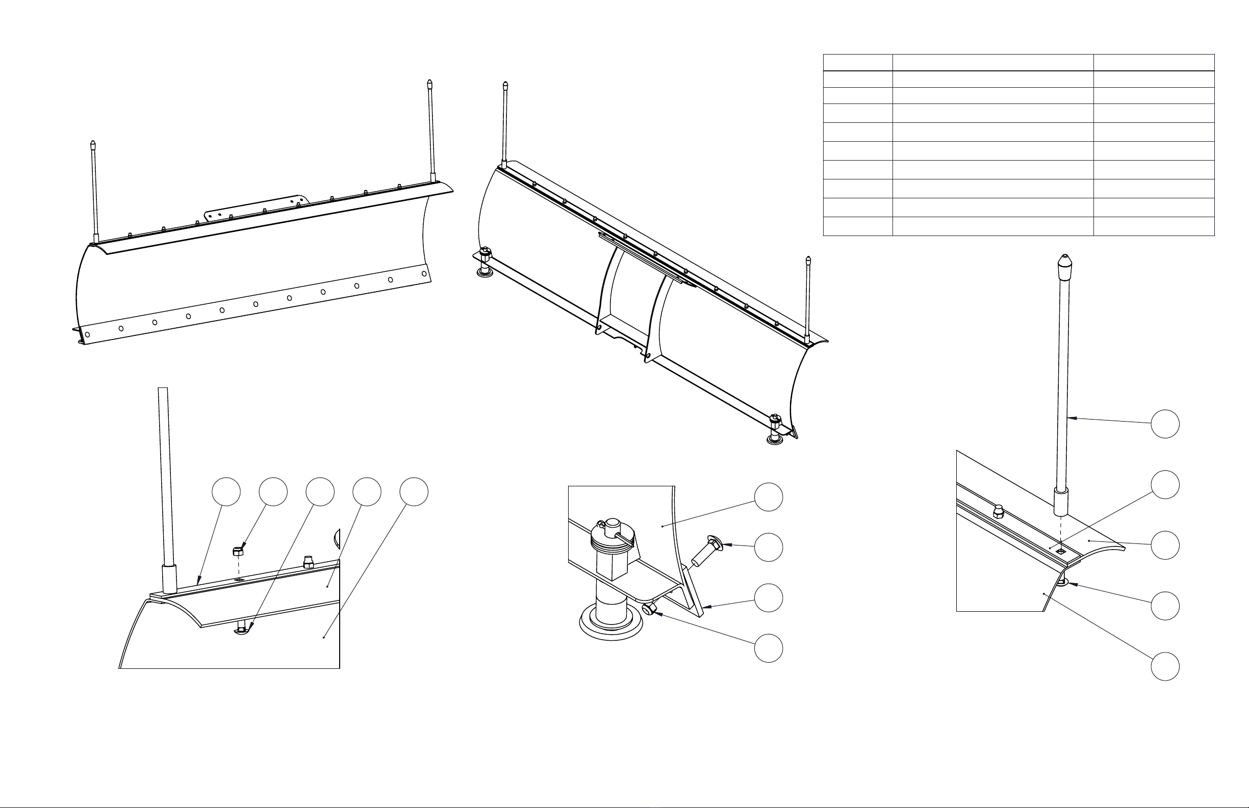
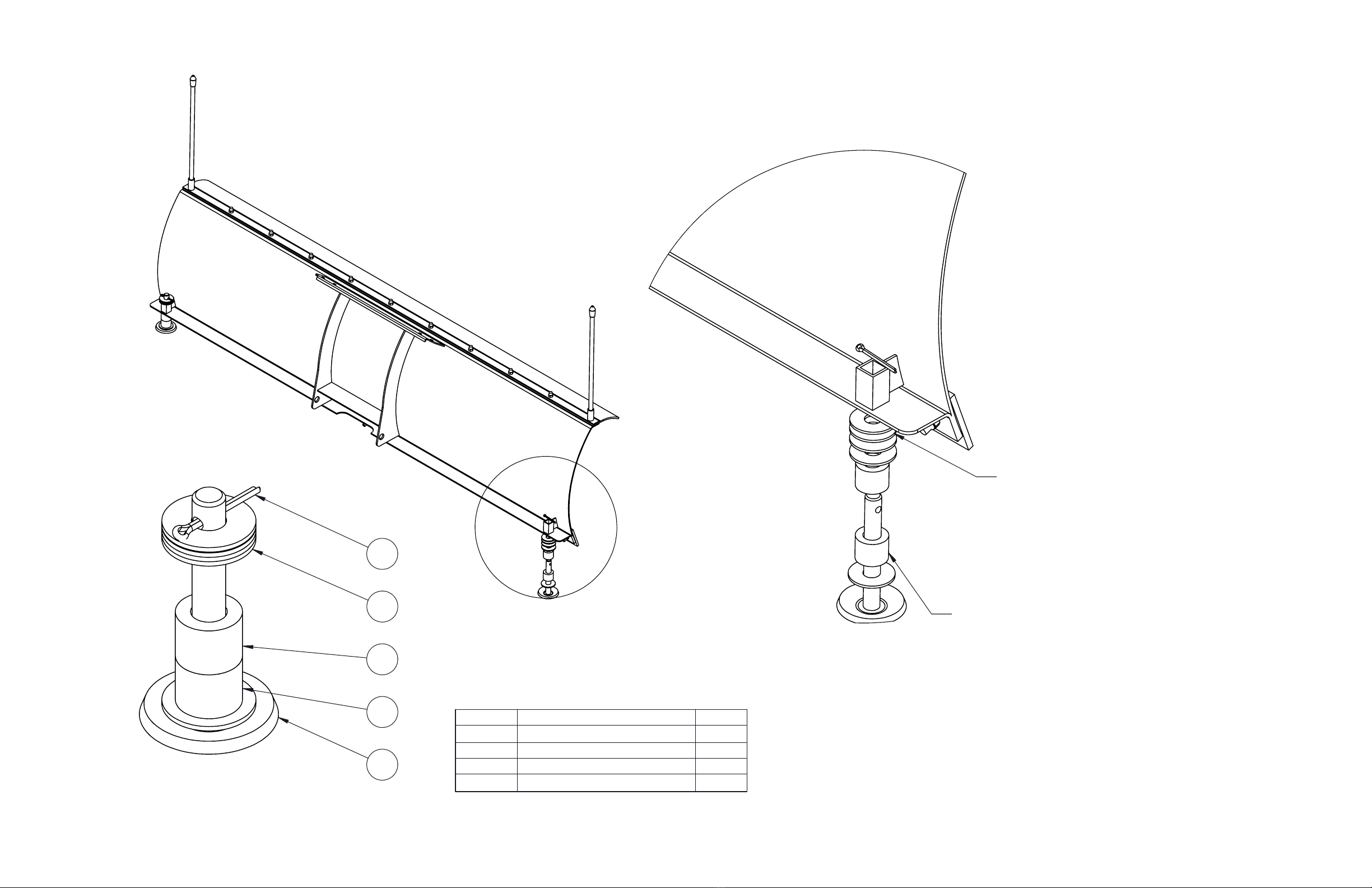
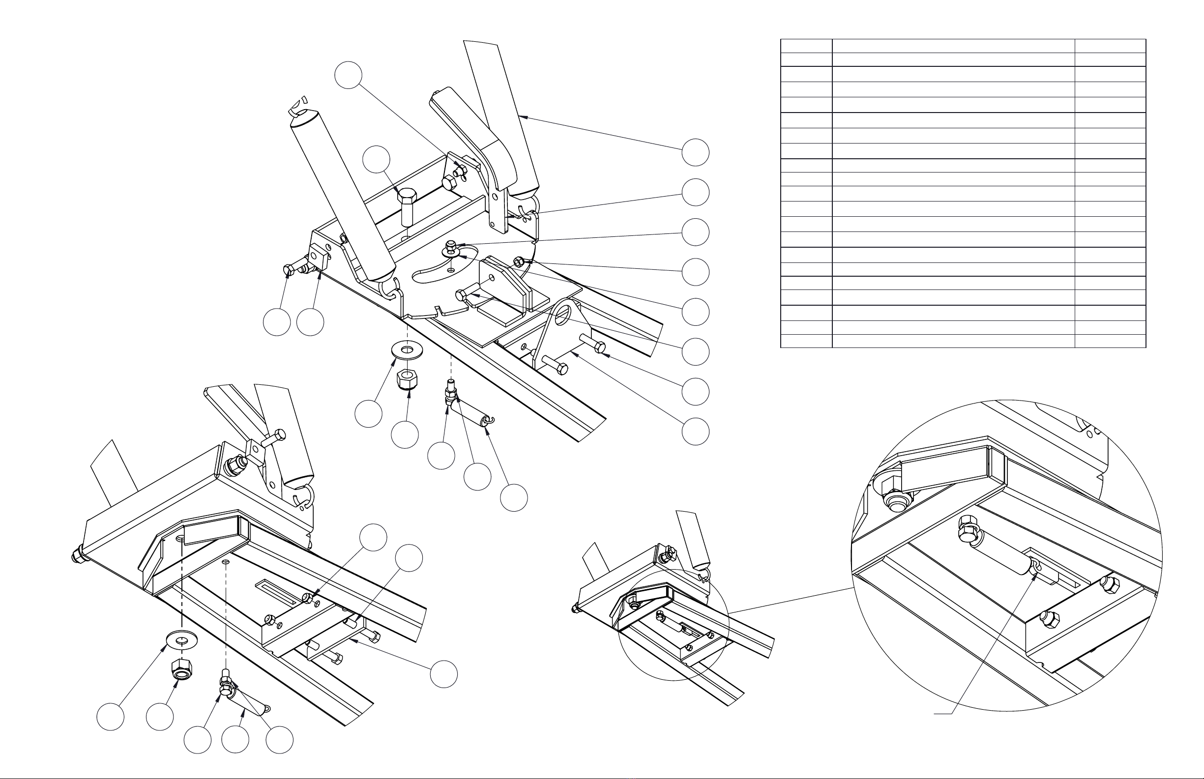
The plow blade assembly is designed to “trip” when it strikes an object or digs in too far.
When pressure is released, the plow springs back into position. Spring tension can be
increased by tightening the hexnuts on the top of the eyebolts. For less spring tension,
loosen the locknuts.
x
The plow skids are adjustable. General skid setting is even with the plow wear bar
bottom edge, higher settings reduce the chance of rocks and gravel from being collected.
x
To increase traction during plow operation, operators can try: Securing weight to the
UTV for additional tire downforce, reducing tire air pressure, or installing tire chains.
SAFETY INFORMATION
Our plow systems were designed with your safety in mind. Please read and understand all
Cautions, Notices and Warnings in this manual before you begin. In order to protect you
and your UTV, certain parts of the plow system and/or hardware are designed to fail when
the equipment is over-stressed.
WARNING
To avoid personal injury or damage to your vehicle: Do not install plow system over plastic
guard components, which can compress over time and loosen the installation, resulting in
poor product performance and/or damage to the UTV. Do not allow mounting hardware
or plow blade to interfere with UTV operational items such as brake lines, coolant hoses,
control cables, steering, electrical or any other function.
BEFORE YOU BEGIN:
x
Please read and understand all instructions.
x
Verify all parts and tools are accounted for.
x
To ensure a satisfactory installation, follow all steps correctly and in the sequence
described.
x
All directions referring to right and left are when the rider is sitting on the machine.
INSTALLATION NOTES: TOOLS REQUIRED:
x
Basic Hand Wrench and Socket Set
x
Plastic Cutting Tool - for opening packaging.
Customer Service
Call: 866-527-7637
Email: [email protected]
1 OF 9
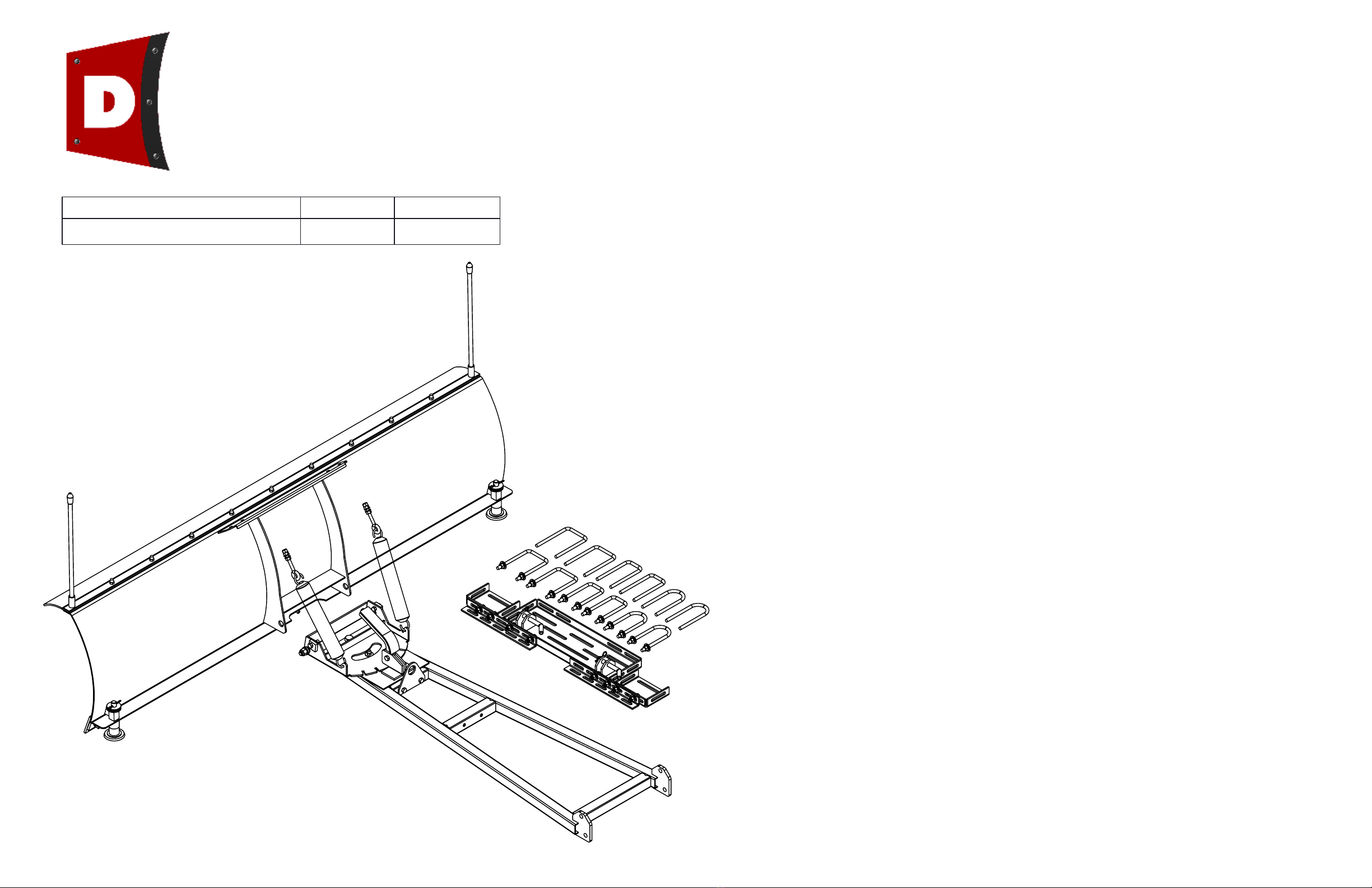
Denali Plows - by Motoalliance
Description
Item #
UPC
72" Denali Universal Plow System
UP72STBK
810541027509

7
3
9
2
Step 2 - Installation of Wear Bar
Repeat 11 locations for this step
Step 3 - Installation of Plow Markers
Secure Plow Marker By screwing onto
Carriage Bolt with Pliers or Vise Grips.
Repeat at 2 locations for this step
1
5
4
8
2
72" Denali Universal Plow System
Step 1 - Installation of Snow Flap Hardware
Repeat 9 locations for this step
7 84 5 2
2 OF 9
Step 1 - Account for Below Listed Items
ITEM NO.
DESCRIPTION
50" Width/QTY.
1
Plow Marker
2
2
Snow Blade
1
3
Cutting Edge - reversable
1
4
Snow Flap Cover Plate
1
5
Rubber Snow Flap
1
6
Snow Blade Skid Plate Assembly
2
7
3/8-16 Nylock Nut
20
8
Carriage Bolt 3/8-16 x 1.00"
11
9
Carriage Bolt 3/8-16 x 1.25"
11

12
10
10
11
13
To increase amount of remaining
snow left on plowed surface, more
more of the washers to the bottom
side of the Black Rubber Spacers.
Various configurations of the shown
components to the left will result in more or less
snow left on the plowed surface. It is best
practice to leave a 1/4" to 1/2" of snow on
plowed surface to prevent excessive wear on
snow plow wear bar.
Step 4 - Installation of Skid Pad
Repeat at both locations for this step
3 OF 9
72" Denali Universal Plow System
ITEM NO.
DESCRIPTION
QTY.
10
Skid Spacer - Black Rubber
2
11
Skid Pad
1
12
5/8" Flat Washer
5
13
.1875 Dia. Cotter Pin
1

4 OF 9
See Page 5 of 9 for complete
listing of all Push Tube Hardware
See Page 8 of 9 for complete
listing of all Frame Mounting Hardware
72" Denali Universal Plow System

Blade Angle Bracket (1x)
Blade Angle Handle (1x)
Trip Spring (2X)
Winch Hook Bracket (1x)
Blade Bushing (2x)
Blade Trip Stop Block (2x)
Latch Spring (1x)
Push Tube Frame (1x)
3/8" Eye Bolt (2x)
5 OF 9
Step 5 - Verify all Push Tube parts are accounted for.
72" Denali Universal Plow System

1922
27
29
17
22
24
26
22
23
18
26
30
21 16
14
26
Do not Install #6, #9
At This Point
Do not Install #13
At This Point
29 27
26
23
14
22 24
17
Hook End of Spring
into hole on end of the
Blade Angle Handle #5
6 OF 9
Step 7 - Assembly of push tube components
72" Denali Universal Plow System
ITEM NO.
DESCRIPTION
Default/QTY.
14
Winch Hook Bracket
1
15
Push Tube with Blade Angle Bracket Assembly
1
16
11.875" x 1.75 x .22 Blade Trip Spring
2
17
3.50" x .70" x .125" Latch Spring
1
18
Blade Angle Handle
1
19
Blade Trip Stop Block
2
20
Blade Bushing
2
21
5/8-11 Hex Bolt 1.75"
1
22
3/8-16 Hex Bolt 1.25"
4
23
3/8-16 Hex Bolt 2.25"
2
24
3/8" Hex Nut
7
25
3/8-16 x 3.00" Eye Bolt
2
26
3/8-16 Nylock Nut
6
27
5/8-11 Nylock Nut
1
28
3/8" Flat Washer
4
29
5/8" Flat Washer
1
30
3/8" Flat Washer
1
31
1/2-13 Nylock Nut
2
32
1/2" x 1.50" Hex Bolt
2
33
1/2" Flat Washer
2

H
18
Plow Blade Assembly
Dia. 3
Dia. 2
Dia. 4
19 20 7
Tighten these two Hex Nuts
against each other once proper
tension on blade trip pressure is determined.
3/8" Hex Nut (3x)
3/8" Flat Washer (2x)
3/8" Eye Bolt (1x)
Trip Spring (1x)
Dia. 1
Blade not shown for clarity
J
Blade Trip Stop Block
3/8" x 1.25" Hex Bolt
Secure with 3/8" Nylock Nut on Inside
AG
Note Direction
of Blade Bushing
7 OF 9
Step 6 - Assembly of Blade to Push Tube Frame.
Assemble Eye Bolts and eye bolt hardware onto plow blade (See Dia. 1)
1.
Assemble Plow Blade to Push Tube Swivel Bracket with provided hardware shown in (Dia. 2)
2.
Secure trip spring into either of the two hole locations on Push Tube swivel bracket (See Dia. 3)
3.
Tip Blade back towards push tube to secure top ends of Trip Springs into eye bolt.
4.
Once both ends of trip springs are secured, install Trip Blade Stop Block (See Dia. 4)
5.
Apply pressure to back of blade pushing forward to
1.
extend the trip springs.
Insert Blade Trip Stop Block along with 3/8" x 1.25" Hex Bolt
2.
thru hole in swivel bracket at this time.
Secure with provided 3/8" Nylock Nut.
3.
Secure trip spring into either of the two hole
locations on Push Tube swivel bracket
72" Denali Universal Plow System

K
45 42 43
35
36
34
44
41
36
DETAIL K
SCALE 1 : 2
38
39
40
37
Note: Final location and hole locations required to mount this
hardware will be determined by the individual UTV application, it may be required
to use a different hole spacing and location depending on your particular installation application.
Please Note!
The Universal Push Tube Design was design to fit
most
Make, Model and Model
years of UTV's.
However, we cannot guarantee this will fit every model or brand on the market.
General UTV vehicle mounting instructions:
Prior to assembling any of the vehicle mounting hardware components
follow the below listed instructions.
Locate a solid frame mounting location that is appropriate for securing the Snow Plow
Vehicle Mounting Components that is located close to the main frame of the vehicle,
preferably on the frame running from the front to back of the machine. Do not secure to
any suspension, brake or mechanical components when selecting your mounting
location for this hardware.
Installation may require removing or drilling of skid plates or protective frame plates,
use caution if drilling into these components to prevent damage to exisiting electrical or
mechanical components.
Be aware of all electrical wiring harnesses, brake lines or any vehicle components that
could come in contact with any of the Snow Plow mounting hardware or plow blade
components so that you do not restrict or prevent the safe operation of your vehicle.
Always inspect for anything that could cause damage to any vehicle components.
The mounting hardware that has been provided for assembly has been provide to be
used in various configurations. Some hardware may not be required depending on your
particular application.
The large “Square” and “U” shaped u-bolts are included to provide various options that
provide greater flexibility for mounting on a wide range of brands and models of UTV’s.
Use the best suited hardware combination that works best with your mounting
application. The hardware and various components has been designed to fit various
widths of frames and mounting locations, this hardware can be configured in various
positions to allow the best flexibility in mounting conditions.
8 OF 9
* The shown examples are for reference only!
* Many other configurations can be used to fit your specific Make, Model or Model Year of UTV.
* Round and/or Square U-Bolts can be used in any combination as required by your specific installtion application.
72" Denali Universal Plow System
ITEM NO.
DESCRIPTION
QTY.
34
Mounting Plate V3
1
35
Extension Plate V3
2
36
Extension Mounting Bracket V3
2
37
Serated Hex Flange Bolt 3/8"-16 x 1 1/4"
8
38
3/8" Flat Washer
20
39
3/8" Lock Washer
20
40
3/8" Hex Nut
20
41
R-Clip Medium
2
42
3/8-16 x 2.00" x 5.50" Long Sqr. U-Bolt
4
43
3/8-16 x 2.00" x 5.50" Long U-Bolt
4
44
1/2" Dia. Bent Hitch Pin
2
45
3/8-16 x 3.00" x 5.50" Long Sqr. U-Bolt
4

U-Bolts and Assembly Hardware
not
shown in these examples.
Note: Final location and hole locations required to mount this
hardware will be determined by the individual UTV application, it may be
required to use a different hole spacing and location depending on your
particular installation application.
9 OF 9
* The shown examples are for reference only!
* Many other configurations can be used to fit your specific Make, Model or Model Year of UTV.
* Round and/or Square U-Bolts can be used in any combination as required by your specific installtion application.
72" Denali Universal Plow System
This manual suits for next models
1
Other Denali Automobile Accessories manuals
Popular Automobile Accessories manuals by other brands

Metra Electronics
Metra Electronics 70-7003 Installation instructions manual

HaWeKo
HaWeKo CVK050 installation manual

Mercedes-Benz
Mercedes-Benz B67876131 installation instructions

Hirschmann
Hirschmann AUTA 3400 F 910 installation instructions

Reimo
Reimo 2806012 Operation manual

iOttie
iOttie Auto Sense 2 Fold user manual