Denali DR1 User manual

Instruction Rev00
0mm 10 20 30 40 50 60 70 80 90
Thank you for choosing DENALI
We know you would rather be riding your bike than wrenching on it, so we go the extra
mile to make sure our instructions are clear and as easy to understand as possible. If
you have any questions, comments, or suggestions don’t hesitate to give our gear
experts a call at 401.360.2550 or visit WWW.DENALIELECTRONICS.COM
Please Read Before Installing
DENALI products should always be installed by a qualified motorcycle technician. If
you are unsure of your ability to properly install a product, please have the product
installed by your local motorcycle dealer. DENALI takes no responsibility for damages
caused by improper installation. Caution: When installing electronics it is extremely
important to pay close attention to how wires are routed, especially when mounting
products to the front fender, front forks, or fairing of your motorcycle. Always be sure
to turn the handlebars fully left, fully right, and fully compress the suspension to
ensure the wires will not bind and have enough slack for your motorcycle to operate
properly.
Installation Tips
We strongly recommend using medium strength liquid thread locker on all screws,
nuts, and bolts. It is also important to ensure that all hardware is tightened to the
proper torque specifications as listed in your owner’s manual. For included accessory
hardware please refer to the default torque specifications provided below. Inspect all
hardware after the first 30 miles to ensure proper torque specifications are
maintained.
Hardware Sizing Guide
Not sure what size bolt you have? Use this ruler to measure screws, bolts, spacers, etc.
Remember, the length of a screw or bolt is measured from the start of the “mounting
surface” to the end of the screw, so only include the screw head when measuring
countersunk screws.
M3 10.0 in-lbs - 1.0 Nm
M4 23.0 in-lbs - 2.5 Nm
M5 44.5 in-lbs 3.5 ft-lbs 5.0 Nm
M6 78.0 in-lbs 6.5 ft-lbs 9.0 Nm
M8 - 13.5 ft-lbs 18.0 Nm
M10 - 30.0 ft-lbs 41.0 Nm
M12 - 52.0 ft-lbs 71.0 Nm
in-lbs
ft-lbs NmBolt Size
0in 1 2 3
What’s In The Box?
DENALIELECTRONICS.COM
DR1 LED Light Kit
DNL.DR1.10000
Instruction Manual
(a) LED Light Pod......................................................................Qty 2
(b) M8 Mounting Hardware.........................................................Qty 2
(c) Spot Lens (installed)............................................................Qty 2
(d) E-Mark Certified True-Hybrid™ Lens.......................................Qty 2
(e) HotSwap™ Single-Intensity Wiring Harness.............................Qty 1
(f) DrySeal™ On-Off Switch.......................................................Qty 1
(g) 7/8” Handlebar Switch Mount................................................Qty 1
Kit Contents
(h) 1” Handlebar Switch Mount...................................................Qty 1
(i) Self Tapping Screw...............................................................Qty 2
(j) Adhesive Pad.......................................................................Qty 1
(k) Zip Tie...............................................................................Qty 4
(l) Instruction Manual................................................................Qty 1
Tools Required: 13mm Wrench, 5mm Allen Key, 4mm Allen Key,
Phillips Head Screw Driver, Test Light, Heat Gun
(h)
(g)
(f)
(e)
(i)
(j)
(d)
(k)
(l)
(b)
(c)
(a)

1. Mounting The Lights
2. TriOptic™ Multi-Beam Lens System
1.1 - Choosing The Mounting Location
DENALI offers dozens of universal and vehicle specific light mounts. To
determine the best mounting location consider the following tips. For
maximum beam distance at night, mount the lights higher up. For
maximum day time visibility, mount the lights down low to increase your
overall lighting footprint. To create the optimum lighting and visibility
package, mount one pair of long distance spots up high for night time
distance and one pair of flood or hybrid lights down low for day time
visibility and night time fill.
Check out our full mounting application chart at DENALIELECTRONICS.COM
to see all the mounting options available for your vehicle.
DENALIELECTRONICS.COM
1.2 - Mounting The Light
Step One: Use a 13mm wrench and the included M8 screw, washer, nut
and nut cap to attached the pods to the mounting bracket.
Step Two: Use the M8 plastic nut cap to cover the nut and exposed
thread.
Note: The light pods can be mounted in both horizontal and vertical
orientations. See Figure 2.2 for instructions on how to rotate the lens in
the housing of the pod.
2.1 - Beam Options
This LED light kit includes two spot lenses and two True-Hybrid™ lenses.
Use two spots for maximum distance, two Hybrid lenses for a 50/50
True-Hybrid™ or one of each to create a Spot-Hybrid that adds some
additional close range fill while maintaining distance.
All DENALI lenses are also available in amber. The amber color of the
lens increases visibility in fog and rain by blocking blue frequencies from
the light, which reflect off water vapor and decrease vision.
2.2 - Installing The Lenses
Step One: Remove the four M4 screws from the rear of the light pod, then
remove the bezel and lens from the light pod.
Step Two: Remove the rubber gasket from the original lens and re-install
it onto the new lens.
Step Three: Re-assemble the light pod making sure the gasket is properly
seated and creating a seal, then secure the bezel using the M4 screws.
Keep in mind the light pods can be mounted in both horizontal and vertical
orientations. Just be sure to rotate diffused lenses 90 degrees so the flutes
remain in the vertical orientation.
Spot
True-Hybrid™ (E-Mark Certified)
Spot Hybrid
Crashbar/Engine Guard/
Frame Mount
Fork Tube Mount
Fender Mount
DR1 Pod
M8x20 Bolt
Example Bracket
M8 Washer
M8 Nut
M8 Nut Cap
DR1 Pod
Gasket Lens
Bezel
Screws
Horizontal Mounting Vertical Mounting
Vehicle Specific Fairing Mount
Vertical Flutes
Vertical Flutes

3. Wiring The Lights
3.1 - Wiring Harness Overview
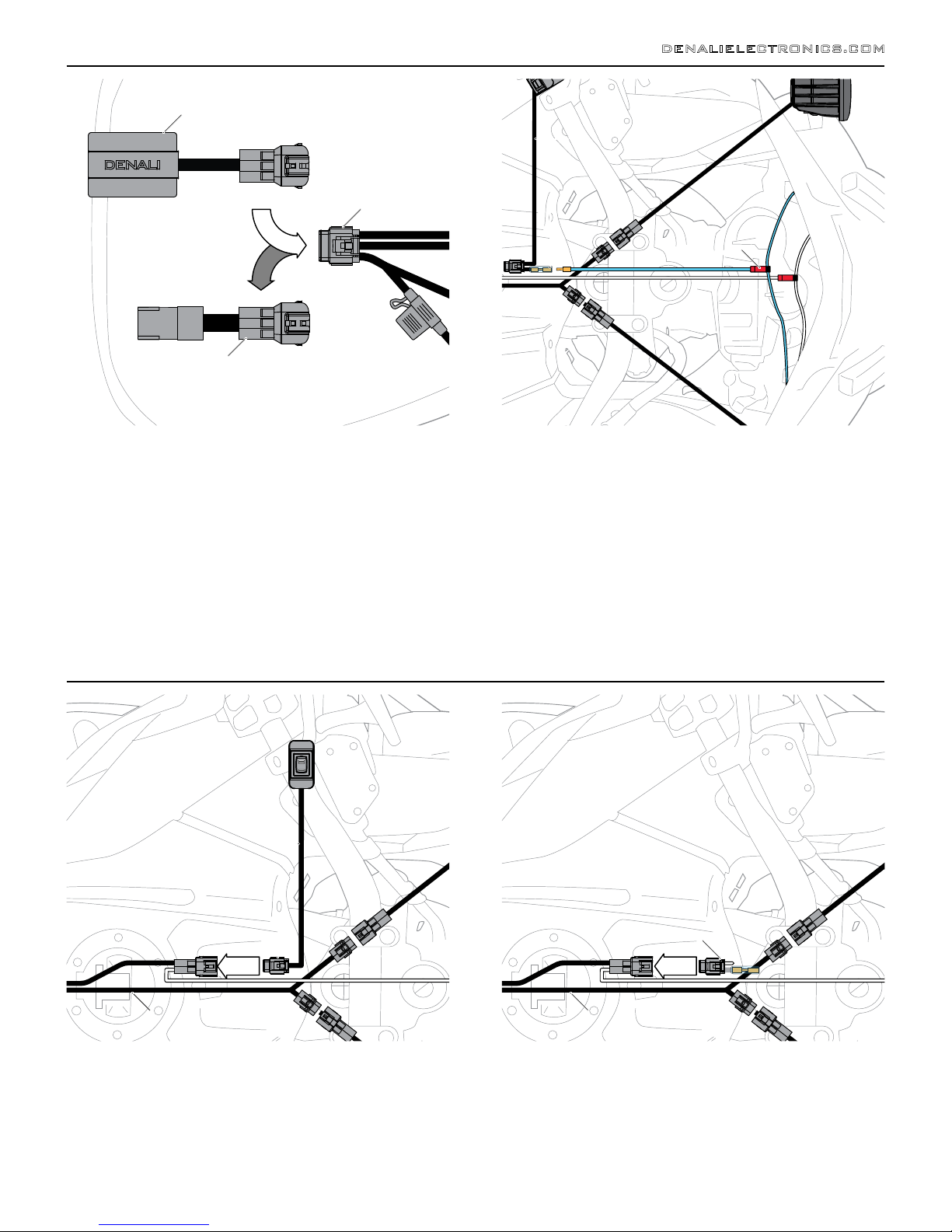
Our premium wiring harness features high-quality waterproof components
and a clever HotSwap™ design that enables an effortless swap from the
standard Single-Intensity relay to our Dual-Intensity DataDim™ Controller
(Sold Separately). If adding the DataDim™ Controller upgrade now, jump
ahead and read Section 6 before returning to Section 3.2. If not, continue
to Section 3.2 with peace of mind that you can always upgrade later,
without having to rewire the lights.
Note: The DENALI harness with pods connected is 60 inches in length.
DENALI Harness Extensions are available for purchase if extra length is
required.
DENALIELECTRONICS.COM
Step One: Find a suitable location near the battery to store the
Single-Intensity Relay.
Step Two: Begin routing the harness towards the mounted light pods.
Secure the harness to the vehicle’s frame along the way with the
included zip ties. Be sure to avoid any moving components such as fan
blades or suspension. Plug the light pods into the base harness.
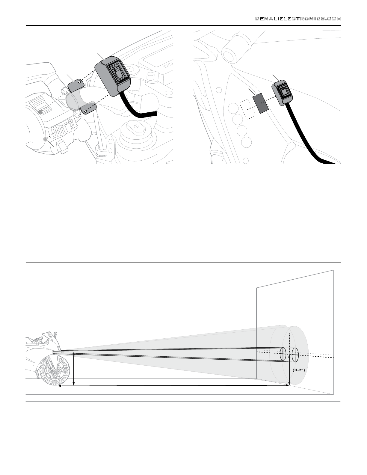
Step Three: Route the switch wire to the location where the switch will
be mounted and secure it to the vehicle using zip ties. See Section 4 for
switch mounting options.
3.3 - Tapping Switched Power
Step One: Two examples of possible switched power sources are the
low beam and tail light, however there are many other possible sources
in most vehicles. The simplest way to identify switched power is to use a
test light to probe connectors/wires while cycling the ignition. A clean
switched power source will only be live when the ignition is cycled “ON”,
it should lose power when the ignition is cycled “OFF”.
Step Two: Once a proper switched power source has been identified
use the included Posi-Tap to tap the white trigger wire into the identified
switched power source.
3.4 - Connecting To The Battery
Step One: Remove the fuse from the fuse holder.
Step Two: Access the vehicle’s battery and disconnect the negative (-)
and positive (+) terminals.
Step Three: Connect the DENALI wiring harness to the battery via the
ring terminals, be sure the red wire lead with the fuse holder in-line
goes to the positive (+) terminal of the battery.
Step Four: Re-install the fuse into the fuse holder.
Note: When possible, place the fuse holder in an easily accessible
location for convenient service in the event of a blown fuse.
+
-
3.2 - Routing The Wiring Harness
Single-Intensity Relay
Base Harness
On-Off Switch
Fuse Holder
Battery
+
-
Battery
Posi-Tap
DR1 Pod
Trigger Wire

4. Mounting The Switch
4.1 - Handlebar Mounting
All DENALI Light Kits include both 7/8” and 1” handlebar mounting
bands, as well as an adhesive mounting pad.
Step One: Determine the bar diameter and select the correct size
mounting band, then place the band around the handlebar.
Step Two: Use the two self tapping screws and a #1 Phillips head screw
driver to attach the switch to the mounting band. Continue tightening
the screws until the switch no longer rotates on the handlebar.
DENALIELECTRONICS.COM
4.2 - Surface Mounting
Step One: Clean and prep the mounting surface and the bottom of the
switch using an alcohol swab. Allow surfaces to fully dry.
Step Two: Peel away one side of the backing from the adhesive pad
and adhere the pad to the bottom side of the switch.
Note: To ensure a stronger bond use a heat gun to warm the tape
before applying to the surface.
Step Three: Peel away the remaining backing from the adhesive pad
and adhere the switch to the mounting surface using moderate
pressure.
5. Aiming The Lights
5.1 - Suggested Aiming Method
Step One: With someone sitting on the bike and holding it upright on
level ground, position the vehicle 25 feet from a flat and vertical wall.
Be sure the wall is large enough that both beams can be projected onto
the wall. A garage door is a great place to perform this procedure.
Step Two: Measure the distance from the ground to the center of the
light pods (H)
Step Three: Using tape, make a horizontal line that is 2 inches lower
than the previous measurement from the ground to the center of the
lights (H-2”).
Step Four: Loosen the mounting and hinge bolts then aim each light so
that the center of the hot spot aligns with the tape line on the wall. The
lights should be aimed equidistant left and right from center line of the
vehicle.
Step Five: Once final adjustments are made to the lights, tighten the
mounting and hinge bolts.
Congratulations! The DENALI LED Light Kit has been successfully
installed! Enjoy! Refer to Figures 6 & 7 for detailed instructions for
installing optional DENALI Light Kit accessories. To view a full list of
accessories please visit WWW.DENALIELECTRONICS.COM
(25 FEET FROM WALL)
(H-2”)
(H)
(H)
Switch
Mounting Band Switch
Adhesive Pad
Self Tapping Screws
If you have limited space or are having trouble identifying the hot spot on the wall, you can shorten the distance to 6 feet and mark the tape line at H-1/2".

6. DataDim™ Controller Upgrade
6.1 - DataDim™ Controller Overview
DENALI 2.0 Light pods are equipped with a dedicated 3rd-wire dimming
circuit so we can use an external signal to reliably control the intensity
of the LED chip at the source. Plug in our Dual-Intensity DataDim™
Controller to enable the DENALI lights to switch between half and full
intensity with your vehicle’s original high beam switch.
Step One: Unplug the Single-Intensity Relay from the Base Harness.
Step Two: Plug the Dual-Intensity DataDim™ Controller into the Base
Harness.
6.2 - Tapping The High Beam
Step One: Plug the blue Dual-Intensity Trigger wire into the bullet
connector at the base of the On-Off Switch.
Step Two: Use a test light while toggling the vehicles high beam switch
to identify the wire which receives power upon high beam activation.
Step Three: Once the high beam trigger has been identified, use the
included Posi-Tap to tap into the wire.
Note: Some vehicles are equipped with LED headlights or other lighting
systems that do not provide a clean 12v high beam trigger signal. See
Figure 7.1 for an overview of our independent dimming switch.
7. Switching Options
DENALIELECTRONICS.COM
7.1 - Hi-Low-Off Switch Option
The DENALI Hi-Low-Off Switch enables independent dimming of the
lights, separate from the vehicles OEM lighting system. This eradicates
the issues presented by vehicles that do not provide and a clean 12v
high beam trigger signal. This switch is also a great option for those who
want full independent control of their auxiliary lights.
Note: The Dual-Intensity DataDim™ Controller option is required to
install this switch.
Step One: Unplug the standard On-Off switch from the base harness.
Step Two: Plug the Hi-Low-Off Switch into the base harness.
7.2 - Switch Eliminator Option
The DENALI Power Switch Eliminator plug replaces the standard On-Off
switch so your lights will automatically power on and off with the
vehicles ignition. Enjoy the convenience of having your lights on any
time your bike is running and peace of mind knowing they will turn off
with the ignition.
Note: This switch eliminator removes the ability to independently shut
the auxiliary lights Off while the vehicle is running.
Step One: Unplug the standard On-Off switch from the base harness.
Step Two: Plug the Switch Eliminator into the base harness.
DataDim™ Controller
Base Harness
Single-Intensity Relay
On-Low-Off Switch
Switch Eliminator
Base Harness Base Harness
Posi-Tap
Bullet Connector
On-Off Switch
Table of contents
Other Denali Lighting Equipment manuals
Popular Lighting Equipment manuals by other brands

Somogyi Elektronic
Somogyi Elektronic home DL 210L instruction manual

Nemalux
Nemalux AR Series installation manual

Larson Electronics
Larson Electronics EPL-WPLED-100W-RT-PSC instruction manual

Clevertronics
Clevertronics L10 LBS2N Series Installation & Maintenance Instruction Manual

TPL VISION
TPL VISION SDOME II 130 user guide

Viessmann
Viessmann 6005 Operation manual