manuals.online logo
Brands
  1. Home
  2. •
  3. Brands
  4. •
  5. Denon
  6. •
  7. Amplifier
  8. •
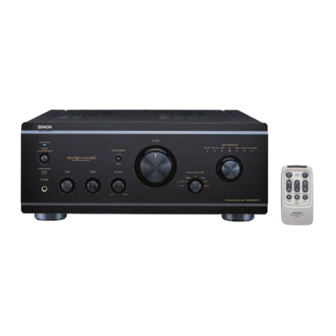
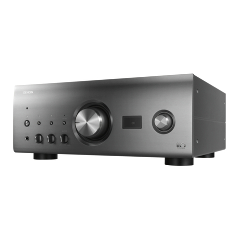
  9. Denon PMA-925R User manual

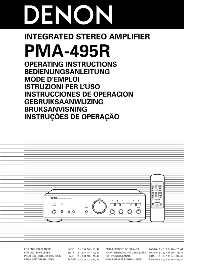
Denon PMA-925R User manual

[)
a
N
©
N
Hi-Fi
Integrated
Stereo
Amplifier
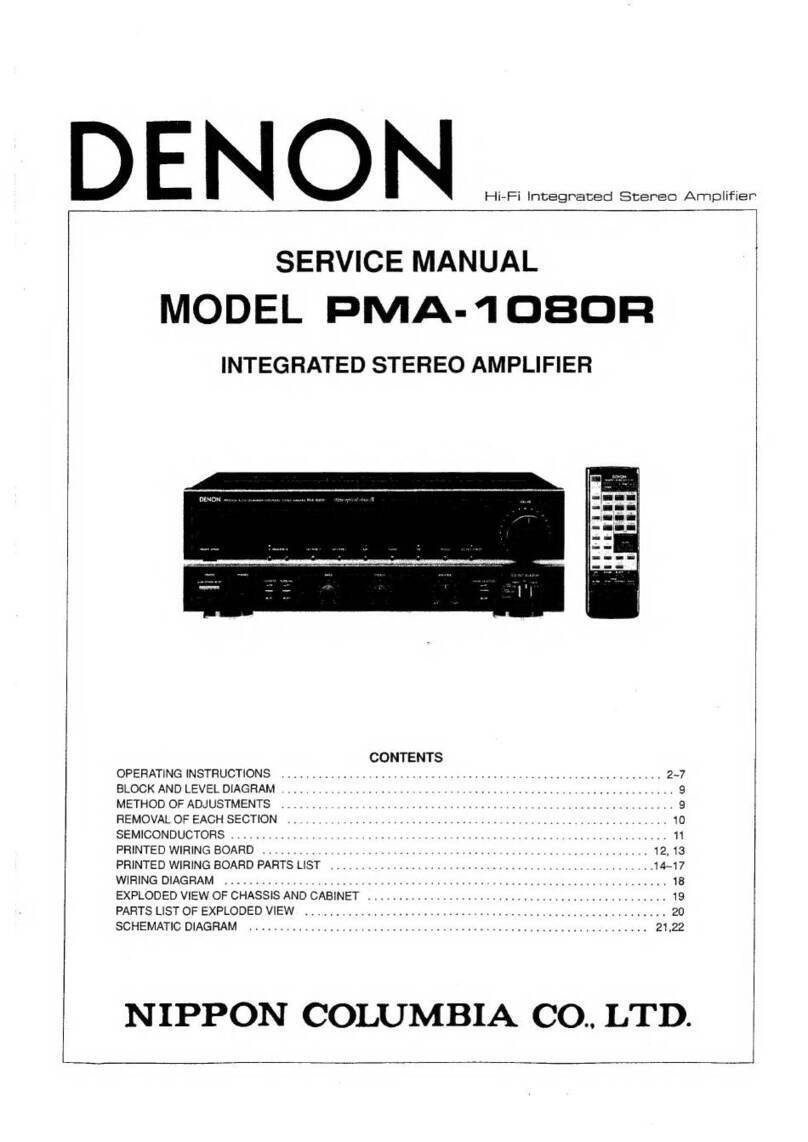
SERVICE
MANUAL
MODEL
PMA-925R/725R
INTEGRATED
STEREO
AMPLIFIER
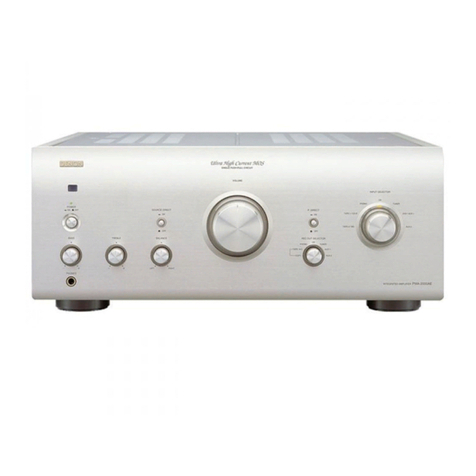
PMA-925R
DENON
wrconrctnenies
aren
uerrmeamens
amit
tc
7
0
606
©
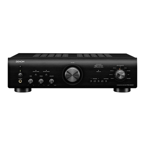
PMA-725R
CONTENTS
OPERATING
INSTRUCTIONS
......0
0.
ccc
cece
ccc
e
tence
een
eee
e
een
n
enn
e
ence
ete
e
eee
eeennnee
2-7
REMOVAL
OF
EACH
SECTION
......-0.
cee
cece
cece
terete
nen
e
teen
een
n
een
e
nen
nets
8,9
FUNCTION
OF
NEW
CIRCUIT........0
00
ccc
ccc
cence
nee
ence
ence
nee
e
rene
en
ence
nen
etree
eens
10,11
METHOD
OF
ADJUSTMENTS
......
00
cece
ec
cee
cece
renee
een
e
een
erent
ene
e
tenet
nee
erent
12
BLOCK
AND
LEVEL
DIAGRAM
.......-
fe
ein
th
ek
acta
anata
tye
aoead
aailiverahinata
Axe
daRae
atte
aS
iis
8
esraele
a
aabax
MiSs
13
SEMICONDUCTORS
<ceeiccaccvs
suis
smandcwsinauune
soma
eau MEe
ewe
bat
epiane
sels
eurie
awa
a
hue
eating
sun
e's
14,15
PRINTED
WIRING
BOARD
........0.
0c
cece
cece
cence
een
ne
renee
b
nen
nee
e
eee
n
tenn
ene enn
eenes
16~19
NOTE
FOR
PARTS
LIST
2c...
cco
sé
cateesvere
sc
pack
gc
ae
ey
ieco
cases
du
aapsad
lel
eieun
Penne
POGWY
ES
RUA
EL
TR
EAM
OFS
20
PARTS
LIST
OF
P.W.B.ASS'Y
....cccc
ces
ec
sews
ce
cbse
scape
ne
rene
ree
wea
ensaeenenseeen
ence
ntee
dy
20-25
PNALO2
SER
oe.
sceccc
vee
x
chiar:
Grbsttin
+
a
ueaectitegiile
Sig's
o
Pea
ESA
ARE
RSE
ERR
TNT
Contes
sihested
adecaaeetete
aac
a
20~23
PUMASZOSR
om
ios
cic
sc
tewco
cece
p
gine
5
wid
ls
oe
Mela
Casa
dad
ans
wR
PME
EES
S
COLTS
WEE
Saye
eee)
Meade
sett
23~25
EXPLODED
VIEW
OF
CHASSIS
AND
CABINET,
PARTS
LIST
OF
EXPLODED
VIEW
..........-002
005s
es
26~29
PRAA
GDB
oc
otc
cck
case’
soc
sus
sed
Sia
BE
RGN
eS
wes
ee
waa
aroha
lee
BAG
UES
FAW
eae
Suscncal
os
Ad
si
inder
Sc
deudl
ao
eT
NS
26,27
PRAASFOSER
ces
cuss
es
sittin
bane
e
coedss
bo
sets'sloibiuniva
a
Gita
vied
8A
3
Wate
SME
a
SY
eres
a
ae
a
ace
6
aeeyh
coed
&
ls
gone
aad
28,29
WIRING
DIAGRAM
..............--65
ot
sates
te
diy
wi
ddnon
Baki
Ronee
kth
s
USexe
reas
ys
SER
TNST
aie
aE
eo
we.
30
SCHEMATIC
DIAGRAM
.......0.
0c
e
cece
cece
cece
nec
cece
eee eee
eet
e
eee
beeen
eee
n
ence
een
nese
teens
31-34
PIMASQDBR
sche
cccdice
cco
tes
2
baited
mcidneys
Oosnigs
a
Genesee
parsed
Ad
ig
ie
ee
ROSS
RG
Boe
PEM
ee
pp
31,32
PRA
ASIDES
PR
cess
so
cbt.
nd
sce
4
gu
eden
unea
hte
be
eaten
Meh
ene
tea
e
uae
Pine
gidegtd
hadsann.
tne
sons
ANNA
SOS
Be
SD
33,34
NIPPON
COLUMBIA
CO.
LTD.
CAUTION
RISK
OF
ELECTRIC
SHOCK
DO
NOT
OPEN
CAUTION:
TO
REDUCE
THE
RISK
OF
ELECTRIC
SHOCK,
DO
NOT
REMOVE
COVER
(OR
BACK).
NO
USER
SERVICEABLE
PARTS
INSIDE.
REFER
SERVIC-
ING
TO
QUALIFIED
SERVICE
PERSONNEL.
The
lightning
flash
with
arrowhead
symbol,
within
an
equilateral
triangle,
is
in-
tended
to
alert
the
user
to
the
presence
of
uninsulated
“dangerous
voltage”
within
the
product's
enclosure
that
may
be
of
sufficient
magnitude
to
constitute
a
risk
of
electric
shock
to
persons.
The
exclamation
point
within
an
equilateral
triangle
is
intended
to
alert
the
user
ta
the
presence
of
important
operating
and
maintenance
(servicing)
instructions
in
the
literature
accompanying
the
appliance.
WARNING:
TO
REDUCE
THE
RISK
OF
FIRE
OR
ELECTRIC
SHOCK,
DO
NOT
EXPOSE
THIS
APPLIANCE
TO
RAIN
OR
MOISTURE.
@
FOR
U.S.A.
&
CANADA
MODEL
ONLY
CAUTION
TO
PREVENT
ELECTAIC
SHOCK
DO
NOT
USE
THIS
(PO-
LARIZED}
PLUG
WITH
AN
EXTENSION
CORD,
RECEPTACLE
OR
OTHER
OUTLET
UNLESS
THE
BLADES
CAN
BE
FULLY
IN-
SERTED
TO
PREVENT
BLADE
EXPOSURE
@
POUR
LE
MODELE
CANADIEN
UNIQUEMENT
ATTENTION
POUR
PREVENIR
LES
CHOCS
ELECTRIQUES
NE
PAS
UTILIS-
ER
CETTE
FICHE
POLARISEE
AVEC
UN
PROLONGATEUR
UNE
PRISE
DE
COURANT
OU
UNE
AUTRE
SOATIE
DE
COU-
RANT,
SAUF
SI
LES
LAMES
PEUVENT
ETRE
INSEREES
A
FOND
SANS
EN
LAISSER
AUCUNE
PARTIE
A
DECOUVERT.
DECLARATION
OF
CONFORMITY
We
declare
under
our
sole
responsibilty
that
the
product
premain
Amputier
PMA-925R/
725A
10
which
this
declaravon
relates
is
in
contormity
with
the
follow:
ing
standards
£N5S013,
EN55020,
ENG0555-2
and
EM60555-3
UBEREINSTIMMUNGSERKLARUNG
Wir
erklaren
unter
unserer
Verantwortung,
dag
das
Produkt
Vor-Hauptverstarler
PMA-925R/
725R,
aul
das
sich
diese
Erklarung
bezeht,
den
folganden
S:ac
daras
eatspricnt
ENS$013,
EN55020,
ENG0555-2
und
EN60555-3
DECLARATION
DE
CONFORMITE
Nous
declarons
sur
notre
seule
responsabiliie
que
l'appareil
Ampéf.catear
PhIA-925R/725R
auquel
se
raféra
cette
déclaration
est
conforme
aux
slanaascs
suivants:
EN55013,
€N55020,
ENG0555--2
et
ENG0555-3.
DICHIARAZIONE
DI
CONFORMITA
Dichiariamo
con
piana
responsahilita
che
it
prodotto
ampiiicatore
di
precedenza
PMA-925R/725R,
al
quale
questa
dichiarazione
si
rifensce,
@
conforme
ale
seguenti
normative:
€NS55013,
EN58020,
EN60555-~2
e
ENG0555-3,
DECLARACION
DE
CONFORMIDAD
Declaramos
bajo
nuestra
unica
responsabilidad
que
e!
producto
precedente,
el
Amplificador
PMA-925R/725R,
al
que
esta
declaracion
hace
referencia,
es
conforma
con
los
siguientes
estandares:
EN55013,
EN55020,
EN60555-2
y
EN60555-3
EENVORMIGHEIDS
VERKLARING
Wit
verklaren
urlsluitend
op
onze
verantwoordelikheid
dat
het
produkt
waarop
deze
verklaring
betrekking
heeft,
de
voorversterker
PMA-925R/
7258,
in
over-
Benstamming
is
met
de
volgende
normen
ENS55013,
EN55020,
EN60555-2
en
EN60555-3.
OVERENSSTAMMELSESINTYG
Harmed
intygas
hell
pd
eget
ansvar
att
produkten,
{érforstarkare
/
slutsteg
PMA~925R
/725R,
vilken
detta
intyg
hanvisar
tit
uppiylier
féljande
standarder
EN65013,
EN55020,
EN60555-2
och
EN60555-3
DECLARAGAO
DE
CONFORMIDADE
Declaramos
sob
nossa
exchisiva
responsabitidade
que
o
produto
pre
Aiiphicador
Principal
PMA-925R/725R
ao
qual
esta
declaragao
corresponde,
esta
en”
contormidade
com
as
sequintes
normas:
END5O1G, EN9S020,
ENGOSIS-2
@
ENGQ555-3
6A.
10
1
FOR
U.S.A.
MODEL
ONLY
SAFETY
INSTRUCTIONS
Read
Instructions
—
All
the
safety
and
operating
instruc-
12,
tions
shouid
be
read
before
the
appliance
is
operated.
Retain
Instructions
-
The
safety
and
operating
instruc-
tions
should
be
retained
for
future
reference.
Heed
Warnings
-
All
warnings
on
the
appliance
and
in
the
operating
instructions
should
be
adhered
to.
14
Follow
Instructions
-
All
operating
and
use
instructions
should
be
followed.
15.
Water
and
Moisture
-
The
appliance
should
not
be
used
near
water
-
for
example,
near
a
bathtub,
washbowi,
16
kitchen
sink,
laundry
tub,
in
a
wet
basement,
or
near
a
swimming
pool,
and
the
like
Carts
and
Stands
-
The
appliance
should
be
used
only
with
a
cast
of
stand
that
is
recommended
by
the
manufacturer.
An
appliance
and
cart
combination
should
be
moved
with
care.
a
Quick
stops,
exces-
i,
|
sive
force,
and
uneven
surfaces
may
cause
A
\
7
the
appliance
and
cart
Ta
=
combination
to
overturn.
—_
Wall
or
Ceiling
Mounting
-
The
appliance
should
be
18,
mounted
to
a
wall
of
ceiling
only
as
recommended
by
the
manufacturer
Ventilation
-
The
appliance
should
be
situated
so
that
its
19.
location
or
position
does
not
interfere
with
its
proper
ven-
tilation.
For
example,
the
appliance
should
not
be
si-
tuated
on
a
bed,
sofa,
rug,
or
similar
surface
that
may
block
the
ventilation
openings;
or,
placed
in
a
built-in
installation,
such
as
a
bookcase
or
cabinet
that
may
im-
pede
the
flow
of
air
through
the
ventilation
openings
Heat
-
The
appliance
should
be
situated
away
from
heat
sources
such
as
radiators,
heat
registers,
stoves,
or
other
apptiances
{including
amplifiers)
that
produce
heat.
Power
Sources
-
The
appliance
should
be
connected
to
&
power
supply
only
of
the
type
described
in
the
operat-
ing
instructions
or
as
marked
on
the
appliance.
Grounding
or
Polarization
—
Precautions
should
be
taken
so
that
the
grounding
or
polarization
means
of
an
ap-
pliance
is
not
defeated
FIQURE
A
EXAMPLE
OF
ANTENNA
GROUNOING
‘AS
PER
NATIONAL
ELECTRICAL
CODE
ANTTNE,
ceaam
wre
ANIENHS,
DISCHARGE
UNI
WHEE
SEC
TRO
619-20:
Recta
SERY
EQUIP
ENT
GAQUNDING
CO*
WHET
SECTION
810-2
HES
~
HATONAL
ELECTRICAL
COOE
20.
Power-Cord
Protection
-
Power-supply
cords
should
be
routed
so
that
they
are
not
likely
to
be
walked
on
or
pinched
by
items
placed
upon
or
against
them,
paying
particular
attention
to
cords
at
plugs,
convenience
recep-
tacles,
and
the
point
where
they
exit
from
the
appliance.
Cleaning
~
The
appliance
should
be
cleaned
only
as
rec-
ommended
by
the
manufacturer.
Power
Lines
~
An
outdoor
antenna
should
be
located
away
from
power
lines.
Outdoor
Antenna
Grounding
~
if
an
outside
antenna
is
connected
to
the
receiver,
be
sure
the
antenna
system
is
grounded
so
as
to
provide
some
protection
against
voltage
surges
and
built-up
static
charges.
Article
810
of
the
National
Electrical
Code,
ANS|/NFPA
70,
provides
in-
formation
with
regard
to
proper
grounding
of
the
mast
and
supporting
structure,
grounding
of
the
lead-in
wire
to
an
antenna-discharge
unit,
size
of
grounding
conduc-
tors,
location
of
antenna-discharge
unit,
connection
to
grounding
electrodes,
and
requirements
for
the
ground-
ing
electrode.
See
Figure
A.
Nonuse
Periods
~
The
power
cord
of
the
appliance
should
be
unplugged
from
the
outlet
when
left
unused
for
a
long
period
of
time.
Object
and
Liquid
Entry
-
Care
should
be
taken
so
that
ob-
jects
do
not
fall
and
liquids
are
not
spilled
into
the
encto-
sure
through
openings
Damage
Requiring
Service
-
The
appliance
shouid
be
serviced
by
qualified
service
personnel
when:
A
The
power-supply
cord
or
the
plug
has
been
dam-
aged;
or
8.,
Objects
have
fallen,
or
liquid
has
been
spilled
into
the
appliance;
or
Cc.
The
appliance
has
been
exposed
to
rain;
or
D.
The
appliance
does
not
appear
to
operate
normally
or
exhibits
a
marked
change
in
performance;
or
€.
The
appliance
has
been
dropped,
or
the
enclosure
damaged.
Servicing
-
The
user
should
not
attempt
to
service
the
ap-
pliance
beyond
that
described
in
the
operating
instruc-
tions.
All
other
servicing
should
be
referred
to
qualified
service
personnel.
ge
PERES
TENS
eT
Raee
el
HSeZ/Hesee-vWc
wee
NOTE:
}.
Always
keap
the
POWER
switch
on
the
main
unit
turned
on.
2.
Turn
the
power
on
and
off
from
the
ramoate
contol
unit
3,
Unplug
the
power
cord
when
you
do
not
plan
to
use
the
unt
for
along
period
of
ume.
CAUTION:
tf
only
the
MUTE/STANDBY
LED
is
lit,
this
means
that
the
power
is
tuned
off
from
the
remote
control
unit.
Turn
the
power
on
from
the
ra-
mote
contro!
unit
HINWEIS:
1.
Lassen
Sie
den
Netzschalter
(POWER)
am
Hauptgerat
stets
eingeschaltet,
2.
Schalten
Sie
den
Strom
mit
dam
Fernbedienungsgerat
ain-und
aus.
3.
Trennen
Sie
das
Netzkabet
vom
Netz
ab,
wenn
Sie
beabsichtigen,
das
Gerat
iiber
einen
langeren
Zaitraum
hinweg
nicht
zu
benutzen.
VORSICHT:
Wenn
nur
das
Stunimschalt-/Bereitschalts-LED
(MUTE/STANDBY)
lauchtet,
$0
bedeutet
dies,
dat
der
Strom
vom
Fernbedienungsgerat
aus
ausgaschaltet
worden
ist.
Schaltan
Sie
den
Strom
vom
Fernbedienungs-
gerat
aus
ain
REMARQUE:
1.
S‘assurer
que
le
commutateur
d’alimentation
(POWER)
sur
l'unite
principale
Sort
toujours
dans
fa
position
activéee.
2.
Allumer
et
ateindre
l'apparerl
avec
{a
télécommande.
3.
Debrancherle
cordon
d'alimentation
lorsque
l'appareil
ne
sera
pas
utilisé
pen-
dant
une
longue
période
ATTENTION:
Si
seul
le
temoin
(LED}
de
sourdine/veile
(MUTE
/STANOBY}
est
allurna,
cela
signitie
que
l'appareil
est
mis
hors
circuit
parla
tétécommande
Alla
myer
l'appareil
avec
la
télecommanda.
NOTA:
1,
Tenere
sempre
l'interruttore
detla
corrente
POWER}
detl’unita
principale
nella
posizione
di
attivazione.
Accendets
e
spegnete
la
corranta
usando
4
telecomando.
2.
3.
Scollegate
il
filo
di
alimentazione
quando
avete
intenzione
di
non
usare
lappa:
fecchio
per
uA
lingo
periodo.
AVVERTENZE:
Se
sono
illuminati
solo
i
LED
di
attenuazione/attesa
(MUTE
/
STANDBY},
quasto
significa
che
la
corrente
e”
stata
spenta
con
tt
telecomando.
Riac-
cendete
la
corrente
usando
1!
telecomando.
PRECAUTIONS
FOR
INSTALLATION
Leave
at
feast
10cm
of
space
between
this
unit
and
any
other
component
placed
above.
SICHERHEITSMASSNAHMEN
BEIM
EINBAU
Lassen
einen
Mindestabstand
von
10
cm
zwischen
diesem
Gerat
und
der
ande-
ran
Komponente,
die
darautgestellt
wird.
PRECAUTIONS
D'INSTALLATION
Prevoir
un
espace
d’au
moins
10cm
entre
l'unité
et
tout
autre
apparel
se
trouvact
au-dessus.
PRECAUZIONI
PER
LINSTALLAZIONE
Lasciate
uno
spazio
libero
di
almeno
10
cm
fra
quest’
umita
e
qualsias:
altro
campe-
nente
che
&
collocato
sopra
la
siessa
NOTA:
+.
Mantanga
siempre
activado
el
nterruptor
da
alimentacion
(POWER)
eri
ia
uns-
dad
principal.
Encienda
y
apague
el
equipo
desde
la
unidad
de
control
remoto.
Cuando
la
unidad
vaya
a
estar
tuera
de
uso
por
un
periodo
pralongado
de
tiem-
po,
desconecte
el
cable
de
alimentacién
PRECAUCION:
P
Cuando
sdlo
el
indicador
LED
de
silenciamiento/modo
de
espera
(MUTE/STANDBY)
esté
encendido,
significard
que
la
alimentacidn
a
a
unidadha
sido
desconectada
desde
la
unidad
de
control
remoto.
Conecte
ta
almentacién
desde
la
unidad
de
control
remoto.
2
3.
OPMERKING:
1.
Zorg
er
altijd
voor
dat
de
straomschakelaar
(POWER)
van
het
hoofdtoestel
in
da
ingaschakelde
stand
staat.
2.
Schakel
de
stroom
in
en
uit
m
b.v.
de
afstandsbediening.
3.
Trek
het
netsnoer
uit
wanneer
u
denkt
het
toestal
gedurende
een
lange
perio-
de
niet
te
gebruiken.
WAARSCHUWING:
Indien
enkel
de
dampings-(MUTE}/
STANDBY
LED
brandt,
betekent
d.t
dat
de
spanning
met
de
afstandsbediening
is
uitgaschakeid.
Schakel
de
spanning
in
met
de
afstandsbediening,
OBSERVERA:
1.
Lat
alitid
strombrytaren
(POWER)
pa
huvudenheten
vara
paslagen.
$a
tll
/fran
strommen
med
hjalp
av
fjarrkontroilen.
Koppla
toss
natkabein
om
apparaten
inte
skati
anvandas
under
ldag
tia.
or
VARNING:
Om
endast
MUTE
/STANOBY-tampan
lyser
betyder
det
att
sttémmen,
har
stingts
av
via
fjarrkontrollen.
Strommen
maste
da
slas
pa
via
f)3°-
kontrailen
igen.
NOTA:
1.
Mantenha
o
intesruptor
da
Corrente
(POWER)
na
unidade
principal
sempre
ligado.
2.
Ligue
e
desligue
a
corrente
a
parti
da
unidade
de
controlo
remota.
3.
Desconecte
o
fio
de
forca
quando
intentar
nao
utilizar
a
unidade
po:
lorgo
tempo.
$
CAUTELA:
Se
apenas
se
iluminar
0
LED
de
surdina/aspera
(MUTE
/
STANDBY).
1s:0
signitica
que
a
forga
s@
desligoua
partir
do
controle
remota.
Ligue
a
forca
2
partir
do
Controle
ramoto
a:
1.
EHR
AYPOWER
(
BiG
)
WAL
TLRS
>
2.
HIRES
BEAR
AER
ZB
A
°
3
A
RAST
SER
BF
TY
AS
HB
HH HR
BRAK
Fo
eR:
#7
FF
MUTE/STANDBY
LED{S
MIE
MRE
WRG
a
TEES
BR
APA]
©
H
Ge
Hde
FE
BE
DL
ALI
PRECAUCIONES
PARA
LA
INSTALACION
Deje
por
lo
menos
10
cm.
de
espacio
entre
esta
unidad
y
cualquier
otro
compo-
nente
situado
sobre
ella
VOORZORGSMAATREGELEN
Bij
plaatsing
dient
u
een
ruimte
van
minstens
10
cm
open
te
laten
tussen
ai
toe-
stel
an
sen
ander
erop
gepiaatst
komponent.
FORSIKTIGHETSATGAROER
VID
INSTALLATIONEN.
Se
till
att
det
finns
minst
10.
cm
melianrum
mellan
apparaten
och
en
ev.
annan
ap-
parat
som
stalis
ovanpa
CUIDADOS
NA
INSTALACAO
Deixe
um
espaco
de
pelo
manos
10
cm
entre
esta
unidade
@
qualquer
autre
fom-
ponente
colocado
acima.
RATE
AAS
b
TERA
GS
A
ED
10M
>
wivales
aN
‘tr
30cm
or
more
10cm
oder
mehr
10cm
ou
plus
lcm
o
pil
1Oem
0
pis
10cm
of
meer
10cm
eller
mer
cm
ou
mais
VOM
Va
Avoid
high
temperatures.
Atiow
for
sulficient
heat
dispersion
when
instaited
on
a
rack.
Vermaiden
Sie
hohe
Temperaturen
Beachten
Sie,
daB
eine
ausreichend
Luftzirku-
lation
gewanhrieistet
witd,
wenn
das
Gerat
auf
ain
Ragal
gestelit
wird.
Eviter
des
termpératures
élevées,
Tenu
compte
d'une
dispersion
de
cha'eur
suft-
sante
iors
de
t'instalation
sur
une
étagere
Evutate
di
asporre
Cunild
a
temperature
alte
Assicuratevi
che
Ci
Sia
un
acteguata
dispe'sio-
ne
del
calare
quando
installate
{va
1a
nun
ro:
bile
per
Componenti
Budo.
Evite
altas
tamperaturas
Parmite
la
Suticiente
dispersion
dei
ctor
cusn-
do
esta
instalado
en
la
consola
Vermyd
noge
temperaturen.
Zorg
voor
een
degalk
nitteafvoer
noien
het
apparaat
op
een
ek
wordt
geplaalst
Urduik
hogs
temperaturer
Se
tl
att
det
Linas
mo,yher
tl
god
varnea-
viednng
v.d
momtering
+
ett
rack
Evite
1emperaturas
atlas
Conceda
suficiente
dispersdo
de
calor
quando
©
equipamente
for
instalado
numa
prateleia.
Handle
the
power
co’d
carefully.
Hold
the
plug
when
unplugging
the
cord.
Genen
Sie
vorsichtig
mit
dem
Netzkabdei
um.
Halten
Sie
das
Kaba!
am
Stecke:.
wenn
Sie
den
Stacker
herausz
ehen
Manipuler
la
cordon
d'alimentation
avec
pre-
caution
Tens
ta
prse
lors
du
débranchement
du
cor-
don
Manneggiate
1!
{ito
di
aumantazione
con
cura.
Agite
per
la
spina
quando
scollegate
#
cavo
dal
a
presa.
Maneje
el
cordon
da
energia
con
cuidedo
Sostenga
el
enchule
cuando
desconecte
él
cardéa
de
energa.
Hanteer
nat
netsnoer
voorz:cntig
Ho.
het
snaer
bij
de
stekker
vast
wanneer
de-
ze
moet
worden
aan-
of
losgehoppald.
Hantera
nathabein
varsami
Hall)
kavein
nar
den
kopplas
[ran
ei~uttagel
Manusee
com
cundado
o
fic
cond.tor
de
ener-
93
Sagu’e
a
tomas
ao
desconectar
o
ho.
Keep
the
set
free
from
moisture,
water,
and
dust
Halian
Sie
das
Gerat
von
Feuchtigkeit,
Wasser
und
Staub
fern.
Proiager
l'appare!
conte
Vhumidité,
|‘eau
et
la
poussiére.
Tenate
funita
lontana
dal'umidita,
dall’acqua
@
dalla
poivere
Mantenga
el
equipo
bre
de
humadad,
agua
y
poivo
Laat
geen
vochtigneia.
water
of
siof
in
het
ap-
paraat
b:nnend‘ingen
Utsatt
inte
apparaten
far
fukt,
vatten
och
damm.
Mantenha
o
apavelho
wvra
de
qualquer
umida-
Ge,
aqua
ou
poera
SE
|
Unplug
ine
power
cord
when
not
using
the
set
for
long
periods
of
te
Wenn
das
Gerat
ene
langere
Zeit
nich}
ver-
wendel
werden
so'l,
Irennen
Sie
das
Netzka-
bel
vom
Netzstacke’
Oebrancher
le
cordon
d’almentation
lorsque
lappareit
n'est
938
utlise
pendant
de
longues
périodes
Cisinnastate
ut
filo
di
alimentazione
quando
avete
lintenzione
di
non
usare
il
filo
di
alimen-
tazione
per
un lungo
perodo
Gi
tempo.
Desconecte
el
cordén
de
energia
cuando
no
utilice
el
aquipe
por
Mucho
tiempo.
Neem
altijd
net
nets-oer
uit
het
stopkontakt
wanneer
het
apparaat
gedurende
een
lange
periode
net
wordt
gedruikt.
Koppia
ur
natkabein
om
apparaten
inte
kom
mer
all
anvdngas
1
f3ng
1d.
Desiigua
0
fio
condstor
de
forga
quando
0
api
relno
ndo
wer
que
Se
usado
por
um
longo
pe
iodo,
‘(For
sets
with
vent
lation
holes)
Do
not
opsizuct
the
vertuation
holes.
Die
Beluftungsoffaunge
durfen
nicht
ver-
deckt
werden
Ne
pas
obstruer
les
trois
d'aération.
Non
coprite
i
for
d.
venti
szione.
No
obstruya
los
ori!
cians
de
ventilacién.
De
ventistieoperngen
mogen
niet
worden
pebiokkeerd.
Tapp
inte
wll
vant:
aronsoppringarna.
Nao
opsirua
os
o°.ficics
cle
ventilagao.
NOTE
ON
USE
/HINWEISE
ZUM
GEBRAUCH
/
OBSERVATIONS
RELATIVES
A
UUTILISATION
NOTE
SULL'USO/NOTAS
SOBRE
EL
USO
/
ALVORENS
TE
GEBRUIKEN
/
OBSERVERA
OBSERVACOES
QUANTO
AO
USO
Do
not
lat
foreign
objects
in
the
set.
Keine
(ramden
Gegenstande
in
das
Gerat
kommen
lassen.
Ne
pas
laisser
des
objets
strangers
dans
I'ap-
pareil
E*
importante
che
nessun
aggetto
&
insento
alt'interno
dall‘unita.
No
deje
objetos
extranos
dentro
del
equipo.
Laat
geen
vreemde
voorwerpan
in
git
apparaal
vallen.
Se
till
att
frammande
foremal
inte
tanger
in
1
apparaten.
Nao
daixe
objetos
esiranhos
no
aparelho,
Do
not
tet
insecticides,
benzena,
and
thinner
come
in
contact
with
the
set
Lassen
Sie
das
Gerdt
nicht
mit
Insektiziaen,
Banzin
oder
Verdiinnungsmuteln
in
Berishrung
kommen
Ne
pas
mettre
en
contact
des
insecticides,
du
benzene
et
un
diluent
avec
\'appareil,
Assicuratewi
che
I'unita
non
venga
in
contatto
con
insetticidi,
benzoio
o
solvanti
No
permita
el
contacto
de
insecticidas,
gasoli-
na
y
diluyentes
con
el
equipo.
Laat
geen
insektenverdelgende
middelan,
banzine
of
verfverdunner
mat
dit
apparaat
in
kontakt
komen:
So
till
att
inte
insektsmedei
pa
spraybruk,
ben
sen
och
thinner
kommer
i
kontakt
med
appara-
tens
holje.
Néo
parmita
que
inseticidas,
benzina
@
disso
vente
anteem
am
contacto
com
0
aparetho.
>
a8
$
,
Never
disassemble
or
modily
tha
set
in
any
way.
Versuchen
Sie
niemals
das
Gerat
auseinander
zu
nehmen
oder
auf
jegliche
Ant zu
verandern
Ne
jamais
damonter
ou
modifier
(appared
d'une
maniére
ou
d'une
autre.
Non
smontate
mai,
n@
modihicate
Funita
+
nessun
modo.
Nunca
desarme
0
modifique
el
equipo
de
nin-
guna
manera.
Noort
dit
apparaat
damonteran
of
op
andere
wijze
modifieran,
Ta
inte
iss
apparaten
och
forsok
inte
bygga
ory
den
Nunca
desmonts
ou
modilique
o
aparalno
ae
alguma
forma.
BS
SSS
L/S
SS
Nk
aaa
ea
a
a
a
ET
FRONT
PANEL
FRONTPLATTE
PANNEAU
AVANT
PANNELLO
ANTERIORE
nea:
REAR
PANEL
RUCKWAND
PANNEAU
ARRIERE
PANNELLO
POSTERIORE
3B
@
CARTRIDGE
|®
GND
@®
PHONO
U.S.A,
CANADA,
TAIWAN
A.0.C.
Model
Modell
fir
USA,
KANADA,
TAIWAN
R.O.C
Modale
pour
U.S.A.,
CANADA,
TAIWAN
R.0.C
Modello
per
i
Stati
Uniti,
|
CANADA
@
TAIWAN
Kibet
=
i
GAC
MRO.
Be
@
for
U.K.)
©
Modell
fiir
Europa,
Asian
&
Hong
Kang
fauBer
GroBbritannian).
Europe,
Asia
&
Hong
Kong
model
(except
®
Modéle
pour
Europe,
Asie
et
Hongkong
(sauf
Royaume-Uni)
©
—Modbalio
per
I’Europa,
I'Asia
@
Hong
Kang
{all’infuori
dai
Regno
Unitot.
@®
CD.
TUNER,
AUX
©
BRAN
SR
AR
REG
(DRS)
Fig.
4
Abb.
1
it
@
SPEAKERS
@
DAT/TAPE-1,
DAT/TAPE~2
TAPE
PB
@
TAPE
REC
Selector
Switch
Canndge
GND
Phona
Input
Terninais
(Pronot
tnput
Tererinals
(CO,
TUNER.
AUXI
Playback
and
Recording
Terminats
©
Playback
Tereninals
®
Recording
Torminals
Speaker
Terminals
solenane
cartuccia
|
each
_{
am
Es
Phono
1
Tonapnehmer-
GND
lipiattenspieler-
Eingangsbuchsen
Tonband-Ein
/Ausgange
Lautspracher—
Wahtschaiter
Eingargsbuchsen
(CO.
TUNER,
AUX)
©
Wiedergabe
klemmen
‘
(Prone
©
Autnahme
Solecteur
de
GND
Rores
deetse
Bornes
a
Bornes
de
leciure
e1
d'enregistrement
Bornes
de
naut-
coliute
(pharat
iCD.
TUNER,
©
Bornes
de
lecture
parieurs
©
Bornas
denragistrement
Intetruttore
i
GND
Termmnah
a
irgresso
Terminal
sh
fiproduzione
registrazione
Yerminaki
©
Terminal
ch
npraduzione
©
Terminal
ot
registrazione
Wha
Aga,
fF
SHAS
AK
SOS.
MEME
|
LES
ee
Ane
-
AGE
MS.
degli
altopariant:
BE
OE
BE
am
F
6
CONNECTIONS
ANSCHLUSSE
CONNEXIONS
CONNESSIONI
Record
Player
itor
MC.
MMi
Plattenspiele:
itie
MC.
MAS!
Tourne—D'sque
ipour
MC,
MM)
Giradischi
(pes
MC.
MMj
SF SR
PR
he
ait
Speaker
System
(A)
Boxenpaar
(A)
Systeme
de
Haut-Parieurs
(Ai
Sistema
di
altoparlanti
(A)
MHRA)
Speaker
System
iB}
Bdxenpaar
18)
Systeme
de
Haut-Parteurs
(8)
Sistema
di
altoparianti
(8)
$8
33
KKB)
BEAK
=
reareeuneney
a
:
Ground
Wue
L
S—
Erdungstabel
>
F4
de
Masse
Filo
di
massa
.
waa
Sennateceners,
CO
Player
outputs
CO-Spister
a
Lecteur
CD
{
Q
Gi
p>
Lenore
CO
wn
CDS
j—LINE
IN
Tuner
(REC)
Tuner
Tuner
TPUT:
Sistoniezatoro
ours
LINE
aan
gad
/OUT
caE@
Pi
=
ee
Power
Cord
a
Netzkabel
°
Cordon
d’alimentation
AA AA
a
di
alimentazione
Video
Dock
ISouna
Outl
Bs
tape
Deck
2
Videorekorder
(Audio-Ausgarg
Cassetten
Deck
2
Magnétoscope
‘Sortie
son!
Auoio
(2)(0) (2)(0)
Mapdcoteee
é
Videoregistratore
(uscita
su0!
a!
Mao
}
BERR
AM)
oureuts
eure.
ig
ee?
[eer
O|
See)
Tape
Deck
1
LINE
IN
Casseiten
Deck
3
(REC)
Magnétophone
1
WAG
Piast
a
cassette
1
OE
7
Fig.
2
end
Abb,
2
(fe
0
|
m2
SPEAKER
TERMINAL
LEFT
SPEAKER
LAUTSPRECHEASUCHSEN
LINKER
LAUTSPRECHER
BORNES
OF
HAUT-PAR.EURS
MAUT-PARLEUR
GAUCHE
TEAMINALE
DEGLI
ALTOPARLANT:
=
ALTOPAHLANTE
SINISTRO.
wae
aT
eM
2
bwintre
wee
shane
3
.oonen
Ime
spaakes
tema,
stent
Oo
2
1
BOARS
‘
a
wos
2
HveaES
Fig.
3
1
MAH
fee
if
Abb.
3
SENG
A
RoE.
=.
Aa
Eee
SSS
LHSSe
vil
EER
DESIGNATIONS
AND
FUNCTIONS
OF
PANEL
CONTROLS
0
NN}
POWER
(Power
Switch)
When
the
power
switch
is
turned
ON
(
-=
),
the
MUTE/STAND-
BY
LED
@
lights.
When
the
power
switch
is
turned
ON,
power
is
supplied
to
the
unit.
It
takes
a
few
seconds
after
the
power
is
turned
on
for
the
unit
to
warm
up.
This
is
due
to
the
built-in
muting
circuit
that
eliminates
noise
during
the
on/off
operation.
-
PHONES
(Headphone
Jack)
This
jack
is
used
to
plug
in
the
headphones.
SPEAKERS
(Speaker
Selection
Switch)
The
PMA-925R/725R
can
be
connected
to
two
speaker
sys-
tems:
speaker
system
A
and
speaker
system
B.
When
A
is
pressed,
the
speaker
system
connected
to
speaker
output
terminals
A
operates,
When
B
is
pressed,
the
speaker
system
connected
to
speaker
output
terminais
B
operates.
When
A
and
B
are
pressed
on
together,
bath
speaker
systems
operate
simultaneously,
When
the
A
and
B
switches
are
both
off
tin
the
out
position},
there
is
no
output
from
the
speaker
termi-
nals.
This
setting
is
used
to
listen
to
playback
through
the
head-
phones.
LOUDNESS
(Loudness
Switch)
When
the
volume
is
low,
itis
difficult
for
the
human
ear
to
clearly
distinguish
notes
in
the
low
and
high
frequency
ranges.
The
loud-
ness
switch
allows
a
simple
“one-touch”
correction
of
this
diffi-
culty.
Press
the
loudness
switch
ON
(
-«.
)
when
listening
to
mu-
sit
at
a
low
volume.
The
low
notes
and
high
notes
will
be
corrected
to
produce
a
natural
sound.
BALANCE
(Balance
Control)
This
knob
is
used
to
adjust
the
balance
between
the
left
and
right
channels.
When
it
is
set
to
the
center
position,
the
amplitude
of
the
amplifier
is
equal
on
both
sides.
It
there
is
a
difference
in
the
feft
and
right
channel
output
voltages
for
a
cartridge,
move
the
knob
to
the
left
and
the
right
to
adjustit.
If
the
volume
on
the
right
side
is
too
low,
turn
the
knob
to
the
right
(
“¥
).
If
the
volume
on
the
left
side
is
too
low,
turn
the
knob
to
the
left
(
#
).
This
wilt
achieve
an
even
balance
on
the
left
and
right
sides.
VOLUME
(Volume
Control)
This
knob
controls
the
overall
volume
level.
Turn
the
knob
to
the
night
(
“¥
}
to
raise
the
volume
and
to
the
lett
(#7
)
to
lower
it.
BASS
(Bass
Control)
This
knob
is
used
to
control
the
bass
quality
of
the
sound.
\When
the
knob
is
set
at
the
center
position,
the
frequency
char-
acteristics
are
flattened
in
the
range
below
1000
Hz.
The
bass
is
emphasized
as
the
knob
is
moved
off
center
to
the
right
(
WwW,
and
reduced
as
it
1s
moved
to
the
left
(#
)
When
volume
contro!
@
is
set
to
the
right
of
the
center
position,
the
effect
of
the
other
controls
1s
reduced:
TREBLE
(Treble
Control}
This
knob
ts
used
to
control
the
treble
quality
of
the
sound
When
the
knob
is
set
at
the
center
position,
the
frequency
char-
acteristics
are
flattened
in
the
range
above
1000
Hz.
The
treble
is
emphasized
as
the
knob
is
moved
off
center
to
the
right
(
¥
},
and
reduced
as
it
is
moved
to
the
teft
(¥
}
When
volume
control
@
is
set
to
the
right
of
the
center
position,
the
effect
of
the
other
controis
is
reduced
SOURCE
DIRECT
(Source
Direct
Switch)
The
controls
(BALANCE,
LOUONESS,
and
TONE)
can
be
used
when
this
switch
is
in
the
OFF
(IL
)
position.
When
set
to
the
ON
(=.
}
position,
the
above
controls
are
by-
passed
and
the
signals
are
input
directly
to
the
volume
control
cifcuit,
providing
high
quality
sound.
REC
OUT
SELECTOR
(Rec
Out
Select
Switch)
Use
this
switch
to
select
the
recording
component.
@
PHONO:
Used
to
recording
from
the
turntable.
e
CD:
Used
to
recording
from
the
CD
player.
@
TUNER:
Used
to
recording
from
the
tuner
@
AUX:
Used
to
recording
component
that
con-
nected
to
the
AUX
terminal.
®
DAT/TAPE-1
p>
2:
Used
to
recording
from
the
tape
deck
connected
to
the
OAT/TAPE-—1
jacks
@
DAT/TAPE-2
}
1:
Used
to
recording
from
the
tape
deck
connected
to
the
DAT/TAPE-2
jacks.
REMOTE
SENSOR
(Remote
Control
Sensor)
This
sensor
receives
the
infra-red
light
transmitted
from
the
wireless
remote
control
unit.
For
remote
control,
point
the
wireless
remote
control
unit
to-
wards
the
sensor.
MUTE
/
STANDBY
LED
This
LEO
flashes
while
the
muting
circuit
is
activated
when
the
power
is
turned
on
and
when
muting
is
turned
on
from
the
re-
mote
control
unit,
and
remains
sit
(without
flashing)
whiie
the
power
is
on.
INPUT
SELECTOR
(Input
Select
Switch)
Use
these
to
select
the
program
source.
When
the
button
for
the
desired
program
source
is
selected,
its
LED
lights.
One
program
source
only
can
be
selected
at
a
time,
as
follows:
@
PHONO:
Used
to
select
the
output
from
a
turstable
that
is
connected
to
the
PHONO
terminal.
Use
the
PHONO
switch
@
(Rear
Panel
Side)
to
switch
the
sensitivity
to
corraspond
to
the
cartridge
type
being
used.
e
co:
Used
to
listen
a
compact
disc
player
or
other
component
that
is
connected
to
the
CD
ter-
minal.
@
TUNER:
Used
to
play
a
component
such
as
an
FM/AM
tuner
or
a
TV
tuner
that
is
connected
to
the
TUNER
terminal
@
AUX:
Used
to
play
a
component
such
as
a
Hi
F:
vid-
0
piayer,
TV
tuner,
8-track
tape
player
or
tape
deck
that
is
connected
to
the
AUX
termi.
nal.
@
DAT/TAPE-1:
Use
this
Position
when
using
the
tape
deck,
etc.,
connected
to
the
DAT/TAPE-1
jacks.
@
DAT/TAPE-2:
Use
this
Position
when
using
the
tape
aeck,
etc.,
connected
to
the
DAT/TAPE-2
jacks.
®
PHONO
(Cartridge
Selection
Switch):
Rear
Panel
Side
This
switch
is
set
according
to
the
type
of
player
cartridge
to
be
used,
@
MC
(-®
|;
Used
when
an
MC
{moving-coil)
cartridge
with
an
output
of
jess
than
0.5
mV
is
used
@
=MM
{=
):
Used
when
an
MM
(moving-magnet)
cartridge
with
an
output
of
2
mV
or
more
is
used.
®
AC
OUTLETS:
Rear
Panel!
Side
@
For
U.S.A.,
Canada,
and
Taiwan
R.O.C.
madels.
AC
outlets
ara
used
for
connecting
amplifier
component
units,
such
as
tuner,
turntable,
tape
deck,
etc.
e@
SWITCHED
(Total
capacity:
120
WI:
These
outlets
are
turned
ON/OFF
when
main
power
switch
and
POWER
button
on
the
Remote
Control
Unit
is
turned
on/off
@
UNSWITCHED
(Capacity:
240
W)
This
outlet
is
always
ON
whether
power
switch
is
on
or
OFF
e@
For
Europe
(except
the
U.K.),
Asia
and
Hong
Kong
mod-
els.
AC
outlets
are
used
for
connecting
amplifier
component
units,
Such
as
tuner,
turntable,
tape
deck,
ete.
@
SWITCHED
{Total
capacity:
100
W):
These
outlets
are
turned
ON/OFF
when
main
power
switch
and
POWER
button
on
the
Remote
Control
Unit
is
turned
on/off.
®@
UNSWITCHED
(Capacity:
100
WI
This
outlet
is
always
ON
whether
power
switch
is
on
or
OFF
OPERATION
PREPARATION
1.
CHECKING
CONNECTIONS
®
Make
sure
that
all
the
connections
are
proper
by
referring
to
the
back
panel.
(Fig.
2,
3)
@
Check
the
polarity
(positive
and
negative)
of
connections,
and
the
directivity
of
stereo
separation
(right
cord
to
right
channel
ter-
minat,
and
left
cord
to
left
channel
terminal).
@
Check
the
directivity
of
pin
cord
connection.
2.
SETTING
OF
EACH
KNOB
@
Turn
the
volume
control
knob
counterclockwise,
to
"0"
@
Set
the
rotary
knob
to
“flat”.
@
Set
SOURCE
DIRECT
and
LOUDNESS
to
“OFF
{
-@.}".
Atter
checking
the
above
items,
turn
on
the
power,
the
amplifie:
is
set
in
the
ready
mode
in
a
few
seconds.
PLAYING
A
RECORD
1.
Set
the
INPUT
SELECTOR
switch
to
“PHONO”.
2.
Operate
the
turntable
and
play
the
record.
3.
Turn
the
volume
and
tone
controls
to
yield
an
appropriate
volume
and
sound
quality.
PLAYBACK
OF CD
PLAYER
1.
Set
the
(NPUT
SELECTOR
switch
to
“CD”.
2.
Operate
the
CD
player.
3.
Turn
the
volume
and
tone
controls
to
yield
an
appropriate
volume
and
sound
quality.
RECEPTION
OF
RADIO
PROGRAMS
1.
Set
the
INPUT
SELECTOR
switch
to
“TUNER”.
2.
Operate
the
tuner
to
receive
a
radio
program.
3.
Turn
the
volume
and
tone
controls
to
yield
an
appropriate
volume
and
sound
quality.
CONNECTIONS
OF
AUDIO
EQUIPMENT
TO
AUX
TERMINALS
1,
Set
the
INPUT
SELECTOR
switch
to
“AUX”
Position,
2.
Operate
the
Audio
equipment
Systems.
3.
Turn
the
volume
and
tone
controls
to
yield
an
appropriate
volume
and
sound
quahty.
PLAYBACK
WITH
TAPE
DECK
1.
Set
the
INPUT
SELECTOR
switch
to
“DAT/TAPE-1"
or
“DAT/TAPE-2",
2.
Operate
the
Tape
Deck.
3.
Turn
the
volume
and
tone
controis
to
yield
an
appropriate
volume.
and
sound
quality.
RECORDING
WITH
TAPE
DECK
1.
Setthe
REC
OUT
SELECTOR
to
the
program
source
you
wish
to
re-
cord.
2.
Start
the
playback
of
the
program
source.
3.
Start
recording
with
the
component
connected
to
“DAT/TAPE-1"
or
“DAT/TAPE-2".
@
in
the
PMA-925R/725R,
the
REC
OUT
signal
and
the
speaker
(headphone)
signal
are
output
via
separate
circuits
so
that
knobs
and
switches
retated
to
the
tone
and
volume
have
no
effect
whatsoever
on
the
sound
that
is
recorded.
Also,
since
the
recording
function
is
selected
by
the
REC
OUT
SELECTOR,
the
free
program
source
can
be
played
through
the
speakers
(or
headphones)
even
during
re-
cording.
®
MONITORING
THE
RECORDING
A
recording
in
progress
can
be
monitored
if
a
tape
deck
with
three
individual
heads
for
recording
and
playback
is
used.
A
tape
deck
in
which
a
common
head
is
used
for
both
recording
and
playback
can-
not
be
used
to
monitor
recording.
When
a
recording
is
being
made
using
DAT/TAPE-1,
selecting
DAT/TAPE-1
with
the
INPUT
SELEC-
TOR
will
engage
tha
RECORDING
MONITOR
and
pemit
a
check
of
the
recording
condition,
CAUTION
Protective
Circuit
This
satis
equipped
with
a
high
speed
protective
circuit.
This
cir-
cuit
protects
the
internal
circuitry
from
damage
due
to
large
cur-
rents
flowing
when
the
speaker
jacks
are
not
completely
con-
nected
or
when
an
output
is
generated
by
a
short
circuit.
This
protective
circuit's
operation
cuts
off
the
output
to
the
speak-
ers.
In
such
a
case,
be
sure
to
turn
the
power
to
the
set
off
and
check
the
connections
to
the
speakers.
Then
turn
the
power
on
again.
After
muting
for
several
seconds,
the
set
will
operate
nor-
mally.
NOTE
@
This
amplifier
has
a
full
memory
back-up
system.
When
the
power
is
turned
on,
INPUT
SELECTOR
@
are
set
to
the
last
mode
set
be-
fore
the
power
was
turned
off
14
eh
Nid
ra
ae
a
na
REMOTE
CONTROL
OPERATION
The
accessory
Remote
Control
Unit
1s
used
to
control
the
amplifier
from
a
convenient
distance.
(1)
Inserting
the
Dry
Celt
Batteries
Notes
on
Battery
Usage
1,
Remove
the
battery
cover
on
the
Remote
Control
Unit.
@
RC-176
uses
the
size
REP
(AA)
dry
cell
batteries.
®@
The
batteries
will
need
to
be
replaced
approximately
once
a
year.
This
will
depend
upon
how
often
the
Remote
Control
Unit
is
used.
©
If,
inJess
than
a
year
from
the
time
new
batteries
were
inserted,
the
Remote
Control
Unit
fails
to
operate
the
Amplifier
from
a
near-by
Position,
it
is
time
to
replace
the
batteries.
©
Insert
the
batteries
properly,
following
the
polarity
diagram
inside
the
battery
compartment.
@
Batteries
are
prone
to
damage
and
leakage.
Therefore:
@
Do
not
mix
new
batteries
with
used
ones.
2.
Insert
two
dry
cell
batteries
as
shown
in
the
diagram
on
the
bat-
@
Do
not
mix
different
types
of
batteries
tery
supply
unit
®@
Co
not
jumper
opposite
poles
of
the
batteries,
expose
then
to
heat,
break
them
open,
nor
expose
them
to
open
fire.
©
Ifthe
batteries
have
leaked,
remove
any
traces
of
battery
flurd
from
the
battery
compartment
wiping
thoroughly
with
a
dry
cloth.
Then
insert
new
batteries
(2)
Directions
for
use
®
Operate
the
Remote
Control
Unit
while
pointing
it
towards
the
Re-
mote
Control
Sensor
on
the
Amplifier
as
shown
in
the
diagram
on
the
left.
©
The
Remote
Controi
Unit
can
be
used
at
distances
up
to
about
8
me-
ters
in
a
straight
line
from
the
amplifier.
This
distance
will
decrease
if
there
are
obstructions
blocking
the
infra-red
light
transmission
or
if
the
Remote
Control
Unit
is
not
directed
straight
at
the
amplifier
Note
on
operation
©
Oo
not
press
the
operating
buttons
on
the
Amptifier
and
the
Remote
Control
Unit
at
the
same
time.
This
will
cause
misoperation,
©
Operation
of
the
Remote
Control
Unit
will
become
less
effective
or
erratic
if
the
infrared
Remote
Control
Sensor
on
the
Amplifier
is
exposed
to
strong
light
or
if
there
are
obstructions
between
the
Remote
Controi
Unit
and
the
sensor.
@
Incase
you
operate
a
VCA,
TV
or
other
components
by
remote
conto!,
do
not
operate
buttons
on
two
different
remote
control
units
at
the
same
time.
This
wilt
cause
misoperation.
Besides
being
able
to
operate
the
PMA-925R/725R
amplifier
with
this
Remote
Control
Unit,
you
can
also
operate
a
DENON
cassette
deck
and
CD
player
from
this
handy
full~system
Remote
Control
Unit.
Remote
control
section
Full-system
Remote
Control
Unit
The
full-system
Ramote
Contro!
Unit
operates
atl
major
functions
of
the
Amplifier,
such
as
function
switching,
volume
control.
But
that’s
not
all!
The
same
controt
pad
can
also
contro!
the
major
functions
of
a
DENON
CD
player
and
cassette
deck
and
tuner
when
combined
with
the
PMA-925R
/725R
to
create
a
remarkably
ergonomic
and
versatiie
DENON
system
with
all
the
quality
sound
reproduction
that
the
devoted
audiophile
expects.
+
12
Remote
Control
Unit
RC-176
supplied
with
the
PMA-925R/725R
©
(POWER)
sutton
This
button
can
be
used
to
turn
on
and
off
the
power
of
the
ampli-
fier.
However,
the
power
for
the
amplifier
turned
on
and
off
if
itis
in
the
power
standby
mode
and
the
power
cord
is
plugged
in
Bic
get
cy
har
This
button
will
not
function
if
there
is
a
power
failure,
if
CoO
mal
a
the
power
cord
is
not
plugged
in,
or
when
using
an
aud.o
KEW
FED
PLAY
timer,
@
=
MUTING
button
ee
Lol
SI
It
-
¥
Pressing
this
switch
will
activate
the
muting
condition
and
no
Seca
Signals
will
be
output
to
the
speakers.
Tare
JaPEy
aux
Other
buttons
Other
buttons
are
exclusively
for
the
PMA-925R/725R.
and
function
in
the
same
way
as
the
corresponding
buttons
on
the
set.
£0
POND
DENON
REMONE
CONTRO,
UNIT
ACITE
»
PLAY
PLAY
button
<q
PLAY
(REY)
PLAY
(REV)
button
@
stop STOP
button
dq
REW
REWIND
button
FF
>>
FF
button
Reter
to
the
operating
instructions
of
your
it
PAUSE
DENON
tape
deck
&/B
W-DECK
A/B
DECK
SELECT
burton
D>
PLAY
PLAY
button
@
STOP
STOP
button
Revere
ieee
PRESET
¢
buttons
ere
ue
Press
this
button
to
move
up
or
down
among
the
preset
Forward
Track
Station
numbers.
Search
button
Refer
to
the
operating
instructions
‘of
your
DENON
CO
player
PAUSE
button
RANDON
DISC
SKIP
WW
PAUSE
®
The
RC-176
Remote
Control
Unit
can
control
CD
players
and
cassette
decks
manufactured
by
DENON
Note
that
operation
may
not
be
possible
for
some
modeis
*
Buttons
are
conveniently
separated
into
groups,
each
group
Controlling
one
specific
component.
The
groups
are
AMP,
FUNCTION,
CD
,
DECK
and
TUNER
etc
«
For
details
on
operating
other
components.
refer
to
the
operating
instructions
for
the
CD
player
and/or
cassette
deck
CAUTION:
@
If
the
power
is
turned
off
with
the
Remote
Controt
Unit,
the
set
is
switched
to
the
power
stand-by
state.
tf
you
are
absent
for
a
long
period
of
time,
unpiug
the
power
cord.
©
Only
the
MUTE/STANDBY
LED
@
lights
when
in
the
power
stand-by
mode.
@
You
may
experience
erratic
operation
of
the
Remote
Control
Unit
if
it
is
operated
in
fluorescent
light
and
diract
suniight,
in
particular
if
this
light
strikes
the
Remote
Control
Sensor
on
the
Amplifier.
However,
this
is
nota
malfunction,
and
if
this
should
happen,
simply
protect
the
sensor
against
such
light.
13
a
PO
I
I
Fe
el
es
wuseZ/Uuseec-vWd
Technica!
Data
(typical
vaiue}
T
Technische
Daten
Itypische
werte)
Caractéristiques
techniques
(valeur
caractéristique)
*
POWER
AMPLIFIER
SECTION
Aated
Output
Power:
"Both
channel
driven
(8
Q/otm
Load)
20 Hz
to
20
kHz,
TH.0.0.02%/0.05%
{482/ohm
Load}
DIN,
1
kHz,
THO.
0.7%
*2Continuous
8OW/GSW
per
channel
min
into
8
Q/ohms,
frony
20
Hz
to
20
KHz
with
no
more
than
0
02%/0.05%
tolal
harmonic
distonion
Total
Harmonic
Distortion:
(-2
4B
at
rated
output,
8
Q/ohms)
©
PRE
AMPLIFIER
SECTION
Rated
Output:
tRecout
Terminal}
Input
Sensitlvity/
Input
Impedance:
PHONO:
CD,
TUNER
AUX
TAPE-I,
TAPE-2:
RIAA
Oeviation;
PHONO
Within
£03
dB
Maximum
Input:
@
OVERALL
CHARACTERISTICS
SN
Ratio
(IHF
A
Network):
haput
terminals
shorteweuted
SOURCE
-DIRECT
ON
‘Tone
Control
Adjustable
Range:
BASS
TREBLE
Loudness;
©
OTHERS
Power
Supply
AC
Outlets
Switched
x
2
Unswitched
1
Power
Consumption
Dimensions
x
{W}
x
(H)
x
[DI
Net
Weight
REMOTE
CONTROL
UNIT
(RC-176)
Ramote
control system:
Infrared
pulse
systany
Power
supply:
3V
DC,
Two
size
REP
IAA"?
dry
catl
batteries
External
dimensions:
Waight:
Note:
°1
For
Europe,
Asia
and
Hong
Kong
Hinwei
*2
For
U.S.A,
Canada,
and
Tanvan
8.0.C
©
LEISTUNGSENDS
VERSTARKER
Nenn-Ausgangsleistung:
"Beda
Kandle
betroevem
tan
8
Q/Onm}
20
Hz
brs
20
KH2,TH.D
0,02%4,08%
(an
4.
Q/Onm)
DIN,
1
kHz,
TH.D.
0.7%
*2Fonlaufend
BOW/ESW
pro
Kanal
min
zu
8
Q/Ohm
von
20 He
bos
20
kH2
mit
emem
Gasamitklurfaktor
van
nicht
mane
als
0,02%/0,05%.
Gesamtkilerfaktor:
1-3
dB
be:
Nennausgang,
89/0hm)
VORVERSTARKER
Nenn-Ausgangsieistung:
(Auinanme-Ausgangsbuchse)
Eingangsemplindlichkeit/
Eingangsimpedanz;
PHONO.
CO,
TUNER,
AUX
TAPE-1,
TAPE-2
Innachaib
+
0,3
dB
Manximaler
Eingang:
GESAMTEIGENSCHAFTEN
Signal/Reuschabstand
{IHF-A-Weiche|
(Engange
kurzgascniossen)
SOURCE
DIRECT
ON
Klangregelberelch:
TIEFEN
{6ASS)
HOHEN
(TREBLE)
Gehorrichtige
Lautstarke:
SONSTIGES
Netzspannung
und-
trequenz
Wechselstrom-Ausgange
Gescha'tet
x
2
Ungeschaltet
x
|
Leistungsaufnahme
Abmessungen
(B)
«
{H]
=
{T)
Nettogewicht
FERNBEDIENUNGSGERAT
(RC-176)
Fernbedienungs-System:
intrarot-impulse
Stromversorgung:
3V
Glaichstrom,
wai
Trockenzelle-
Batier:an
vom
format
REP
(AAS
AuRere
Abmessungen:
Gewicht:
1
°
°
°
PARTIE
AMPLIFICATEUR
DEPUISSANCE
Puissance nominale;
*'Entramement
deux
canaux
(charge
8
Q/ohms}
20
Hz
&
20
Hz,
DHT
0,02%/0,05%
(charge
4
2
/ohms}
DIN,
1
kHz,
D.H.T.
0.7%
*280W/B5W
en
continu
par
canal
sur
min.
8
Q/ohms
de
20
Hz
&
20
kHe
avec
une
distorsion
harmonique
totale
de
0,02%/0,05%
ou
mains.
Distorsion
harmonique
tot
(-3
dB
&
la
sortie
nominaie,
8
Q/onms)
PRE-AMPLI
Puissance
nominale:
{Borne
de
sonie
d’enregistrement?
CD,
TUNER,
AUX
TAPE-1,
TAPE-2:
Variation
RIAA:
PHONO:
Int
8
£0,3
6B
Entrée
max.:
CARACTERISTIQUES
GENERALES
Rapport
signai/brult
te
ju
IHF
A):
‘Bornes
d’antrée
court-circuitées)
SOURCE
DIRECT:
ON
Gamme
de
réglage
de
tonalite:
GRAVES
AIGUS
Compensation
phystologique:
AUTRES
Alimentation
Prisas
secteur
(AC)
Commutées
x
2
Non
commutées
x
I:
Consommation
Dimensions
(L}
x
(H}
x
{0}
Poids
UNITE
DE
TELECOMMANDE
(RC~176)
Systome
de
télécommande:
Systéme
&
impuision
infrarouge
Allmantation:
3V
CC,
deux
piles
saches
de
format
REP
("AA")
Di
slons
extérieures:
Poids:
*
Speciications
and
contents
ara
subject
to
change
without
notice
for
purposes
of
imp:ovament
©
Anderungen
des
Inhalts
und
der
technisenen
Daten
zum
Zwecke
der
Verbessarung
vorsehalten.
©
Spac:hcations
et
contanu
sont
suats
a
od-teation
sans
préavis
PMA-825R
/725R
BOW
+
BOW/E5W
+
BSW
13OW
+
130W/100W
+
100W
BOW/ESW
0,007%
150
my
MM
2.5
mv/47
kQ/kcohm
MC
200
pV/100
Q/onm
150
mV/47
kQ
/kohm
20
Hz
~
20
kHz
PHONO.
MM
160
mv/1
kHz
MC
12mv/1
kHz
PHONO:
MM:
94
d8
lat
5
mV
input
MC:
76
d@
fat
06
mV
input
CO,
TUNER,
AUX
TAPE~1,
TAPE-2:
107
dB
100
Hz
+8
dB
10
kHz
£8
dB
300
H2
+7
dB
10
kHz
+6
dB
AC230V/50
Hz
(For
Europe,
Asia
and
Hang
Kong
modais)
AC120V/60
Hz
(For
U.S.A.,
Canada,
and
Taiwan
A.0.C.
models)
£
100W
(Totalt
(For
Europe
(except
the
U.K.),
Asia
and
Hong
Kong
models}
120W
(Total)
(For
U.S.A,
Canada,
and
Taiwan
A.O
C.
models)
1OOW
iFor
Europe
(except
tne
U.K),
Asia
and
Hong
Kong
models)
240W
(For
U.S.A.,
Canada,
and
Taiwan
R.0.C.
models}
230W/2
10W
IEC)
4.2A/3.6A
(U.S.A.
and
Canada
models)
434(W)
x
162(H}
x
346(D}mm
PMA-925R
(17-3/32"
x
6-3/8"
x
13-5/8")
434(W)
x
142(H}
x
346(Dimm
PMA-725R
117-3/82"
x
6-19/32"
x
13-578")
11
kg
(24
Ios
402)
/
9.6
kg
(21
lbs
302)
S5(W}
x
194(H}
x
18{0}mm
2-11/84"
x
7-41/64"
x
45/64")
100
g
{about
3.5
oz}
fancluding
batteries)
1
Fur
Europa,
Asien
und
Hong
Kong
Note:
*?
Pour
Europe,
Asie
et
Hong
Hong
°2
Fue
USA,
Kanada,
und
Tawan
A.O.C.
*2
Pour
U
S.A,
Canada,
et
Taiwan
R.0.C.
47.
Please
check
to
make
sure
the
following
items
are
included
with
the
main
unit
in
the
carton:
{1}
Operating
Instructions
BRS
AN:
ay
ake
BAT
to
(2)
Remote
Control
Unit
(RC-176)
ies
te
ee
eee
|
(3)
Batteries
R6P
(AA)
.....
os
re
DEUTSCH
Bitte
Gberprifen
Sie,
ob
die
folgenden
Teile
vollstandig
in
der
Ver-
packung
enthalten
sind:
(1)
Bedienungsanienung
us qi
ate
:
1
(2)
Fernbedienung
(RC-176)
.....
Seon
hrs
ere
{3}
Batterien
vom
Typ
R6P
(AA)
whats
odds
daa
Ra
2
jez
controler
que
les
articles
suivants
sont
bien
joints
a
l'ap-
pareil
principal
dans
le
carton:
(UY
Mode
G'OMplol
ii.
ses
coe
dees
8d
dead
deep
es
1
{2}
Unite
de
telécommande
{RC-176)
face
(3)
Piles
R6P
(AA)
sahil
etme
acieia
Sateen
sa
shake
2
Controllare
che
te
part!
seguenti
si
trovino
imballate
con
iapparec-
chio
nella
scatola
di
spediziione.
(1)
Libretto
deite
istruzion:
i
{2)
Telecomando
(RC~176)
Stree
1
(3)
Batterie
R6P
{AA}
:
2
MEMO:
ESPANOL
Por
favor
verifique
asegurandose
de
que
{fos
siguientes
articulos
son
empacados
en
la
caja
pero
separados
de
la
unidad
principal.
(1)
Manual
de
instvucciones
..............
Saas
i
(2)
Unidad
de
control
remoto
(RC-176)
.................
4
(3)
Pitas
RGP
(AA}.....
2...
ere
2
NEDERLANDS
Kontroleer
of
de
volgende
accessoires
bij
het
hoofdtoestel
in
de
doos
zijn
verpakt:
(1)
Gebruiksaanwijzing
.......
Seas
Hate
Mia
etek
xs
i)
(2)
Afstandsbediening
{AC-176)
............
en
1
(3)
Batterijen
REP
(AA)
.......
SVENSKA
Kontroilera
att
féljande,
férutom
huvudapperaten,
finns
medi
kar-
tongen.
{1}
Bruksanvisning
.
{2)
Fydrrkontroli
(RC-176)
.
{3)
Batterier
R6P
(AA)
..
PORTUGUES
Certifique-se
de
que
as
seguintes
pegas
esto
incluidas
na
emba-
lagem
fora
da
unidade
principal:
(1)
Instrugées
de
operagao
Pahestd
(2)
Unidade
de
controle
remoto
(AC-176}
...
(3)
Baterias
R6P
(AA)
KS
GAAS
M—
DAMS
MNES
chy
HEME
(2)
ELE
REIRC-176)
G3)
RWRLROPCVAD
....
51
ie
ee
ee
ee
eee
f=
PMA-3S25R/725R
REMOVAL
OF
EACH
SECTION
Top
Cover
@
Top
Cover
1)
Remove
4
screws
(A)
and
3
screws
F
2)
Pull
up
Top
Cover
in
arrow
direction.
e@
Front
Panel
1)
Remove
3
screws
:
2)
Remove
6
screws
3)
Detach
Front
Panel
in
arrow
direction.
e@
Main
Chassis
1)
Remove
2
screws
:
2)
Remove
2
screws
securing
Power
Radiator
with
Main
Chassis.
3)
Remove
4
screws
@
securing
Rear
Panel
with
Main
Chassis.
e
Inner
Panel
1)
2)
Remove
5
Knobs
and
4
nuts.
Remove
2
screws
(H)
and
detach
Inner
Panel
in
arrow
direction.
e
Each
Unit
of
Inner
Panel
1
~~
2)
3)
Remove
3
screws
oO
,
and
detach
LED
and
Switch
Unit.
Remove
2
screws
G@)
,
and
detach
u-Com
Unit.
Remove
2
screws
(kK)
securing
Headphone,
SP
Switch
Unit with
Inner
Panel.
Remove
1
screw
()
and
1
washer,
and
detach
Headphone,
SP.
switch
Unit.
Remove
2
screws
(M)
and
a
Knob,
then
detach
Power
Switch
Unit.
Inner
Panel
LED
and
Switch
Unit
”
u-Com
Unit
PMA-925R/725R
Headphone.
Speer
and
Switch
Unit
BE
PMA.S2
SAF
2S
Re
a
a
a
a
Te
ETT,
FUNCTION
OF
NEW
CIRCUIT
1.
CHARACTERISTIC
OF
THIS
CIRCUIT
The
junction
temperature
of
power
amplifier
output
transistor
always
varies
by
an
ambient
temperature
and
music
signal.
Occurrence
of
junction
temperature
varying
causes
in
change
of
bias
current,
unstable
function,
thus
pure
music
signal
playback
is
unable
to
do.
To
maintain
fixed
bias
current
and
to
make
pure
music
signal
playback
possible
is
the
purpose
of
this
circuit.
This
circuit
holds
stable
bias
current
condition
within
a
few
seconds
after
turning on
the
power.
2.
BLOCK
DIAGRAM
OF
BIAS
CONTROL
CIRCUIT
FUNCTION
As
explained
in
Fig.
1,
detects
a
voltage
across
the
emitter
resistors
(RE)
of
TR1,
TR2.
Converts
the
detected
voltage
and
comparing
with
the
reference
voltage
to
make
the
bias
current
value
in
stable
state.
Actually,
these
functions
are
performed
by
1
chip
IC.
.
oo
1
Chip
IC
TR1,
TR2:
Output
transistor
RE
:
Emitter
resistor
Fig.
1
3.
POWER
SUPPLY
FOR
ACTUATING
CONTROL
CIRCUIT
TR
-
[
5,
>
ToIC
(V*)
The
circuit
(IC)
controlling
bias
current
actuates
by
Power
supply
circuit
floating.
RE
Output
Accordingly,
the
power
supply
is
also
needed
to
be
floated.
In
this
circuit,
as
indicated
in
Fig.
2,
output
is
common
TRe
to
provide
+,
—
power
system
and
supplies
to
IC.
Fig.
2
10
4.
IC
DESCRIPTION
(uPC5023CS-064)
Contents
PMA-925R/725R
wl
Contents
rw
[~~
Control
signal
stabilizer
input
Control
signal
stabilizer
output
Comparator
output
Peak
hold
input
[OO
Comparator
input
(~)
Peak
hoid
output
(2)
z
Comparator
input
(+)
GND
_
|
Floating
common
Controller
gain
setting
esc
Control
signal
output
Comparator
input
(+)
Comparator
input
(-)
Reference
voltage
Comparator
gain
setting
O;/O
IN
|
Comparator
output
+
Power
supply
fo)
5.
CIRCUIT
IN
THE
CONCRETE
POWER
SUPPLY
4
BIAS
CONTROLLERR
Comparator
output
—
Power
supply
ANSISTOR
RESISTOR
11
Gg
PMA-9S25F/725R
METHOD
OF
ADJUSTMENTS
DC
Voitmeter
1U-2938
Main
Unit
POWER
TP
CN302
TRANSFORMER
Or
a
A
é
POWER
TRANSFORMER
VR202
VR201
VR204 VR203
Balance
Main
Volume
Bass
Treble
IDLING
CURRENT
e@
Setup
1.
Lay
the
unit
at
an
ordinary
position
away
from
a
direct
current
from
a
cooler
or
fan.
Do
the
adjustment
at
a
temperature
between
15°C
(59°F)
and
30°C
(86°F).
2.
Set
controls
as
follows.
POWER
SWITCH->
OFF
(a)
VOLUME
CONTROL-
fully
counterclockwise.
((’)
min.
(Main
Volume
VR201)
(VR202,
203
and
204
are
center
position.)
SPEAKER
Terminals—
open:
do
not
connect
the
speakers,
dummy
load
etc.
@
Confim
1.
Remove
Top
cover.
And
then
connect
DC
Voltmeter
to
Test
points
of
Main
Unit.
-
2.
Connect
Power
cord
to
AC
Outlet,
and
tum
POWER
Switch
"on"
(==)
.
3.
10
seconds
after
check
to
see
DC
Voltmeter
reading
is
7
+
2mvV.
4.
2
minutes
after
re-check
DC
Voltmeter
for
7
+
2mV
reading.
12
PMA-925F/725R
aaa
BLOCK
AND
LEVEL
DIAGRAM
OSt-
aPpert-
OFL-
(indu
Awg"o
ye)
aP9z
Porl-
aps’ezi-
(Qndu:
Aws
je)
aPr6
(NO:LO3uIC
JoOUNOS)
@PZ01
(@PS'91-)
AOS,
sr
098
GO
(aPz'Z2/A8'z2)
wYyoR/msgo
(QPL
82/AE"Sz)
wYoR/M0g
Ov
(AGP)
ag
Sn
3WNIOA
O
@-3dVL
NIVW_/
(GSANGNO})
O
sects
ond
Q
SNOHd
dVSH
O—o
Lo
GYAN
VadS
O—0
_o
el
&
aa
—
V-YSNVadS
O—0
0
(
eas
dWV
Y3MOd
NOL
¥ansng
O
on)
o
aay)
84
§)
Oo
xnV
'
we
—O
YANNL
1
4
boaaaa==------
iiaiaiaiaisiateieteeiehiaaaieee
—o
ao
Loauid
YOLOa13$
ee
7.
30”NOS
INdNI
6
OWN)
&
LE
(OW/WW)
ee
O
ONOHd
13
Gl
PMA-9S25R/725R
SEMICONDUCTORS
e
IC’s
uPC5023CS-064
(IC401,402)
Contents
Name
Contents
_{2ZDi__|
Control
signal
stabiliser
input
ZDO_|
Control
signal
stabiliser
output
Comparator
output
PH-|
|
Peak
hold
input
Comparator
input
(-)
14
PHO_
|
Peak
hold
output
Comparator
input
(+)
EG
|
Floating
common
15
EAEO
|
Controller
gain
setting
16
EACO
|
Control
signal
output
Comparator
input
(+)
a
|
17
EA+!
|
Reference
voltage
Comparator
input
(-)
——+
18
EA-1
|
Comparator
gain
setting
Comparator
output
19
EAO
|
Comparator
output
+
Power
supply
D10
[1
|
[42]
D9
teob11
[2
|
141]
D8
MUTE/STANDBY
LED
Indication
revwore
[o]
or
2
[ren
|
o
[ue
F
|
3
|
tavmrz
|
0
|
PowerConmol
(REMOTE
PowerONOFF)
Ti
Vdisp/RA1
[4
|
[39]
06
|
4
|
vdepmar
|
1
|
reo
sy
Gs
Ps
[aw
[0
|
Roi
(6
|
D4
|_s
|
ror
|
©
|
sasing Contr!
Power
ON-OFF.
Function
Shiting.
MUTING)
Li
R02
[36]
03
|.
7
|r
|
o
[spacomi
C™—“*‘“*™*sé*dCSC=SCSd
ros
[8
|
Tas]
02
|
8
jroo
|_|
SPB
Conor
H
R10
|
34]
D
;
_
L9
|
"
[at
|
0
|
Keyscan
strobe
=
R11
[70]
[33]
Do
[a2
|
[ow
|
ar2
[11]
vec
pris
|
R13
[12]
[31]
osc2
Reo
[13]
130}
OSc1
Key
scan
receive
rai
[14]
[29]
Test
R22
[15
| |
28]
RESET
[Fo
-
R23
[16
|
AVSS
—
owe
>
INTO/R32
fr
Breakdown
detect
input
R30
RA3/AN3
|
INTIS
|
Reméte
control
signal
decoding
input
Rat
[18
RA2/AN2
[eno
|
INTO/R32
[24]
R41/AN1
[Aves
|
INTi/R33
[20]
|
23]
R40/ANO
ano
(27
|
[22]
avec
<
oo
NOP
Discrimination
post
by
user's
genre
fe)
&
i
f
:
z
¢
4
z
eller
Fill
Oscillator
4MHz;
External
Colles
Fill
Oscillator
4MHz;
Extemal
20
V-
—
Power
supply
HD404304A13P
Terminal
Function
|
1
[oo
jo
|
K
TAPE-2
Control
TAPE-1
Control
AUX
Control
TUNER
Control
Mutually
reset;
f=
felelel
ele lel ele
lel
ele
ee
Ee
PEE
EEE
EE
EEE
EEE
eres
14
CD
Control
PHONO
Control
M51954A
(IC803)
Veet]
N.C.(2]
GND/3]
5
cafacty
ouT{s]
—
sal
Faial
(3)
(4)
GND
DELAY
CAPACITY
NJM7806FA(S)
(IC702)
LB1639
(IC802)
oe
1.
Vec
a
2.
Output
3.
GND
OO
TU
+
Case
Fin
st
ANDARD
toe
5.
Case
Fin
3
§
TRANSMITTER
BA4558
(1C201,
901)
NJM2068DDC
(IC202)
4
1.
AOUTPUT
2.
A-INPUT
1
3.
AHINPUT
4.V-
5.
BHINPUT
6.
B-INPUT
7.B
OUTPUT
8.
V+
(TOP
VIEW)
TLP521-1(BL)
INFRARED
LED
+
PHOTO
TRANSISTOR
(IC403,
404)
1:
Anode
ose
2:
Cathode
4
3:
Emitter
2
:
1
4:
Collector
@
IC
PROTECTOR
so
voutz
ICP-15
(IC701)
—\aP-
(N-Type)
:
CX20106A
Chip
:
PIN
Photo Diode
Chip
:
SL
Characteristic
+5%
:
Gain
Adjuster
:
fo
Adjuster
+1%
USE
145%
:
Aluminum
Electrolytic
Capacitor
@
TRANSISTORS
2SA970
(BL),
(BL/GR)
2SA1145
(OV(Y)
2SA988
(E/F)
2SC2705
(OV(Y)
2SC1841
(E/F)
2SC1815
(BL)
PMA-925R/725R
wa
2SA1491
(O/P/Y)/(Z)
PMA-925R
2SC3855
(O/P/Y)(Z)
PMA-925R
2SB1560
(O/P/Y)
PMA-725R
2SD2390
(O/P/Y)
PMA-725R
2SC2240
(BL/GR)
B
(Base)
B
(Base)
E
(Emitter)
C
(Collector)
C
(Collector)
C
(Collector)
E
(Emitter)
E
(Emitter)
B
(Base)
2SA1038S
(S/E)
DTA114ES
2SA9335
(S)
2SC2389S
(S/E)
2SSC1740S
(S)
ie
B
(Base)
C
(Collector)
.
E
(Emitter)
2SB1566
(E/F)
B
(Base)
@
DIODES
(including
LED)
1SS$252
MTZJ3.9A
MTZJ36A
MTZJ7.5A
MTZJ16A
MTZJ
18A
Navy
Blue
Navy
Blue
SLR56-VR
(Red)
Thyristor
SLR56-DU
(Orange)
SFOR1A42
(SC601)
A
x
4
Cathode
as
ape
C
(Cathode)
A
(Anode)
G
(Gate)
B
B
(Base)
C
(Collector)
E
(Emitter)
2SD2395
(E/F)
2SB1328
(P)
2SK369
(BL)/((GR)-C
S
(Source)
E
(Emitter)
E
(Emitter)
G
(Gate)
C
(Collector)
C(Collector)
D
(Drain)
B
(Base)
S4VB20F
(D702)
PMA-725R
4D4B42
(D702)
PMA-925R
1SR35-200A
Blue
15
BEE
PMA-S25AR/7
25
PF
ea
ae
ae
ae
a
ee
ae
eT
Ne
ee
OO
aE
a
a
a
RR
PET
PRINTED
WIRING
BOARD
(Pattern
Side)
1U-2938C
MAIN
UNIT
ASS’Y
FOR
PMA-925R
Cacumenen
_eserernmcace
eS
woe
8
AA
commana
i
oN
16
Ta
nL
7
OR
LS
LRT
NY
EP
a
TE
(a
TE
TE
RE
EE
PV
ASP
SR/7
252
Sc
1U-2938
MAIN
UNIT
ASS’Y
FOR
PMA-725R
1U-2938A
EUROPE
Model
1U-2938B
U.K.
Model
+
‘
‘
j
pe
17
gal
PMA-925R/725R
1U-2939A
y-COM.
UNIT
ASS’Y
A
-1_
|
p-Com.
Unit
-2
|
LED
Unit
|
-3
[Phono
unit
|
1U-2939-4
B
z=
C
D
aut
GND.
T
Ox
TUNE
cD
PHON
@&
RI
e
RST
E
L
18
2
1U-2940
VOLUME
UNIT
ASS’Y
1U-2940A
:
1U-2940B
:
1U-2940C
:
1U-2940
Volume
Unit
Ass’y
1
|
Volume
Unit
Speaker
Unit
PMA-725R
EUROPE
Model
PMA-725R
U.K.
Model
PMA-925R
-3
|
AC
Outlet
Unit
Speaker
Sel.
Unit
3%
PMA-925R
:FI
T2.5A
1U-2940-3
19
Gl
PMA-925RF/725R
Caen
nn
a
NS
aT
SSS
PARTS
LIST
OF
P.W.B.
UNIT
ASS’Y
1U-2938C
MAIN
UNIT
ASS’Y
(PMA-925R)
[Ret.Ne.
|
PartNo.
|
PartName
|
Remake]
20
NOTE
FOR
PARTS
LIST
@
Part
indicated
with
the
mark"
©
"
are
not
always
in
stock
and
possibly
to
take
a
long
period
of
time
for
supplying,
or
in
some
case
supplying
of
part
may
be
refused.
@
When
ordering
of
part,
clearly
indicate
"1"
and
"I"
(i)
to
avoid
mis-supplying.
@
Ordering
part
without
stating
its
part
number
can
not
be
supplied.
@
Part
indicated
with
the
mark
"x"
is
not
illustrated
in
the
exploded
view.
@
Not
including
Carbon
Film
+5%,
1/4W
Type
in
the
P.W.Board
parts
list.
(Refer
to
the
Schematic
Diagram
for
those
parts.)
WARNING:
Parts
marked
with
this
symbol
Z\
have
critical
characteristics.
Use
ONLY
replacement
parts
recommended
by
the
manufacturer.
e
Resistors
e
Capacitors
Ex:
RN
14K
2E
182
G
FR
Ex:
CE
O04W
1H
2R20
06M
BP
Type
Shape
Power
Resist-
Allowable
Others
Type
Shape
Dielectric
Capacity
Allowable
Others
and
per-
ance
error
and
per-
strength
error
|
formance
|
|
formance
|
J
5
|
:
Carbon
‘
:
Pulse-resistant
type
:
Aluminum
foil
i
: :
High
stability
type
:
Composition
s :
Low
noise
type
electrolytic
:
Metal
oxide
film
:
:
Non-burning
type
:
Aluminum
solid
:
Non-polar
type
:
Winding
:
. :
Fuse-resistor
electrolytic
:
Metal
film
:
‘
:
Lead
wire
forming
:
Tantalum
electrolytic
:
:
Ripple-resistant
type
:
Metal
mixture
:
Film
:
" :
For
charge
and
discharge
:
Ceramic
:
7
:
For
assuring
high
frequency
:
Ceramic
z
:
:
UL
part
*
Resistance
:
Oil
:
:
CSA
part
18
2
=
1800
ohm
=
1.8
kohm
i
Mica
:
;
UL-CSA
type
_
t____
Indicates
number
of
zeros
after
effective
number.
:
Metallized
:
Lead
wire
forming
:
Metallized
2-digit
effective
number.
*
Units:
ohm
1
R
2
=
1.20hm
UT
1-digit
effective
number.
fi
OR
2-digit
effective
number,
decimal
point
indicated
by
R.
*
Capacity
(electrolyte
only)
e
Units:
222
=>
2200uF
Units:
ohn
T___._Indicates
number
of
zeros
after
effective
number.
2-digit
effective
number.
°
Units:
uF.
2R
2
=>
2.2uF
[
L___
1-digit
effective
number.
2-digit
effective
number,
decimal
point
indicated
by
R.
*
Units:
LF.
*
Capacity
(except
electrolyte)
222
=>
2200pF
=
0.0022nF
|
More
than
2)—
Indicates
number
of
zeros
after
effective
number.
2-digit
effective
number.
¢
Units:
pF.
221
=>
220pF
|
Lo
or
1)
Indicates
number
of
zeros
after
effective
number.
2-digit
effective
number.
*
Units:
pF.
*
When
the
dielectric
strength
is
indicated
in
AC,
*AC"
is
included
after
the
dieelectric
strength
value.
SEMICONDUCTORS
GROUP
1¢201
263
0322
004
|
IC
BA4558
1C202
263
0609
002
|
IC
NJM2068DDC
Linear
ope.
amp
1C401,402
|
2630930
001
|
IC
uPC5023CS-064
10403,404
|
262
0874
009
|
IC
TLP521-1(BL)
10701
268
0073
905
|
IC
ICP-N15
IC
protector
TR301~304]
271
0094
919
|
Transistor
2SA970(BL)
TR305,306
|
271
0131
924
|
Transistor
2SA988(E/F)
TR307~312|
273
0235
923
|
Transistor
26C1841(E/F)
1R313,314
|
273
0303
910
|
Transistor
26C17408(S)
TR315,316
|
275
0069
001
|
Transistor
2SK215
1R317,318
|
275
0068
002
|
Transistor
25/78
TR323.
‘|
271
0131
924
|
Transistor
254988(E/F)
TR401,402
|
271
0280
901
|
Transistor
25A1038S(S/E)
TR403,404
|
273
0281
906
|
Transistor
25C2705(0)/(Y)
TR405,406
|
273
0432
904
|
Transistor
25C2389S(S/E)
TR407,408
|
271
0168
900
|
Transistor
2541145(0)/(Y)
TR601,602
|
273
0235
923
|
Transistor
2501841
(E/F)
TR603~605}
273
0303
910
|
Transistor
2SC1740S(S)
TR606
271
0192
905
|
Transistor
2SA933S(S)
TR607
273
0235
923
|
Transistor
25C1841(E/F)
TR608
271
0094
935
|
Transistor
2SA970(BL/GR)
TR609
272
0107
906
|
Transistor
2SB1328(P)
TR610~612}
273
0235
923
|
Transistor
2SC1841(E/F)
TR615
273
0303
910
|
Transistor
25C1740S(S)
TR616
272
0107
906
|
Transistor
2SB1328(P)
TR701
274
0168
006
|
Transistor
25D2395(E/F)
TR702
272
0129
007
|
Transistor
2SB1566(E/F)
TR703
|
271
0280901
|
Transistor
25A1038S(S/E)
TR704,705
|
273
0432
904
|
Transistor
2502389S(S/E)
TR706
273
0303
910
|
Transistor
25C1740S(S)
TR801~806|
273
0235
923
|
Transistor
26C1841(E/F)
D101~106
|
276
0616
907
|
Diode
1SS252
D301~306
|
276
0616
907
|
Diode
18S252
D351,352
|
276
0616
907
|
Diode
1SS252
D401~414
|
276
0616
907
|
Diode
1SS252
D601,602
|
2760616
907
|
Diode
1SS252
D701
276
0553
905
|
Diode
1SR35-200A
[Ref-No
|
Pate.
|
Perens]
D703,704
|
276
0553
905
ZD401~404
|
276
0643
954
276
0644
911
ZD701,702
|
276
0645
978
276
0644
911
ZD705,706
|
276
0645
907
Diode
1SRQ5-200A
Zener
diode
MTZJ3.9A
Zener
diode
MTZJ7.5A
Zener
diode
MTZJ36A
Zener
diode
MTZJ7.5A
Zener
diode
MTZJ18A
Thyristor
SFOR1A42
| _
Remarks
|

This manual suits for next models

1

Other Denon Amplifier manuals

Denon DA-10 User manual

Denon

Denon DA-10 User manual

Denon PMA-770 User manual

Denon

Denon PMA-770 User manual

Denon PMA-30 User manual

Denon

Denon PMA-30 User manual

Denon PMA-2020AE User manual

Denon

Denon PMA-2020AE User manual

Denon HEOS HS2 User manual

Denon

Denon HEOS HS2 User manual

Denon PMA-900HNE User manual

Denon

Denon PMA-900HNE User manual

Denon AVC-X3700H User manual

Denon

Denon AVC-X3700H User manual

Denon PMA-525R User manual

Denon

Denon PMA-525R User manual

Denon AVC-S670H User manual

Denon

Denon AVC-S670H User manual

Denon AVC-X6700H User manual

Denon

Denon AVC-X6700H User manual

Denon AVP-8000 User manual

Denon

Denon AVP-8000 User manual

Denon PMA-1500RII User manual

Denon

Denon PMA-1500RII User manual

Denon PMA-300V User manual

Denon

Denon PMA-300V User manual
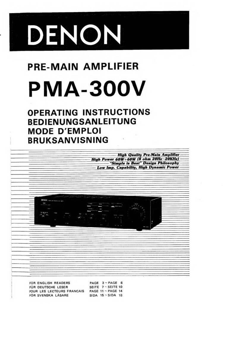
Denon PMA-50 User manual

Denon

Denon PMA-50 User manual

Denon PMA-2000IVR User manual

Denon

Denon PMA-2000IVR User manual

Denon AVR-3310CI User manual

Denon

Denon AVR-3310CI User manual

Denon PMA-150H User manual

Denon

Denon PMA-150H User manual

Denon POA-S1 User manual

Denon

Denon POA-S1 User manual

Denon PMA-A100 User manual

Denon

Denon PMA-A100 User manual

Denon AVC-X8500HA User manual

Denon

Denon AVC-X8500HA User manual

Denon PMA-1700NE User manual

Denon

Denon PMA-1700NE User manual

Denon PMA-777 User manual

Denon

Denon PMA-777 User manual

Denon AVP-A1HD User manual

Denon

Denon AVP-A1HD User manual

Denon PMA-720AE User manual

Denon

Denon PMA-720AE User manual

Popular Amplifier manuals by other brands

AFFA AFPD-022 operating instructions

AFFA

AFFA AFPD-022 operating instructions

Bogen CC4021 Installation and use manual

Bogen

Bogen CC4021 Installation and use manual

Pioneer SA-508 operating instructions

Pioneer

Pioneer SA-508 operating instructions

Sonance Sonamp 875D SE Application note

Sonance

Sonance Sonamp 875D SE Application note

OBT OBT-7100 Reference manual

OBT

OBT OBT-7100 Reference manual

Lepai LP-168HA user manual

Lepai

Lepai LP-168HA user manual

Yaesu VL-1000 operating manual

Yaesu

Yaesu VL-1000 operating manual

Yamaha RX-V557 Service manual

Yamaha

Yamaha RX-V557 Service manual

Cell2 SDF104H Installation & operation manual

Cell2

Cell2 SDF104H Installation & operation manual

Yamaha AX-397 Service manual

Yamaha

Yamaha AX-397 Service manual

Chiayo iTour Operation manuals

Chiayo

Chiayo iTour Operation manuals

AXTON A1390 Installation & operating instructions

AXTON

AXTON A1390 Installation & operating instructions

Phil Jones Bass BIGHEAD PRO HA-2 owner's manual

Phil Jones Bass

Phil Jones Bass BIGHEAD PRO HA-2 owner's manual

Axxent AX-1121TS user manual

Axxent

Axxent AX-1121TS user manual

Alpine MRP-F600 owner's manual

Alpine

Alpine MRP-F600 owner's manual

Inline IN3252 Operation manual

Inline

Inline IN3252 Operation manual

Belcat BG-3TN user manual

Belcat

Belcat BG-3TN user manual

HP AR Operating and servicing manual

HP

HP AR Operating and servicing manual

manuals.online logo
manuals.online logoBrands
  • About & Mission
  • Contact us
  • Privacy Policy
  • Terms and Conditions

Copyright 2025 Manuals.Online. All Rights Reserved.