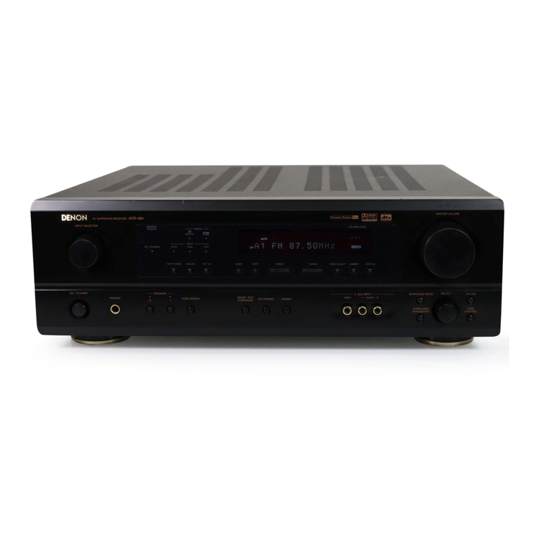
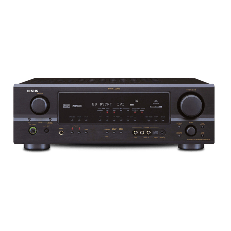
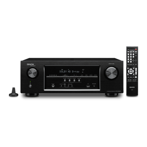
Denon AVR-589 User manual

AV SURROUND RECEIVER
AVR-589
Owner’s Manual

I
nSAFETY PRECAUTIONS
CAUTION
RISK OF ELECTRIC SHOCK
DO NOT OPEN
CAUTION:
TO REDUCETHE RISK OF ELECTRIC SHOCK, DO NOT REMOVE
COVER (OR BACK). NO USER-SERVICEABLE PARTS INSIDE.
REFER SERVICINGTO QUALIFIED SERVICE PERSONNEL.
The lightning flash with arrowhead symbol, within an equilateral
triangle, is intended to alert the user to the presence of
uninsulated “dangerous voltage” within the product’s enclosure
that may be of sufficient magnitude to constitute a risk of electric
shock to persons.
The exclamation point within an equilateral triangle is intended
to alert the user to the presence of important operating
and maintenance (servicing) instructions in the literature
accompanying the appliance.
WARNING:
TO REDUCE THE RISK OF FIRE OR ELECTRIC SHOCK, DO NOT
EXPOSE THIS APPLIANCE TO RAIN OR MOISTURE.
CAUTION:
To completely disconnect this product from the mains, disconnect
the plug from the wall socket outlet.
The mains plug is used to completely interrupt the power supply to
the unit and must be within easy access by the user.
DECLARATION OF CONFORMITY
We declare under our sole responsibility that this product, to which this
declaration relates, is in conformity with the following standards:
EN60065, EN55013, EN55020, EN61000-3-2 and EN61000-3-3.
Following the provisions of 2006/95/EC and 2004/108/EC Directive.
CAUTION:
• The ventilation should not be impeded by covering the ventilation openings with items, such as newspapers, tablecloths, curtains, etc.
• No naked flame sources, such as lighted candles, should be placed on the unit.
• Observe and follow local regulations regarding battery disposal.
• Do not expose the unit to dripping or splashing fluids.
• Do not place objects filled with liquids, such as vases, on the unit.
• Avoid high temperatures.
Allow for sufficient heat dispersion when installed in a rack.
• Handle the power cord carefully.
Hold the plug when unplugging the cord.
• Keep the unit free from moisture, water, and dust.
• Unplug the power cord when not using the unit for long
periods of time.
* (For apparatuses with ventilation holes)
• Do not obstruct the ventilation holes.
• Do not let foreign objects into the unit.
• Do not let insecticides, benzene, and thinner come in
contact with the unit.
• Never disassemble or modify the unit in any way.
nNOTE ON USE
A NOTE ABOUT RECYCLING:
This product’s packaging materials are recyclable and can be reused. Please dispose of any materials in accordance with the local recycling
regulations.
When discarding the unit, comply with local rules or regulations.
Batteries should never be thrown away or incinerated but disposed of in accordance with the local regulations concerning battery disposal.
This product and the supplied accessories, excluding the batteries, constitute the applicable product according to the WEEE directive.

Accessories ·····················································································2
Cautions on Handling·····································································3
Cautions on Installation·································································3
About the Remote Control Unit····················································3
Inserting the Batteries ···································································3
Operating Range of the Remote Control Unit································ 3
Part Names and Functions ····························································4
Front Panel····················································································· 4
Display ···························································································4
Rear Panel······················································································ 5
Remote Control Unit ······································································ 6
Preparations····················································································7
Cables Used for Connections ························································7
Speaker Connections ·····································································8
Speaker Installation········································································ 8
Speaker Connections ····································································· 8
Connecting Equipment with HDMI Connectors ··························9
Connecting the Monitor······························································· 10
Connecting the Playback Components ······································ 10
DVD Player··················································································· 10
CD Player ·····················································································11
iPod®····························································································11
TV/CABLE Tuner ··········································································11
Connecting the Recording Components ····································12
Video Cassette Recorder ····························································· 12
CD Recorder / MD Recorder / Tape Deck····································12
Connections to Other Devices·····················································12
Video Camera / Game Console ···················································· 12
Component with Multi-channel Output Connectors ····················13
Antenna Terminals ······································································13
Connecting the Power Cord ························································ 14
Once Connections are Completed ·············································· 14
Menu Map ·····················································································14
Examples of Front Display···························································14
qStandard Playback···································································23
Surround Playback of 2-channel Sources·····································23
Playing Multi-channel Sources (Dolby Digital, DTS, etc.) ·············24
wDSP Simulation Playback························································24
eDirect Playback·········································································24
rStereo Playback ·······································································24
Getting Started
Connections
Operations
Preparations··················································································15
Auto Setup···················································································· 16
aAuto Setup ·············································································· 16
sError Messages······································································· 17
System Setup Operation ····························································· 18
Example of Display of Default Values ········································ 18
1. Speaker Setup ·········································································· 19
a~ f Speaker Configuration····················································· 19
gSubwoofer Mode Setup·························································· 19
h~ A1 Distance ·········································································· 19
A2 ~ A6 Crossover Frequency ······················································20
A7 Test Tone················································································20
A8 Restore ·················································································· 20
2. Input Setup ··············································································· 21
a, sHDMI In Assign ·································································21
d~ hDigital In Assign ······························································21
jiPod Assign ·············································································21
kAudio Delay·············································································21
lEXT. IN Subwoofer Level························································21
A0 Auto Preset Memory ······························································22
3. Option Setup·············································································22
a~ dVolume Control ······························································· 22
fAuto Surround Mode ······························································ 22
gDirect Mode Setup··································································22
hRemote ID Setup ····································································23
Auto Setup
System Setup
Surround Modes
Adjusting the Parameters ····························································25
Surround Parameter·····································································25
aMode·······················································································26
sCinema EQ··············································································26
dD. Comp (Dynamic Range Compression) ·······························26
fLFE··························································································26
gCenter Image ··········································································26
hPanorama················································································26
jDimension···············································································26
kCenter Width···········································································26
lDelay Time··············································································26
A0 Effect Level·············································································26
A1 Room Size···············································································26
A2 SW ATT (Subwoofer Attenuation)···········································27
A3 Subwoofer ··············································································27
A4 Tone Control ···········································································27
A5 Bass ························································································27
A6 Treble······················································································27
A7 MultEQ····················································································27
A8 Dynamic EQ············································································27
A9 Dynamic Volume·····································································28
S0 DV Setting (Dynamic Volume Setting) ····································28
S1 RESTORER ·············································································28
S2 Night Mode·············································································29
S3 Default ····················································································29
Parameter
Information········································································ 29
nContents
Connections Setup Playback Remote Control Information Troubleshooting Specifications
Other Operations··········································································34
Recording on an External Device (REC OUT mode) ···················· 34
Convenient Functions ··································································34
Channel Level ··············································································34
Quick Select Function ·································································· 35
Personal Memory Plus Function ·················································· 35
Last Function Memory································································· 35
Backup Memory···········································································35
Resetting the Microprocessor ····················································· 35
Operating DENON Audio Components ······································36
Presetting······················································································36
Operating Preset Components····················································36
Punch Through Function ·····························································38
Other Operations and Functions
Remote Control Unit Operations
Other Information························································· 39
Troubleshooting····························································· 44
Specifications·································································· 46
List of preset codes··························· End of this manual
Getting Started
Check that the following parts are supplied with the product.
qOwner’s manual ...................................................................... 1
wGetting started ........................................................................ 1
ePower cord (Cord length: Approx. 1.7 m)................................ 1
rService station list ................................................................... 1
tRemote control (RC-1104)........................................................ 1
yR6/AA batteries ....................................................................... 2
uFM indoor antenna .................................................................. 1
iAM loop antenna ..................................................................... 1
oSetup microphone
(DM-A409, Cord length: Approx. 7.6 m).................................. 1
e t
o
ui
Thank you for purchasing this DENON product. To ensure proper
operation, please read this owner’s manual carefully before using the
product.
After reading them, be sure to keep them for future reference.
Getting Started
Accessories
Preparations··················································································30
Turning the Power On··································································30
Selecting the Input Source···························································30
Setting the Input Mode································································ 30
Operations During Playback·························································30
Playing Video and Audio Equipment··········································31
Basic Operation············································································31
Listening to FM/AM Broadcasts ················································· 31
Basic Operation············································································31
Presetting Radio Stations (Preset Memory)································· 31
Listening to Preset Stations·························································32
iPod®Playback·············································································32
Preparations ·················································································32
Listening to Audio ········································································ 33
Viewing Still Pictures or Videos on the iPod ································33
Playback

Connections Setup Playback Remote Control Information Troubleshooting Specifications
In addition to the AVR-589, the included remote control unit (RC-1104)
can also be used to operate the equipment listed below.
q DENON system components
w Non-DENON system components
• By setting the preset memory (vpage 36 ~ 38)
Inserting the Batteries
NOTE
• Replace the batteries with new ones if the set does not operate
even when the remote control unit is operated close to the unit.
• The supplied batteries are only for verifying operation.
• When inserting the batteries, be sure to do so in the proper direction,
following the “q” and “w” marks in the battery compartment.
• To prevent damage or leakage of battery fluid:
• Do not use a new battery together with an old one.
• Do not use two different types of batteries.
• Do not attempt to charge dry batteries.
• Do not short-circuit, disassemble, heat or dispose of batteries in
flames.
• If the battery fluid should leak, carefully wipe the fluid off the inside
of the battery compartment and insert new batteries.
• Remove the batteries from the remote control unit if it will not be in
use for long periods.
• When replacing the batteries, have the new batteries ready and
insert them as quickly as possible.
30°
30°
Approx. 7 m
Operating Range of the Remote Control
Unit
Point the remote control unit at the remote sensor when operating it.
NOTE
The set may function improperly or the remote control unit may not
operate if the remote control sensor is exposed to direct sunlight,
strong artificial light from an inverter type fluorescent lamp or infrared
light.
About the Remote Control Unit
Getting Started
qLift the clasp and remove the rear cover.
ePut the rear cover back on.
R6/AA
wLoad the two batteries properly as indicated
by the marks in the battery compartment.
• Before turning the power switch on
Check once again that all connections are correct and that there are
no problems with the connection cables.
• Power is supplied to some of the circuitry even when the unit is
set to the standby mode. When traveling or leaving home for long
periods of time, be sure to unplug the power cord from the power
outlet.
• About condensation
If there is a major difference in temperature between the inside of
the unit and the surroundings, condensation (dew) may form on
the operating parts inside the unit, causing the unit not to operate
properly.
If this happens, let the unit sit for an hour or two with the power
turned off and wait until there is little difference in temperature
before using the unit.
• Cautions on using mobile phones
Using a mobile phone near this unit may result in noise. If so, move
the mobile phone away from this unit when it is in use.
• Moving the unit
Turn off the power and unplug the power cord from the power
outlet.
Next, disconnect the connection cables to other system units before
moving the unit.
• Note that the illustrations in these instructions may differ from the
actual unit for explanation purposes.
Note:
For proper heat dispersal, do not install this unit in a confined
space, such as a bookcase or similar enclosure.
bNote
bWall
b
b
Cautions on Handling
Cautions on Installation

Connections Setup Playback Remote Control Information Troubleshooting Specifications
For buttons not explained here, see the page indicated in parentheses ( ).
wery ot
Q4W4 W3W5 W2 W1 W0 Q7Q6 Q5
q Q0 Q1 Q2u i Q3
Q8
Q9
W6 W7 E0 E3 E4 E5E1 E2
W8 W9
qPower operation button
(ON/STANDBY) ·········································· (30)
wPower indicator ·········································· (30)
ePower switch (hON jOFF) ··············· (30, 35)
rHeadphone jack (PHONES)························ (31)
tINPUT MODE button·································· (30)
ySPEAKERS button ································ (31, 35)
uQUICK SELECT buttons ····························· (35)
iV. AUX INPUT connectors
Remove the cap covering the connectors when
you want to use them.
oSETUP MIC jack ·········································· (15)
Q0 SYSTEM SETUP button ····························· (18)
Q1 SURR. MODE / SURR. PARA button ·· (23, 25)
Q2 SELECT/ENTER knob
Front Panel
q
y t r
w e
qSignal channel indicator
Lights when the preset channel is displayed at
w.
wInformation display
eInput signal indicators
rMaster volume indicator
This displays the volume level.
The Setup item number is displayed in System
Setup.
tRecording output source indicator
This lights when the REC OUT mode is
selected. (This indicator is off when “SOURCE”
is selected.)
yTuner reception mode indicators
These light according to the reception conditions
when the input source is set to “TUNER”.
• AUTO
This lights when in the auto tuning mode.
• STEREO
In the FM mode, this lights when receiving
analog stereo broadcasts.
• TUNED
This lights when the broadcast is properly tuned
in.
Display
• The SELECT/ENTER knob on the main unit
operates in the same way as the cursor oand p
buttons on the remote control unit.
• The control functions in the same way as the
cursor obutton when turned counterclockwise,
as the cursor pbutton when turned clockwise.
• The control functions in the same way as the
ENTER button when pressed the knob.
E4 DYNAMIC VOLUME button··················(27, 28)
bAbout Dynamic Volume
Audyssey Dynamic Volume™ solves the problem
of large variations in volume level between
television programs, commercials, and between
the soft and loud passages of movies.
Audyssey Dynamic EQ™ is integrated into
Dynamic Volume so that as the playback volume
is adjusted automatically, the perceived bass
response, tonal balance, surround impression,
and dialog clarity remain the same.
bAbout Dynamic EQ
Audyssey Dynamic EQ solves the problem of
deteriorating sound quality as volume is decreased
by taking into account human perception and
room acoustics. Audyssey Dynamic EQ works in
tandem with Audyssey MultEQ®to provide well-
balanced sound for every listener at any volume
level.
E5 VIDEO SELECT button ······························· (31)
Q3 Cursor buttons (ui)································· (18)
Q4 MASTER VOLUME control knob··············· (30)
Q5 Dynamic Volume indicator························ (28)
Q6 MultEQ indicator ········································ (27)
Q7 Master volume indicator
Q8 INPUT mode indicators······························ (30)
Q9 SIGNAL indicators
W0 Display
W1 SPEAKERS indicators································· (31)
W2 Remote control sensor ································ (3)
W3 REC SELECT button ··································· (34)
W4 SOURCE SELECT knob ······························ (30)
W5 SOURCE button·········································· (30)
W6 STATUS button ·········································· (29)
W7 DIMMER button·········································· (31)
W8 RESTORER button······································ (28)
W9 BAND button ·············································· (31)
E0 SHIFT button··············································· (31)
E1 PRESET CHANNEL buttons (df)·············· (31)
E2 TUNING buttons (df)································ (31)
E3 MULTEQ button ········································· (27)
Part Names and Functions
Getting Started

Connections Setup Playback Remote Control Information Troubleshooting Specifications
yiQ0 uo
Q1
qwt
e r
Rear Panel
Getting Started
qDigital audio connectors
(OPTICAL / COAXIAL) ·························· (9 ~ 11)
wVIDEO / S-VIDEO connectors············ (10 ~ 12)
eAnalog audio connectors
(AUDIO) ·················································(9 ~ 12)
rEXT. IN connectors····································· (13)
tPRE OUT connector······································ (8)
yAC inlet (AC IN)··········································· (14)
uSpeaker terminals (SPEAKERS) ·················· (8)
iFM/AM antenna terminals
(TUNER ANTENNA)···································· (13)
oCOMPONENT VIDEO connectors·········(10, 11)
Q0 HDMI connectors·································· (9 ~ 11)
Q1 DOCK CONTROL jack ··································(11)

Connections Setup Playback Remote Control Information Troubleshooting Specifications
Remote Control Unit
q
y
u
i
o
w
e
r
t
Q0
Q2
Q3
Q4
Q5
Q6
Q1
qIndicator ······················································ (36)
wPower buttons ············································ (30)
eQUICK SELECT buttons ····························· (35)
rSource select buttons ································ (30)
tSystem buttons ···································· (33, 37)
yAUDIO DELAY button ································ (21)
uCursor buttons (uio p)························· (18)
iDYNAMIC VOLUME button··················(27, 28)
oRESTORER button······································ (28)
Q0 SOURCE CONTROL switches···················· (31)
Q1 Remote control signal transmitter
Q2 Master volume control buttons ················ (30)
Q3 MUTING button·········································· (31)
Q4 NIGHT button ············································· (29)
Q5 MULTEQ button ········································· (27)
Q6 Channel select /
ENTER button ······································· (18, 34)
q
r
w
t
y
i
Q1
Q0
u
o
e
qPower buttons ······································ (36, 38)
wSource select buttons ································ (30)
eVideo select button···································· (31)
rTuner system buttons·························· (31, 32)
tTest tone button········································· (20)
ySurround mode buttons ················ (23, 24, 26)
uSystem setup button ································· (18)
iSurround parameter button················ (23, 25)
oEnter button················································ (18)
Q0 Input mode button ····································· (30)
Q1 Cursor buttons (uio p)························· (18)
NOTE
• The SAT TU button cannot be used.
• If buttons on the front or rear are pressed strongly, the button on the opposite side will be activated too.
[ Front ] [ Rear ]
Getting Started

Getting Started Setup Playback Remote Control Information Troubleshooting Specifications
Audio cables Video cables
Coaxial digital connections
(Orange)
Coaxial digital (75 Ω/ohms pin-plug) cable
Optical digital connections
Optical cable
Analog connections (stereo)
(White)
(Red)
R
L
R
L
Stereo pin-plug cable
Analog connections (monaural, for subwoofer)
(Black)
Pin-plug cable
Speaker connections
Speaker cables
Component video connections
(Green)
(Blue)
(Red)
(Y)
(PB/CB)
(PR/CR)
Component video cable
S-Video connections
S-Video cable
Video connections
(Yellow)
75 Ω/ohms pin-plug video cable
Audio and video cables
HDMI connections
19-pin HDMI cable
Signal direction
Audio signal: Video signal:
Output
Input
Input
Output
Output
Input
Input
Output
Cables Used for Connections
Select the cables according to the equipment being connected.
Preparations
Connections
NOTE
• Do not plug in the power cord until all connections have been
completed.
• When making connections, also refer to the operating instructions of
the other components.
• Be sure to connect the left and right channels properly (left with left,
right with right).
• Do not bundle power cords together with connection cables. Doing
so can result in humming or noise.
Connections for all compatible audio and video signal formats
are described in this owner’s manual. Please select the types of
connections suited for the equipment you are connecting.
With some types of connections, certain settings must be made
on the AVR-589. For details, refer to the instructions for the
respective connection items below.
Connections

Getting Started Setup Playback Remote Control Information Troubleshooting Specifications
The illustration below shows a basic example of installation of the amplifier combined with 6 speakers and
a monitor.
Speaker Installation
Subwoofer Center speaker
Surround speakers
Front speakers
Place the front speakers to the
sides of the monitor or screen and
as flush with the screen surface as
possible.
The table below shows a typical speaker configuration for the AVR-589.
FRONT CENTER SURROUND SUBWOOFER
L R L R
5.1-channels S S S S S S
3.1-channels S S S – – S
2.1-channels S S – – – S
2-channels S S – – – –
Speaker Connections
Connections
w q w q
w q w q
*/
w q
(R)
(L) (R)
(L)
Speaker Connections
Example: 5.1-channels
Front speakers
ACenter speakerSubwoofer
Subwoofer
with built-in
amplifier
bL : Left
R : Right
Surround speakers

Getting Started Connections Setup Playback Remote Control Information Troubleshooting Specifications
Connecting the Speaker Cables
Carefully check the left (L) and right (R) channels and + (red) and –
(black) polarities on the speakers being connected to the AVR-589,
and be sure to interconnect the channels and polarities correctly.
1Peel off about 10 mm of sheathing from the
tip of the speaker cable, then either twist the
core wire tightly or terminate it.
2Turn the speaker terminal counterclockwise
to loosen it.
3Insert the speaker cable’s core wire to the
hilt into the speaker terminal.
4Turn the speaker terminal clockwise to
tighten it.
NOTE
• Use speakers with an impedance of 6 to 16 Ω/ohms. When using
front A and B speakers simultaneously, use speakers with an
impedance of 12 to 16 Ω/ohms.
• Connect the speaker cables in such a way that they do not stick out
of the speaker terminals. The protection circuit may be activated if
the core wires touch the rear panel or if the + and – sides touch each
other (v“Protection circuit”).
• Never touch the speaker terminals while the power supply is
connected. Doing so could result in electric shock.
Protection circuit
If the core wires touch the rear panel and the screws etc., or the ±
sides touch each other, the protection circuit will be activated and
the power indicator will flash red at intervals of 0.5 secs.
If the protection circuit is activated, the speaker output is isolated,
and the power supply goes to the standby state. If the power sup-
ply is turned off, after the power cord is withdrawn, please confirm
that speaker cable and input cable are connected.
Also, if replaying large sound levels by using a speaker having an
impedance less than that specified (eg, 4 Ω/ohms), the temperature
will rise, and the protection circuit might be activated. The power
supply will go into the standby state, and the power indicator will
flash red at 2 second intervals.
In this case, please switch off the power supply, and wait until the
AVR-589 has cooled down, and the surrounding ventilation is good.
Even if there are no problems with the surrounding ventilation and
connections, in the event of the protection circuit becoming acti-
vated, due to thinking that the AVR-589 has failed, please contact
DENON Service center after switching off.
Connections
065
)%.*
*/
)%.*
"6%*0
"6%*0
3-
065 065
$0"9*"-
R
L
R
L
MonitorDVD player
bThe AVR-589 is equipped for HDMI version 1.3a. This version
is compatible with other versions, allowing connection to all
components equipped with an HDMI connector.
bThe AVR-589 is compatible with 30- and 36-bit Deep Color.
bThe AVR-589 can be connected to a device equipped with an HDMI
output connector using an HDMI cable.
bThe AVR-589 is compatible with HDMI Ver. 1.3a Deep Color and
xvYCC.
• The audio and video signals input to the AVR-589’s HDMI input
connector are output unchanged from the HDMI output connector.
Because of this, the sound is output from the monitor connected
using the HDMI connectors, but in order to take full advantage of the
AVR-589’s playback sound, turn the TV’s volume down.
• If the connected monitor or DVD player only has a DVI-D connector,
use an HDMI/DVI converter cable. When using a DVI cable, no
audio signals are transmitted.
• Use a Deep Color compatible cable for connection to Deep Color
compatible devices.
When connecting with an HDMI/DVI converter cable
(adapter)
• HDMI video signals are theoretically compatible with the DVI
format.
When connecting to a monitor, etc., equipped with a DVI-D
connector, connection is possible using an HDMI/DVI converter
cable, but depending on the combination of components in some
cases the video signals will not be output.
• When connecting using an HDMI/DVI converter adapter, the video
signals may not be output properly due to poor connections with
the connected cable, etc.
NOTE
• The AVR-589 cannot be controlled from another device via the HDMI
cable.
• Video signals are not output if the input video signals do not match
the monitor’s resolution. In this case, switch the DVD player’s
resolution to a resolution with which the monitor is compatible.
• Use a cable on which the HDMI logo is indicated (a certified HDMI
product) for connection to the HDMI connector. Normal playback
may not be possible when using a cable other than one on which the
HDMI logo is indicated (a non-HDMI-certified product).
• If the monitor or DVD player does not support Deep Color, deep
color signal transfer is not possible.
• If the monitor or DVD player does not support xvYCC, xvYCC signal
transfer is not possible.
When HDMI input signals are sent to the monitor as HDMI output,
both video and audio are output to the monitor.
Connecting Equipment with HDMI Connectors
NOTE
The audio signal input to the HDMI input connector cannot be
played on the AVR-589. Input the audio signal to the digital audio
input connector or analog audio input connector.

47*%&0
065
"6%*0 7*%&0
$0.10/&/57*%&0
: 1#13
7*%&0
065065
"6%*0
3-
065 065
)%.*
065
$0"9*"-
R
L
R
L
Select the terminal to use and connect the device.
47*%&0
*/
7*%&0
$0.10/&/57*%&0
: 1#13
7*%&0
*/
)%.*
*/ */
Monitor
Connecting the Monitor
NOTE
• The AVR-589 supports four video input formats:
HDMI, component video, S-video and video.
Because video signals are output from the
AVR-589’s monitor output terminal in the same
format as the video input signals, the monitor
output terminal should be of the same type
as the terminal used for input.
• The component video connectors may
be indicated differently on your monitor.
For details, see the monitor’s operating
instructions.
• To play the sound by AVR-589, make analog or
digital audio output connections to AVR-589’s
audio input connectors.
GFlow of video signals inside the AVR-589H
High picture
quality playback HDMI connector
Component video
connectors
S-Video connector
Video connector
Monitor
HDMI connector
Component video
connectors
S-Video connector
Video connector
Video input terminals Monitor output
terminals
Carefully check the left (L) and right (R) channels and the inputs and outputs, and be sure to interconnect
correctly.
Connecting the Playback Components
DVD Player
Select the terminal to use and connect the device.
DVD player
• The same method can be used to connect an HDP (High-Definition Player) such as a Blu-ray Disc
player.
• When using an optical cable for the digital audio connection, make the settings at “System Setup”
– “Input Setup” – “Digital In Assign” (vpage 21).
NOTE
The audio signal input to
the HDMI input connector
cannot be played on the
AVR-589. Input the audio
signal to the digital audio
input connector or analog
audio input connector.
NOTE
Because video signals are output from the AVR-589’s monitor output terminal in the same format as the
video input signals, the monitor output terminal should be of the same type as the terminal used for
input.
0
Getting Started Connections Setup Playback Remote Control Information Troubleshooting Specifications

"6%*0
"6%*0
3-
065065
$0"9*"-
R
L
R
L
CD Player
Select the terminal to use and connect the device.
CD player
When using an optical cable for the digital audio connection, make
the settings at “System Setup” – “Input Setup” – “Digital In
Assign” (vpage 21).
iPod®
"4%/8
RL
RL
iPod
• With the default settings, the iPod can be used connected to the
VCR (iPod) connector.
• To assign the iPod to a connector other than VCR (iPod), make
the settings at “System Setup” – “Input Setup” – “iPod Assign”
(vpage 21).
Use a DENON control dock for iPod (ASD-1R, ASD-3N or ASD-3W,
sold separately) to connect the iPod to the AVR-589. For instructions
on the control dock for iPod settings, refer to the control dock for
iPod’s operating instructions.
NOTE
To playback iPod Video or Photos on a TV monitor, connect
the TV to the S-Video Out terminal of AVR-589.
47*%&0
065
"6%*0 7*%&0
$0.10/&/57*%&0
: 1#13
7*%&0
065065
"6%*0
3-
065 065
)%.*
015*$"-
065
R
L
R
L
TV/CABLE Tuner
Select the terminal to use and connect the device.
TV tuner
When using a coaxial cable for the digital audio connection, make the settings
at “System Setup” – “Input Setup” – “Digital In Assign” (vpage 21).
NOTE
The audio signal input to the HDMI input connector cannot be
played on the AVR-589. Input the audio signal to the digital audio input
connector or analog audio input connector.
NOTE
Because video signals are output from the AVR-589’s monitor output terminal
in the same format as the video input signals, the monitor output terminal
should be of the same type as the terminal used for input.
Getting Started Connections Setup Playback Remote Control Information Troubleshooting Specifications

Getting Started Setup Playback Remote Control Information Troubleshooting Specifications
Carefully check the left (L) and right (R) channels and the inputs and outputs, and be sure to interconnect correctly.
Video Cassette Recorder
Select the terminal to use and connect the device.
When recording via the AVR-589, the playback device’s cable must
be of the same type as the cable used to connect the AVR-589’s VCR
OUT connector.
Example: TV IN →S-Video cable : VCR OUT →S-Video cable
TV IN →Video cable : VCR OUT →Video cable
Connecting the Recording Components
47*%&047*%&0
065
3-3-
065065*/
"6%*07*%&0"6%*0 7*%&0
*/
"6%*0"6%*0 7*%&0 7*%&0
*/
R
L
R
L
R
L
R
L
Video cassette recorder
3- 3-
*/ 065
"6%*0"6%*0
"6%*0
R
L
R
L
R
L
R
L
CD Recorder / MD Recorder / Tape Deck
Select the terminal to use and connect the device.
CD recorder /
MD recorder /
Tape deck
Connections
Video Camera / Game Console
065
"6%*07*%&0
7*%&0 "6%*0
3-
065
R
L
R
L
Video camera /
Game console
Carefully check the left (L) and right (R) channels and the inputs and
outputs, and be sure to interconnect correctly.
Select the terminal to use and connect the device.
Connections to Other Devices

Getting Started Setup Playback Remote Control Information Troubleshooting Specifications
Component with Multi-channel Output
Connectors
46#
800'&3
$&/5&3 463306/%
3-
'30/5
3-
"6%*0
R
L
R
L
R
L
R
L
DVD player / External decoder
• To play the analog input signals input to the EXT. IN connectors,
press the INPUT MODE button on the main unit or the INPUT button
on the remote control unit and select “EXT. IN” (vpage 30).
• The video signal can be connected in the same way as a DVD player
(vpage 10).
• To play copyright-protected discs, connect the AVR-589’s EXT.
IN connector with the DVD player’s analog multi-channel output
connector.
Select the terminal to use and connect the device.
Antenna Terminals
An FM antenna cable plug can be connected directly.
Direction of broadcasting station
AM loop antenna
(supplied)
FM antenna
75 Ω/ohms
Coaxial cable
FM indoor
antenna
(supplied)
Ground
AM outdoor
antenna
Connections
NOTE
• Do not connect two FM antennas simultaneously.
• Even if an external AM antenna is used, do not disconnect the AM
loop antenna.
• Make sure the AM loop antenna lead terminals do not touch metal
parts of the panel.
nAM loop antenna assembly
Remove the vinyl tie and take out
the connection line.
Bend in the reverse direction.
a. With the antenna on top of any
stable surface.
Mount b. With the antenna attached to a
wall.
Installation hole Mount
on wall, etc.
Connection of AM antennas
1. Push the lever. 2. Insert the conductor. 3. Return the lever.

Wait until all connections have been completed before connecting the
power cord.
Connecting the Power Cord
NOTE
Insert the AC plugs securely. Incomplete connections could cause
noise.
To household
power outlet
Power cord
(supplied)
Turning the Power On (vpage 30)
Once Connections are
Completed
Getting Started Connections Setup Playback Remote Control Multi-Zone Troubleshooting Specifications
Auto Setup (vpage 15 ~ 17)
nAuto Setup
• Step 1: Speaker Detection
• Step 2: Measurement
• Step 3: Calculation
• Step 4: Check
• Step 5: Store
System Setup (vpage 18 ~ 23)
nSpeaker Setup (vpage 19, 20)
• Speaker Configuration
• Subwoofer Mode Setup
• Distance
• Crossover Frequency
• Test Tone
• Restore
nInput Setup (vpage 21, 22)
• HDMI In Assign
• Digital In Assign
• iPod Assign
• Audio Delay
• EXT. IN Subwoofer Level
• Auto Preset Memory
nOption Setup
(vpage 22, 23)
• Volume Control
· Volume Limit
· Power On Level
· Mute Level
• Auto Surround Mode
• Direct Mode Setup
• Remote ID Setup
bWhen the setup microphone is connected.
Parameter (vpage 25 ~ 29)
nSurround Parameter
• Mode
• Cinema EQ
• D. Comp
• LFE
• Center Image
• Panorama
• Dimension
• Center Width
• Delay Time
• Effect Level
• Room Size
• SW ATT
• Subwoofer
• Tone Control
• Bass
• Treble
• MultEQ
• Dynamic EQ
• Dynamic Volume
• DV Setting
• RESTORER
• Night Mode
• Default
Information (vpage 29)
nStatus nAudio Input Signal
Menu Map
Operations
Q
17 T.Tone Yes<
Press the obutton to select.
Currently selected line
Some typical examples are described below.
W
1 HDMI1:DVD
Item number
Current setting
Currently selected line
Menu number
Examples of Front Display

<SPEAKERS>
MASTER VOLUME
ui
ENTER, o
Preparations
• Audyssey MultEQ automatically measures the acoustical problems
in the listening environment to create the best audio experience for
your home theater.
• Audyssey MultEQ optimizes a large listening area where one or
more listeners are seated.
Measurements are performed by placing the calibrated microphone
(DM-A409) successively at multiple positions throughout the
listening area as shown in Example q. For best results, it is strongly
recommended to measure 6 positions so that the measurements
have the proper spatial weighting.
Even if the listening environment is small as shown in Example w,
measuring at multiple points throughout the listening environment
results in more effective correction.
To make manual adjustments to the settings, see pages 19, 20.
About the main listening position (*M)
The main listening position refers to the most central position where
one would normally sit within the listening environment.
MultEQ uses the measurements from this position to calculate
speaker distance, level, polarity, and the optimum crossover value
for the subwoofer.
*M
*M
Example qExample w
( :Measuring positions)
1Press <SPEAKERS> to select the front speakers Front
A, Front B or Front A+B.
2Connect the included calibrated setup microphone to
the SETUP MIC jack on the main unit.
“Auto Set<Start” is displayed.
3Place the microphone at ear height on a tripod or stand
with the microphone pointing directly up towards the
ceiling.
bDo not hold the microphone in your hand during measurements.
Be sure that the path from microphone to the speakers is not
blocked by objects. Avoid placing the microphone close to a seat
back or wall as sound reflections may give inaccurate results.
Sound
receptor
Setup
microphone
Button located on both the main unit and the remote control
unit BUTTON
Button only on the main unit <BUTTON>
Button only on the remote control unit [BUTTON]
Symbols used to indicate buttons in this manual
When using a subwoofer, make the following settings before starting
the auto setup procedure:
• Defeat the volume and crossover controls if possible
• If this is not possible then set
• Volume: “12 o’clock” position
• Crossover frequency: “Maximum/Highest Frequency”
• Low pass filter: “Off”
• Standby mode: “Off”
Auto Setup
SETUP MIC jack
Getting Started Connections Setup Playback Remote Control Information Troubleshooting Specifications
ENTER
[SOURCE
CONTROL 1]
MASTER
VOLUME
uio
uio
ENTER
[Front] [Rear]

About the Auto Setup
The Audyssey MultEQ auto setup function detects the presence of
each speaker and automatically calculates the speaker size, channel
level, distance, and optimal crossover frequency setting. Audyssey
MultEQ corrects acoustical distortions within the listening area.
Before starting, connect and position all of your speakers.
Once started, MultEQ will play a series of test tones through each
speaker.
NOTE
Do not change the speaker connections or subwoofer volume after
“Step 1”.
If an error message appears during the measurements, check “Error
Messages”, take the advised action, then start the measurements
again (vpage 17).
The speaker connection and polarity are detected at the first
measurement position (main listening position). The following
attributes are also determined at this time: “Speaker Size”, “Speaker
Distance”, “Channel Level”, “Crossover Frequency”.
q Press owhile “Auto Set<Start” is displayed.
b To operate from the remote control unit, be sure to set the
[SOURCE CONTROL 1] to “AUDIO”.
• While the measurements are being conducted “Measure:FL
<Ccl” (“FL” indicates the speaker being measured) is displayed.
• When the measurements are completed, the number of detected
speakers is displayed.
Example : For a 5.1 channel speaker configuration
Speaker:3/2/.1
Step 1 : Speaker Detection
• If the result differs from the actual connection status or an error
message appears, use ito display “Retry<” and then press oto
repeat the measurement.
• If the result still differs from the actual connection status after
re-measurement or the error message still appears, it is possible
that the speakers are not connected properly. Turn the AVR-589
off, check the speaker connections and repeat the measurement
process from the beginning.
Number of front speakers or
center speakers
aAuto Setup
The settings found at this stage are applied automatically.
GAuto setup flowH
Step 1: Speaker Detection
Step 2: Measurement
Step 3: Calculation
Step 4: Check
Step 5: Store
Step 2 : Measurement
q Press ito select “2nd Start<”, then press o.
• The measurement of the 2nd position starts.
w Move the microphone to the 3rd position and press o.
• The measurement of the 3rd position starts.
e Perform wrepeatedly.
• “Calculate<” is displayed when you have completed
measurements in 6 positions.
• If you want to stop after measuring just five or fewer positions,
use ito display “Calculate<”.
After completing a measurement position, move the microphone to
the next position.
Measure at 6 positions: the main listening position and 5 other
surrounding positions. Although it is allowable to measure less than 6
positions, it is recommended to measure 6for best results.
NOTE
• Do not disconnect the setup microphone until the auto setup
procedure is completed.
• When using headphones, unplug the headphones before starting
the auto setup procedure.
NOTE
• Loud test sounds may be played during Audyssey MultEQ automatic
speaker setup. This is part of normal operation. If there is background
noise in room, these test signals will increase in volume.
• Do not stand between the speakers and setup microphone or allow
obstacles in the path while the measurements are being made. This
will cause inaccurate readings.
• Make the room as quiet as possible. Background noise can disrupt
the room measurements. Close windows, silence cell phones,
televisions, radios, air conditioners, fluorescent lights, home
appliances, light dimmers, or other devices as measurements may
be affected by these sounds.
Cell phones should be placed away from all audio electronics during
the measurement process as Radio Frequency Interference (RFI)
may cause measurement disruptions (even if the cell phone is not in
use).
• Operating MASTER VOLUME during the measurements will cancel
the measurements.
• To cancel the measurements, press owhile “Measure:FL <Ccl”
is displayed (“Ccl” stands for “Cancel”).
Step 3 : Calculation
The values obtained from the measurements are automatically
analyzed and the attributes for each of the speakers in the listening
area are determined.
q Press owhile “Calculate” is displayed.
• “Calculating” is displayed and analysis begins.
• Analysis takes several minutes to complete.
• The time required for this analysis depends on the number of
speakers connected. The greater the number of speakers connected,
the longer analysis will take.
NOTE
Do not change the speaker connections or subwoofer volume,
or speaker locations after making measurements. If changes are
necessary, make the changes and use the Audyssey MultEQ auto
setup once again for an updated EQ solution.
Subwoofer
Yes: “.1”, No: “0”
Number of surround speakers
Auto Setup
Optimize settings for speakers in use.
Getting Started Connections Setup Playback Remote Control Information Troubleshooting Specifications

Step 4 : Check
• To proceed to “Step 5” without checking the analysis result, use ui to select “Store<”
while “Parameter Check<” is displayed.
• Values that are different from the actual distance may be set for speakers with built-in filters
(subwoofers, etc). This is because filters add electrical delay to the signal that should be
compensated.
NOTE
Do not turn the power off while the settings are being stored.
Step 5 : Store
The auto setup measurement results are stored in the AVR-589.
q Press owhile “Store<” is displayed.
• “Storing” blinks on the display panel while the results are being stored.
• When storing is complete, “Completed” is displayed followed by “Disconnect Mic”.
w Disconnect the setup microphone from the AVR-589.
sError Messages
If the auto setup procedure could not be completed due to speaker installation, the measuring environment,
etc. an error message is displayed. Check the relevant items and be sure to take the necessary measures. After
addressing any issues, perform the auto setup procedure over again.
NOTE Be sure to turn the power off before checking speaker connections.
Select “Retry” to make the measurements again.
Error messages (examples) Cause Measures
Mic or Sp:None
• The included setup microphone is not
connected.
• Not all speakers could be detected.
• Connect the included setup
microphone to the SETUP MIC jack
on the main unit.
• Check the speaker connections.
Ambient Noise
• Too much noise in the room for
accurate measurements to be made.
• Speaker or subwoofer sound is too
low for accurate measurements to be
made.
• Either turn off any device generating
noise or move it away.
• Try again when the surroundings are
quieter.
• Check the speaker installation and the
direction in which the speakers are
facing.
• Adjust the subwoofer’s volume.
Caution:Sp None
The messages alternate
F R
• Displayed speaker could not be
detected.
· The front L and front R speakers
were not properly detected.
· Only one channel of the surround
speakers was detected.
• Check the connections of the
displayed speaker.
Caution:Phase
The messages alternate
S L
• Displayed speaker connected with
the polarities reversed.
• Check the polarities of the displayed
speaker.
• For some speakers, this error
message may be displayed even if
the speaker is properly connected. If
the connection is correct, use ui to
display “Skip<” and then press o.
nTo switch to another analysis result item
Press ENTER.
This returns you to analysis results items, so repeat operation q.
nTo proceed to “Step 5 : Store”
During display of crossover frequency result or analysis results item, press ENTER.
• “Store<” is displayed.
nTo cancel storing
Use ui to display “Cancel<” while “Store<” is displayed and press o.
• All the measured auto setup data will be erased.
When analysis is complete, “Parameter Check<” is displayed.
Press oand check the analysis results for the following four items.
q Make your selection using uiand press o.
• Presence and size of speaker
“SpConfig. Check<”
• Distance of speaker from listening position
“Distance Check<”
• Speaker channel level
“Ch Level Check<”
• Crossover Frequency
“Crossover Check<”
w Use ui to change which speaker is displayed.
Getting Started Connections Setup Playback Remote Control Information Troubleshooting Specifications

Make detail settings for various parameters.
1Press SYSTEM SETUP.
“System Setup” is displayed.
bTo operate from the remote control unit, be sure to set the
[SOURCE CONTROL 1] to “AUDIO”.
2Press ENTER.
Three setup menu categories are displayed.
“1. Sp” : Speaker Setup
“2. In” : Input Setup
“3. Op” : Option Setup
• The cursor of the item number selected blinks.
• For details of the items to be set in each item, see “Menu Map”
(vpage 14).
3Press opto select the item you want to set, then
press ENTER.
The detailed setup menu for each item is displayed.
4Press ui to select the item you want to change, then
press opto change the setting.
5Press ENTER or i to conrm the next settings.
2
1.Sp 2.In 3.Op
4
Q
1 Front :Large
1
*System Setup
Q
Speaker Setup
3
[Selectable items] Large Small
In lists of selectable items or adjustable ranges, the item
surrounded by a border is the default value.
ENTER
[AUDIO DELAY]
[SOURCE
CONTROL 1]
uio p
ui
ENTER, o p
SYSTEM SETUP
uiop
ENTER
SYSTEM
SETUP
[TEST]
[Front] [Rear]
Button located on both the main unit and the remote control
unit BUTTON
Button only on the main unit <BUTTON>
Button only on the remote control unit [BUTTON]
Symbols used to indicate buttons in this manual
nTo move to a setup item of another category
Press SYSTEM SETUP.
• Returns to the setup menu.
• Perform steps 3 and 4.
nTo exit setup
Press SYSTEM SETUP while the setup menu is displayed.
• The display returns to normal.
System Setup Operation
The same operation is possible on the main unit or remote control
unit.
System Setup
Example of Display of Default
Values
Getting Started Connections Setup Playback Remote Control Information Troubleshooting Specifications
Other manuals for AVR-589
3
Table of contents
Other Denon Stereo Receiver manuals

Denon
Denon AVR-3600 User manual

Denon
Denon AVR-X6800H User manual

Denon
Denon AVR-X2800H User manual

Denon
Denon AVR-1907 User manual

Denon
Denon AVR-E300P User manual

Denon
Denon AVR-2106 User manual

Denon
Denon AVR-1602 User manual

Denon
Denon AVRX1500HOM User manual

Denon
Denon AVR-1404 User manual

Denon
Denon AVR 4308CI - AV Network Receiver User guide

Denon
Denon AVR-2807 User manual

Denon
Denon AirPlay AVR-3311CI User manual

Denon
Denon AVR-E400P User manual

Denon
Denon AVR-1712 User guide

Denon
Denon AVR-1707 User manual

Denon
Denon S-5BD User manual

Denon
Denon AVR-S500BT User manual

Denon
Denon AVR-X7200W User manual

Denon
Denon DRA-700AE User manual

Denon
Denon AVR-X510BT User manual