8
ENGLISH
5
PART NAMES AND FUNCTIONS
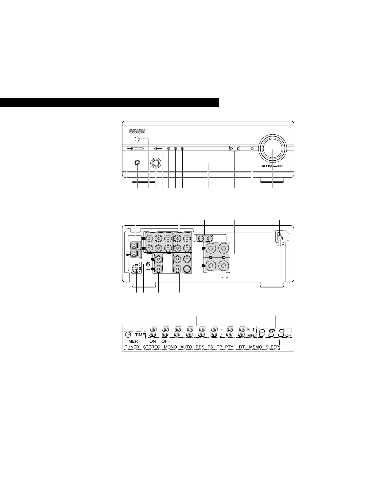
(1) Front Panel
q
Power operation switch (ON/STANDBY)
•(This turns the power for the entire system on and
off.)
•Press this once to turn the power on, then press
again to set the power to STANDBY mode.
•The LED color changes as follows, according to
the condition:
During power ON : green
During STANDBY : red
During TIMER STANDBY: orange
✻The muting mode is set when the main unit’s
power button is pressed and when the standby
mode is canceled from the remote control unit.
The power indicator flashes green when in the
muting mode, then stops flashing and turns green
once the set is in the operational mode.
✻If the indicator is flashing orange (quickly):
The protective circuit is activated.
If this happens, unplug the power cord to turn the
indicator off, then check the input and output
terminals on the rear panel. Check in particular for
short-circuiting of the speaker cords. Once all
connections have been corrected, plug the power
cord. (Wait for at least 10 seconds after turning
the power off before turning it back on.)
•When the DRA-201SA is connected in a system
with the 201SA series, its power button works as
the power button for the entire system. When
the DRA-201SA’s power turns on, the power of all
the connected system units also turns on.
✻Power is supplied to the DRA-201SA even when
the power is in the standby mode (low power
consumption).
wHeadphones jack (PHONES)
•Use this jack to listen to the sound over
commercially available headphones.
•When the headphones’plug is inserted into the
jack, the speaker output is automatically cut off,
so no sound is produced from the speakers.
e
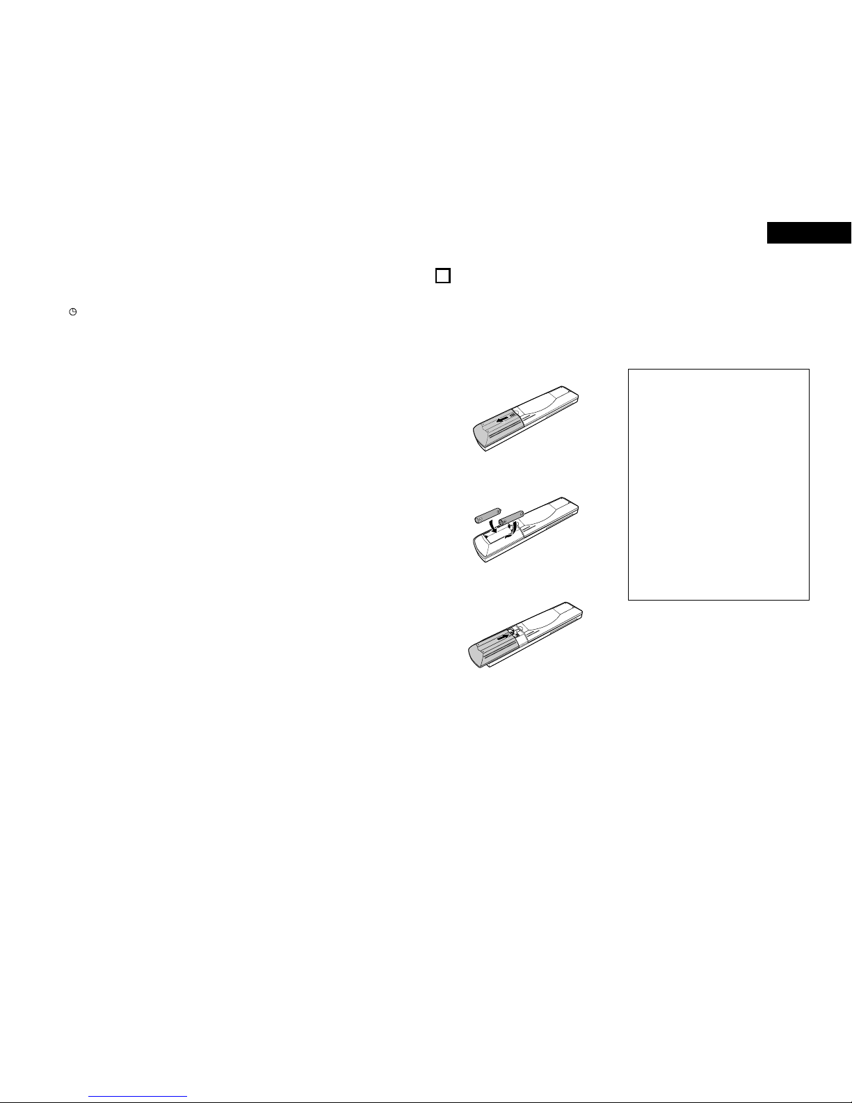
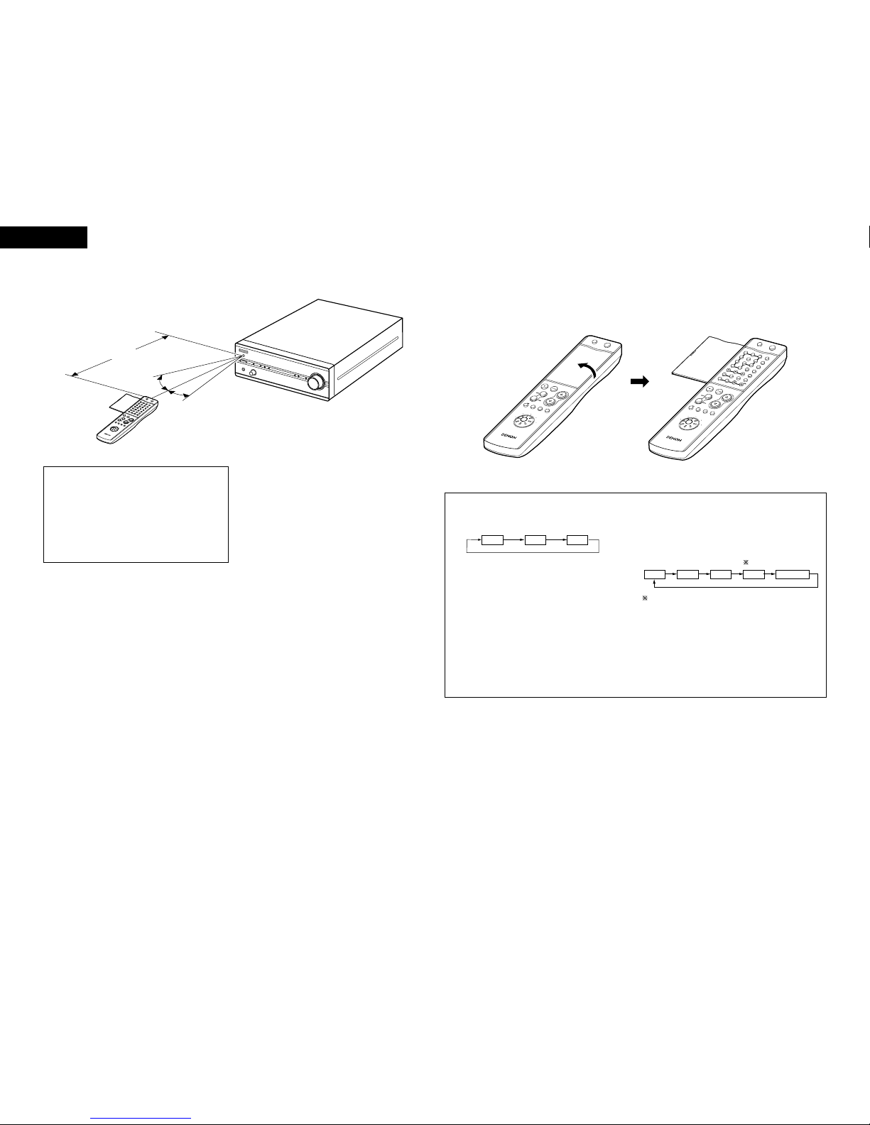
REMOTE SENSOR (Remote Control Sensor)
•Point the included remote control unit (RC-906) at
this sensor when operating it.
rFunction dial (FUNCTION)
•Switches the input function. Also used to set the
modes selected with the mode button.
(See pages 12, 13.)
tMode button (MODE)
•Use this to set the bass, treble and balance level.
(Refer to pages 12, 13.)
•Use this to set the loudness function to on or off.
(Refer to page 13.)
•Use this to set the speaker system. (Refer to
page 13.)
yTimer button (TIMER)
•Press this button during power ON mode to
confirm or change the display. Each time this
button is pressed, the display changes as follows:
Clock: Indicates the current time.
Timer Standby: Indicates the timer standby mode.
Use the PRESET/TUNING buttons to set the timer
standby mode on or off (refer to page 17).
•Press this buttons for at least 3 seconds to set the
timer (refer to page 16) or to confirm the timer
contents (refer to page 17).
Each time the PRESET/TUNING button is pressed,
the display changes as follows:
Frequency Clock Timer Standby
TIME EVERYDAY ONCE
TIME: Use this to set the time.
EVERYDAY: Use this to set the everyday timer.
ONCE: Use this to set the once timer.
•Press this button during in STANDBY mode to
switch ON/OFF (“Saving Energy Mode”) the clock
display.
uBand/RDS button (BAND/RDS)
•Each time this button is pressed, the band and FM
reception mode change as follows.
RDS PTY TP
FM AUTO FM MONO AM
•When the FM band, press this button for at least
3 seconds to select RDS search modes.
Each time this button is pressed, the display
changes as follows:
iMemory/set button (MEMORY/SET)
•Use this as the memory button when presetting
AM and FM stations.
•Use this as the set button when setting the time
and timer and when inputting data.
•When the PTY search mode, press this button to
select the type of program.
•Press this button for at least 3 seconds to change
the function of the PRESET/TUNING buttons
(Preset mode or Tuning mode).
oDisplay
Refer to page 9.
!0 Preset/Tuning buttons
(PRESET/TUNING UP AND DOWN)
•Use these buttons to call out the preset stations.
(PRESET UP DOWN) (See page 14.)
•Use these buttons to tune in AM and FM stations.
(TUNING UP/DOWN) (See page 13.)
!1 Source direct button (SOURCE DIRECT)
•When pressed and set to the “ON”position, the
signals bypass the tone control (bass, treble,
balance and loudness) circuits and are input
directly to the volume circuit, resulting in higher
quality sound.
•When pressed again and set to the “OFF”
position, the signals pass through the tone control
circuits, so the tone (bass, treble, balance and
loudness) can be adjusted as desired.
!2 Volume control dial (VOLUME)
•Use this to adjust the overall volume. (Rotary
Encoder System).
•The volume increases when the control is turned
clockwise (,), decreases when it is turned
counterclockwise (.).
•The volume increases and decreases in 70 steps
from the minimum (VOLUME 0) to the maximum
(VOLUME MAX).
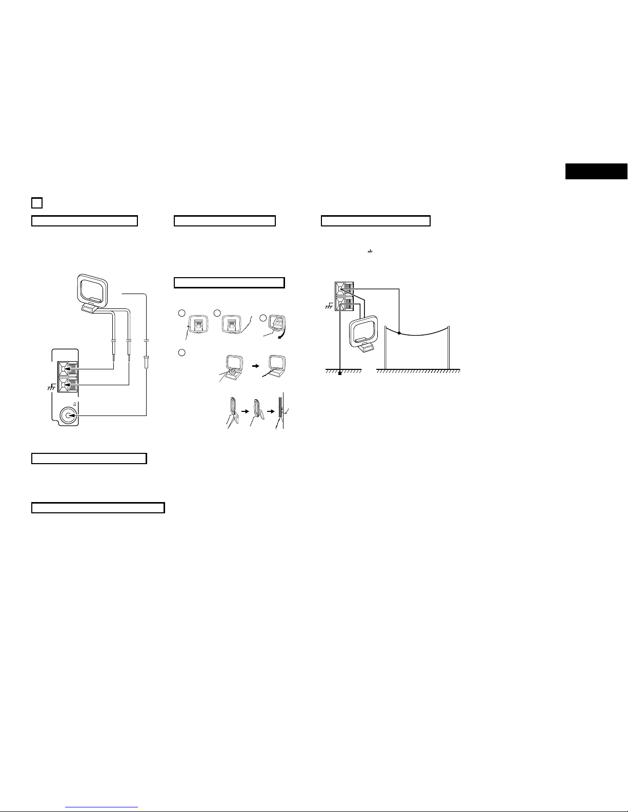
!3 FM antenna terminal
(ANTENNA TERMINAL FM)
•Connect the FM antenna here.
!4 SIGNAL GND (ground) terminal
•Connect the turntable’s ground wire here.
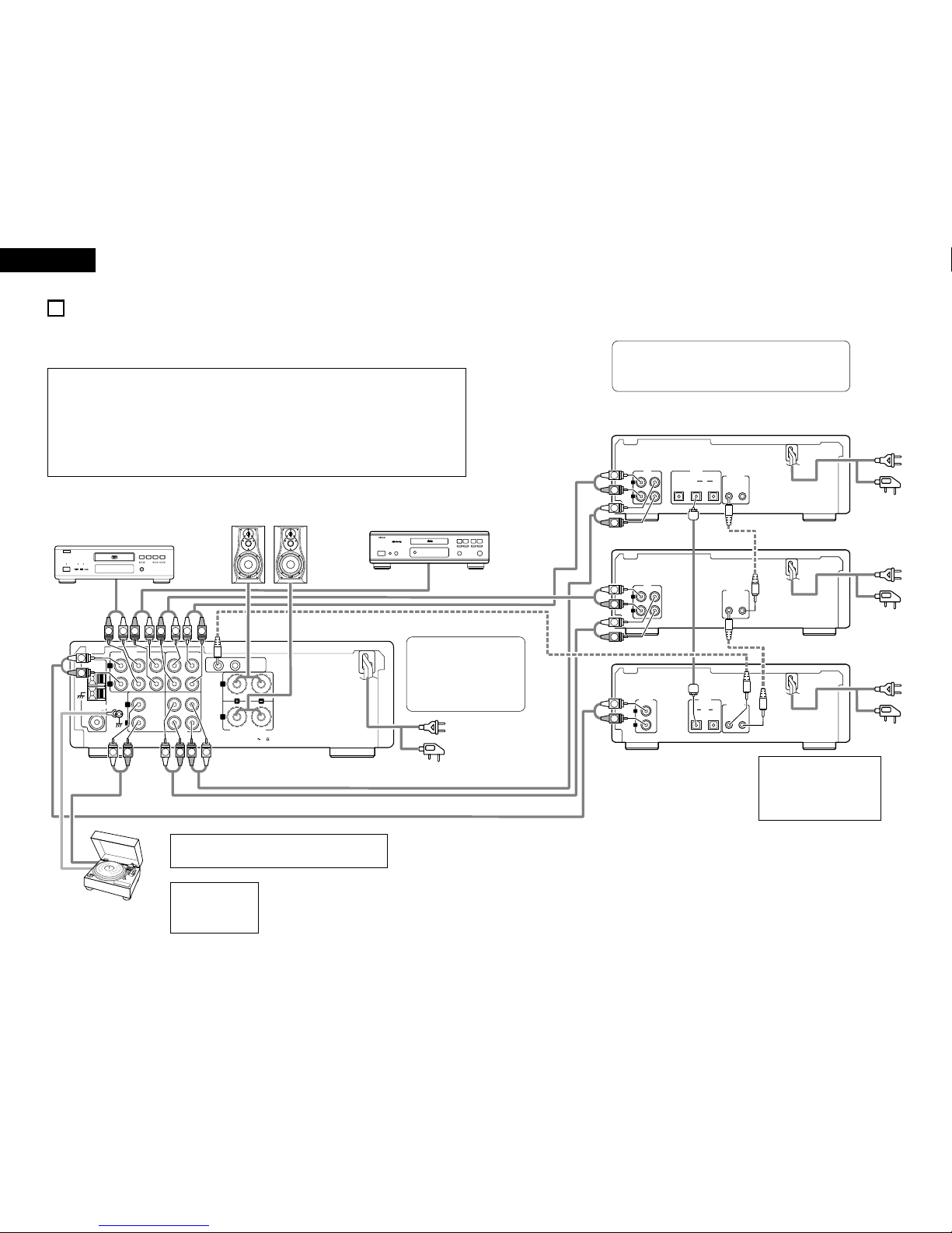
!5 INPUT terminals (INPUTS)
These are input terminals for CD player, turntable,
DVD or other playback components.
•AUX-2:
Use these to connect a video deck or other
component.
!6 TAPE and MD REC terminals (REC)
•Recording terminals (REC)
•These are output jacks for recording.
•TAPE:
Use these to connect a cassette deck.
•MD:
Use these to connect an MD recorder
!7 Power cord
•Plug this cord into a wall power outlet.
!8 Speaker terminals
(SPEAKER SYSTEM)
•Use these to connect the speakers.
!9 System connectors
(SYSTEM CONNECTOR 1 and 2)
•When connecting the 201SA series in a system,
connect these connectors to system connectors
on other system components.
(Use the system cords included with the other
components.)
@0 TAPE and MD PLAY terminals (PB)
•Playback terminals (PB)
@1 AM antenna terminal
(ANTENNA TERMINAL AM)
•Connect the AM antenna here.
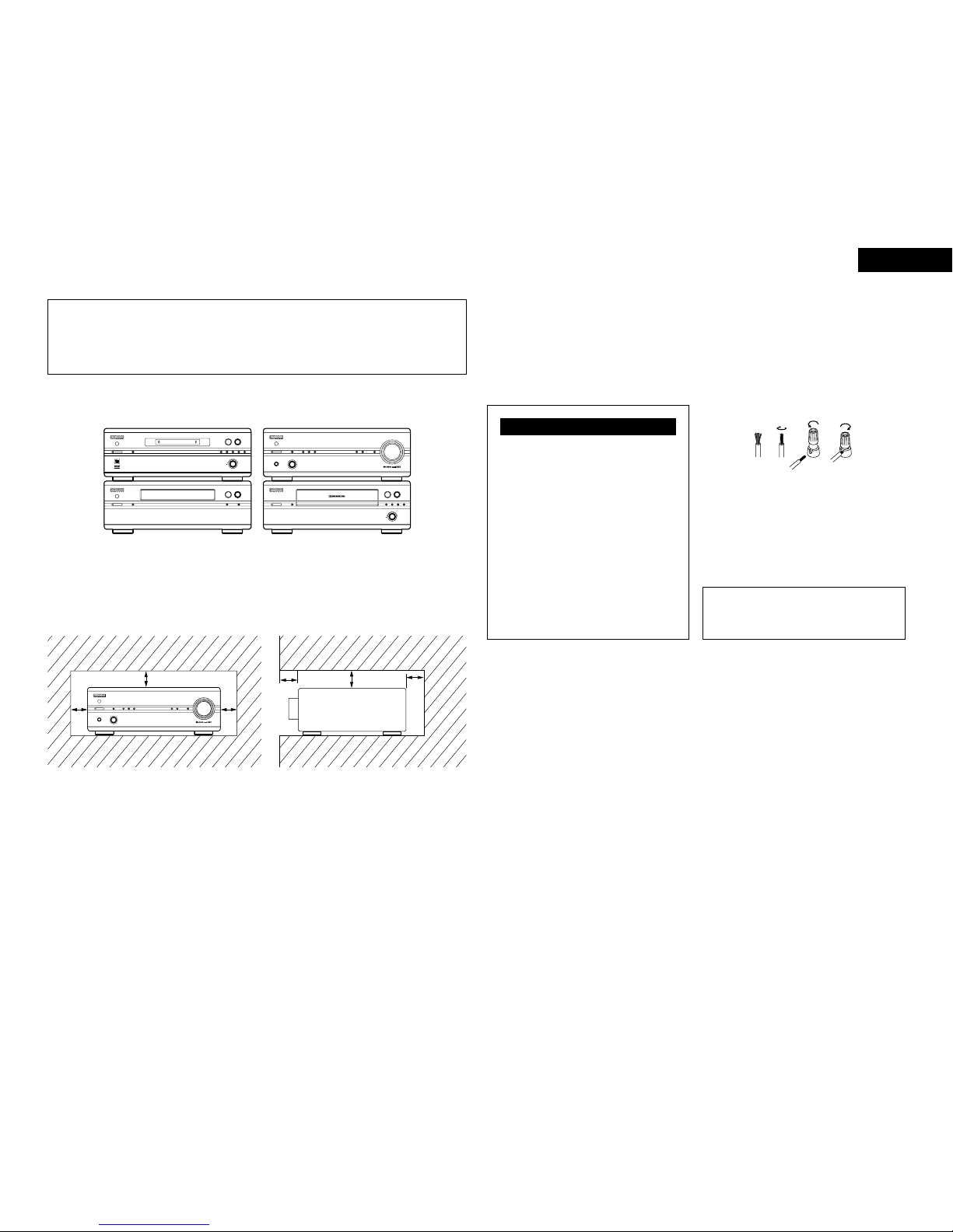
(2) Rear Panel
NOTE:
•This terminal is designed to reduce noise
when a turntable is connected.
This is not a safety ground.