manuals.online logo
Brands
  1. Home
  2. •
  3. Brands
  4. •
  5. Denon
  6. •
  7. Stereo Receiver
  8. •
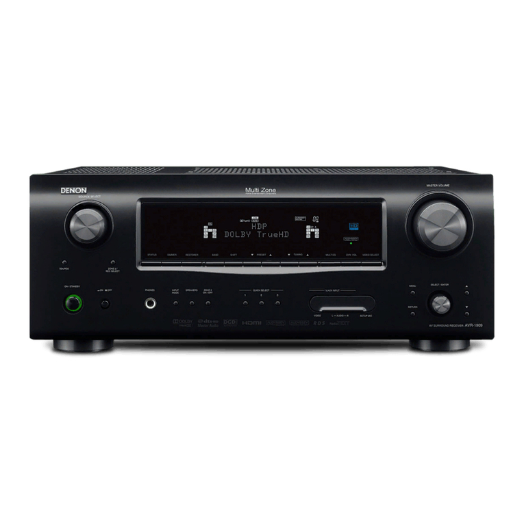
  9. Denon AVR-1712 User manual

Denon AVR-1712 User manual

Other manuals for AVR-1712

7

Other Denon Stereo Receiver manuals

Denon AVR-S950H Series User manual

Denon

Denon AVR-S950H Series User manual

Denon AVR 1709 - AV Receiver User manual

Denon

Denon AVR 1709 - AV Receiver User manual

Denon AVR-1712 User guide

Denon

Denon AVR-1712 User guide

Denon AVR-X8500HA User manual

Denon

Denon AVR-X8500HA User manual

Denon AVR-1604 User manual

Denon

Denon AVR-1604 User manual

Denon AVR-2311CI User manual

Denon

Denon AVR-2311CI User manual

Denon AVR-2801 User manual

Denon

Denon AVR-2801 User manual

Denon AVR-982 User manual

Denon

Denon AVR-982 User manual

Denon AVR-900 User manual

Denon

Denon AVR-900 User manual

Denon AVRX1500HOM User manual

Denon

Denon AVRX1500HOM User manual

Denon AVR-786 User manual

Denon

Denon AVR-786 User manual

Denon AVR-884 User manual

Denon

Denon AVR-884 User manual

Denon DRA-565RD User manual

Denon

Denon DRA-565RD User manual

Denon AVR-1612 User manual

Denon

Denon AVR-1612 User manual

Denon AVR-X4100W User manual

Denon

Denon AVR-X4100W User manual

Denon AVR-X1800H User manual

Denon

Denon AVR-X1800H User manual

Denon In-Command AVR-2313CI User manual

Denon

Denon In-Command AVR-2313CI User manual

Denon AVR-X4500H User manual

Denon

Denon AVR-X4500H User manual

Denon AVR-2802 User manual

Denon

Denon AVR-2802 User manual

Denon AVR-X250BT User manual

Denon

Denon AVR-X250BT User manual

Denon AVR-3805 User manual

Denon

Denon AVR-3805 User manual

Denon AVR-1906 User manual

Denon

Denon AVR-1906 User manual

Denon AVR-S750H User manual

Denon

Denon AVR-S750H User manual

Denon DRA-565RD User manual

Denon

Denon DRA-565RD User manual

Popular Stereo Receiver manuals by other brands

Teac AG-680 Service manual

Teac

Teac AG-680 Service manual

Kenwood KR-V888D instruction manual

Kenwood

Kenwood KR-V888D instruction manual

Teac AGV1050 owner's manual

Teac

Teac AGV1050 owner's manual

Sony STR-435 operating instructions

Sony

Sony STR-435 operating instructions

Pioneer Elite SC-68 Service manual

Pioneer

Pioneer Elite SC-68 Service manual

Pioneer SX-1250 operating instructions

Pioneer

Pioneer SX-1250 operating instructions

Marantz CINEMA 70S owner's manual

Marantz

Marantz CINEMA 70S owner's manual

Kenwood KMDX92 instruction manual

Kenwood

Kenwood KMDX92 instruction manual

Yamaha RX-830 owner's manual

Yamaha

Yamaha RX-830 owner's manual

Pioneer AVH-Z7250BT owner's manual

Pioneer

Pioneer AVH-Z7250BT owner's manual

Sony XAV-1500 operating instructions

Sony

Sony XAV-1500 operating instructions

Radio Shack DX-399 owner's manual

Radio Shack

Radio Shack DX-399 owner's manual

Sony STR-DE535 - Fm Stereo/fm-am Receiver operating instructions

Sony

Sony STR-DE535 - Fm Stereo/fm-am Receiver operating instructions

Pioneer SX-1000TA operating instructions

Pioneer

Pioneer SX-1000TA operating instructions

Yamaha MusicCast TSR-5B3D owner's manual

Yamaha

Yamaha MusicCast TSR-5B3D owner's manual

Sony STR-DG500 - Multi Channel Av Receiver Service manual

Sony

Sony STR-DG500 - Multi Channel Av Receiver Service manual

Sherwood Newcastle RX-770 operating instructions

Sherwood

Sherwood Newcastle RX-770 operating instructions

Panasonic AJSD955B - DVCPRO50 STUDIO DECK Brochure & specs

Panasonic

Panasonic AJSD955B - DVCPRO50 STUDIO DECK Brochure & specs

manuals.online logo
manuals.online logoBrands
  • About & Mission
  • Contact us
  • Privacy Policy
  • Terms and Conditions

Copyright 2025 Manuals.Online. All Rights Reserved.

D&M Holdings Inc.
SERVICE MANUAL
e
e
S0345-0V02DM/DG1109
• Some illustrations using in this service manual are slightly different from the actual set.
• Please use this service manual with referring to the operating instructions without fail.
• For purposes of improvement, specications and design are subject to change without notice.
Ver. 2
MODEL JP E3 E2 EK EA E1 E1K E1C
AVR-1712
P
AV SURROUND RECEIVER
Please refer to the
MODIFICATION NOTICE.
2
CONTENTS
SAFETY PRECAUTIONS..........................................................3
NOTE FOR SCHEMATIC DIAGRAM.........................................4
TECHNICAL SPECIFICATIONS................................................5
DIMENSION...............................................................................5
CAUTIONS IN SERVICING .......................................................6
Initializing AV SURROUND RECEIVER....................................6
Service Jig ................................................................................6
DISASSEMBLY..........................................................................7
1. FRONT PANEL ASSY ...........................................................9
2. PCB HDMI...........................................................................10
3. POWER TRANS MAIN........................................................11
4. PCB AUDIO_VIDEO ASSY .................................................11
5. PCB SMPS/PCB SPK.........................................................12
6. PCB REG/PCB REG_CNT..................................................13
7. RADIATOR ASSY................................................................14
SPECIAL MODE......................................................................16
Special mode setting button....................................................16
1. µcom/DSP Version display mode........................................17
2. Errors checking mode (Displaying the protection history)...19
3. Remote ID Setup mode.......................................................21
4. DIAGNOSTIC MODE
(Video/Audio (signal) path conrmation mode) ...................23
BLOCK DIAGRAM...................................................................25
JIG FOR SERVICING ..............................................................39
WHEN THE MICROPROCESSOR IS REPLACED WITH A
NEW ONE ................................................................................41
PROCEDURE FOR UPGRADING THE VERSION OF THE
FIRMWARE..............................................................................41
1. How to update by DFW .......................................................41
ADJUSTMENT.........................................................................45
SURROUND MODES AND PARAMETERS............................46
TROUBLE SHOOTING............................................................50
1. POWER...............................................................................50
2. Analog video........................................................................51
3. HDMI/DVI............................................................................56
4. AUDIO.................................................................................61
5. SMPS..................................................................................64
CLOCK FLOW & WAVE FORM IN DIGITAL BLOCK.............68
LEVEL DIAGRAM....................................................................69
PRINTED WIRING BOARDS...................................................75
7CH AMP ................................................................................75
SPMS .....................................................................................76
SPK ........................................................................................77
REG .......................................................................................79
FRONT_CNT ..........................................................................79
SIDE_CNT ..............................................................................80
REG_CNT ..............................................................................80
FRONT ...................................................................................81
FUNCTION..............................................................................82
FUNCTION CNT .....................................................................82
V.AUX .....................................................................................82
H/P .........................................................................................82
AUDIO_VIDEO ......................................................................83
HDMI ......................................................................................84
SCHEMATIC DIAGRAMS........................................................86
7CH-AMP UNIT (1/2) ..............................................................86
7CH-AMP UNIT (2/2) ..............................................................87
SPK UNIT................................................................................88
SMPS UNIT.............................................................................89
REG UNIT ...............................................................................90
SIDE_CNT UNIT .....................................................................91
FRONT_CNT UNIT .................................................................92
SIRIUS UNIT (AVR-2112CI ONLY) .........................................93
RS232C UNIT (AVR-2112CI ONLY)........................................93
AUDIO_VIDEO UNIT (1/3)......................................................94
AUDIO_VIDEO UNIT (2/3)......................................................95
AUDIO_VIDEO UNIT (3/3)......................................................96
HDMI UNIT (1/13) ...................................................................97
HDMI UNIT (2/13) ...................................................................98
HDMI UNIT (3/13) ...................................................................99
HDMI UNIT (4/13) .................................................................100
HDMI UNIT (5/13) .................................................................101
HDMI UNIT (6/13) .................................................................102
HDMI UNIT (7/13) .................................................................103
HDMI UNIT (8/13) .................................................................104
HDMI UNIT (9/13) .................................................................105
HDMI UNIT (10/13) ...............................................................106
HDMI UNIT (11/13)................................................................107
HDMI UNIT (12/13) ...............................................................108
HDMI UNIT (13/13) ...............................................................109
FRONT UNIT.........................................................................110
V.AUX UNIT ..........................................................................110
FUNCTION_CNT UNIT.........................................................110
FUNCTION UNIT ..................................................................110
H/P UNIT...............................................................................110
WIRING DIAGRAM................................................................111
EXPLODED VIEW..................................................................112
PARTS LIST OF EXPLODED VIEW......................................113
PACKING VIEW.....................................................................115
PARTS LIST OF PACKING & ACCESSORIES.....................115
SEMICONDUCTORS.............................................................117
1. IC's ....................................................................................117
2. FL DISPLAY.......................................................................142
PARTS LIST OF P.C.B. UNIT ................................................144
PCB 7CH_AMP ASS'Y..........................................................144
PCB SPK ASS'Y....................................................................148
PCB REG_CNT ASS'Y..........................................................151
PCB FRONT ASS'Y...............................................................153
PCB AUDIO_VIDEO ASS'Y ..................................................155
PCB HDMI ASS'Y..................................................................157
3
SAFETY PRECAUTIONS
The following items should be checked for continued protection of the customer and the service technician.
LEAKAGE CURRENT CHECK
Before returning the set to the customer, be sure to carry out either (1) a leakage current check or (2) a line to chassis
resistance check. If the leakage current exceeds 0.5 milliamps, or if the resistance from chassis to either side of the
power cord is less than 460 kohms, the set is defective.
Be sure to test for leakage current with the AC plug in both polarities, in addition, when the set's power is in each state (on,
off and standby mode), if applicable.
CAUTION Please heed the following cautions and instructions during servicing and
inspection.
◎Heed the cautions!
Cautions which are delicate in particular for servicing
are labeled on the cabinets, the parts and the chassis,
etc. Be sure to heed these cautions and the cautions
described in the handling instructions.
◎Cautions concerning electric shock!
(1) An AC voltage is impressed on this set, so if
you touch internal metal parts when the set is
energized, you may get an electric shock. Avoid
getting an electric shock, by using an isolating
transformer and wearing gloves when servicing
while the set is energized, or by unplugging the
power cord when replacing parts, for example.
(2) There are high voltage parts inside. Handle with
extra care when the set is energized.
◎Caution concerning disassembly and
assembly!
Through great care is taken when parts were
manufactured from sheet metal, there may be burrs
on the edges of parts. The burrs could cause injury if
ngers are moved across them in some rare cases.
Wear gloves to protect your hands.
◎Use only designated parts!
The set's parts have specic safety properties (re
resistance, voltage resistance, etc.). Be sure to use
parts which have the same properties for replacement.
The burrs have the same properties. In particular, for
the important safety parts that are indicated by the z
mark on schematic diagrams and parts lists, be sure to
use the designated parts.
◎Be sure to mount parts and arrange the wires
as they were originally placed!
For safety seasons, some parts use tapes, tubes or
other insulating materials, and some parts are mounted
away from the surface of printed circuit boards.
Care is also taken with the positions of the wires by
arranging them and using clamps to keep them away
from heating and high voltage parts, so be sure to set
everything back as it was originally placed.
◎Make a safety check after servicing!
Check that all screws, parts and wires removed or
disconnected when servicing have been put back in
their original positions, check that no serviced parts
have deteriorate the area around. Then make an
insulation check on the external metal connectors and
between the blades of the power plug, and otherwise
check that safety is ensured.
(Insulation check procedure)
Unplug the power cord from the power outlet,
disconnect the antenna, plugs, etc., and on the power.
Using a 500V insulation resistance tester, check that
the insulation resistance value between the inplug and
the externally exposed metal parts (antenna terminal,
headphones terminal, input terminal, etc.) is 1MΩ or
greater. If it is less, the set must be inspected and
repaired.
Many of the electric and the structural parts used in
the set have special safety properties. In most cases
these properties are difcult to distinguish by sight, and
the use of replacement parts with higher ratings (rated
power and withstand voltage) does not necessarily
guarantee that safety performance will be preserved.
Parts with safety properties are indicated as shown
below on the wiring diagrams and the parts list in this
service manual. Be sure to replace them with the parts
which have the designated part number.
(1) Schematic diagrams.......Indicated by the z mark.
(2) Parts lists.......Indicated by the zmark.
The use of parts other than the
designated parts could cause electric
shocks, res or other dangerous
situations.
CAUTION Concerning important safety
parts
4
NOTE FOR SCHEMATIC DIAGRAM
WARNING:
Parts indicated by the zmark have critical characteristics. Use ONLY replacement parts recommended by the manufacturer.
CAUTION:
Before returning the set to the customer, be sure to carry out either (1) a leakage current check or (2) a line to chassis resistance check. If
the leakage current exceeds 0.5 milliamps, or if the resistance from chassis to either side of the power cord is less than 460 kohms, the set
is defective.
WARNING:
DO NOT return the set to the customer unless the problem is identied and remedied.
NOTICE:
ALL RESISTANCE VALUES IN OHM. k=1,000 OHM / M=1,000,000 OHM
ALL CAPACITANCE VALUES ARE EXPRESSED IN MICRO FARAD, UNLESS OTHERWISE INDICATED. P INDICATES MICRO-MICRO
FARAD. EACH VOLTAGE AND CURRENT ARE MEASURED AT NO SIGNAL INPUT CONDITION. CIRCUITAND PARTS ARE SUBJECT
TO CHANGE WITHOUT PRIOR NOTICE.
NOTE FOR PARTS LIST
Parts indicated by "nsp" on this table cannot be supplied.
When ordering a part, make a clear distinction between "1" and "I" (i) to avoid mis-supplying.
A part ordered without specifying its part number can not be supplied.
General-purpose Carbon Chip Resistors are not included are not included in the P.W.Board parts list.
(Refer to the Schematic Diagram for those parts.)
Parts indicated by the zmark have critical characteristics. Use ONLY replacement parts recommended by the manufacturer.
General-purpose Carbon Film Resistor in the P.W.Board parts list. (Refer to the Schematic Diagram for those parts.)
Part indicated by "★" mark is not illustrated in the exploded view.
WARNING:
1.
2.
3.
4.
5.
6.
●Resistors
RD: Carbon
RC: Composition
RS : Metal oxide film
RW: winding
RN: Metal film
RK : Metal mixture
P : Pulse-resistant type
NL : Low noise type
NB : Non-burning type
FR : Fuse-resistor
F : Lead wire forming
2B : 1/8 W
2E : 1/4 W
2H : 1/2 W
3A : 1 W
3D : 2 W
3F : 3 W
3H : 5 W
F : ±1%
G:±2%
J : ±5%
K : ±10%
M : ±20%
Ex.: RN
Type 14K
Shape
and per-
formance
2E
Power 182
Resist-
ance
G
Allowable
error
FR
Others
*Resistance 1800ohm=1.8kohm1 8 2 Indicates number of zeros after effective number.
2-digit effective number.
1.2ohm1 R 2
2-digit effective number, decimal point indicated by R.
1-digit effective number.
: Units: ohm
●Capacitors
CE : Aluminum foil
electrolytic
CA : Aluminium solid
electrolytic
CS : Tantalum electrolytic
CQ: Film
CK : Ceramic
CC: Ceramic
CP : Oil
CM: Mica
CF : Metallized
CH: Metallized
HS : High stability type
BP : Non-polar type
HR: Ripple-resistant type
DL : For change and discharge
HF : For assuring high frequency
U : UL part
C : CSA part
W : UL-CSA part
F : Lead wire forming
0J : 6.3 V
1A : 10 V
1C : 16 V
1E : 25 V
1V : 35 V
1H : 50 V
2A : 100 V
2B : 125 V
2C : 160 V
2D : 200 V
2E : 250 V
2H : 500 V
2J : 630 V
F : ±1%
G:±2%
J : ±5%
K : ±10%
M : ±20%
Z : ±80%
: - 20%
P : +100%
C : ±0.25pF
D : ±0.5pF
= : Others
Ex.: CE
Type 04W
Shape
and per-
formance
1H
Dielectric
strength
3R2
Capacity M
Allowable
error
BP
Others
・Units:μF.
2200μF2 2 2 Indicates number of zeros after effective number.
2-digit effective number. ・Units:μF.
2.2μF2 R 2
2-digit effective number, decimal point indicated by R
1-digit effective number.
*Capacity (electrolyte only)
・When the dielectric strength is indicated in AC,"AC" is included after the dielectric strength value.
*Capacity (except electrolyte)
・Units:pF
2200pF=0.0022μF2 2 2
Indicates number of zeros after effective number. (More than 2)
2-digit effective number. ・Units:pF
220pF2 2 1
2-digit effective number.
Indicates number of zeros after effective number. (0 or 1)
NOTE FOR PARTS LIST
5
TECHNICAL SPECIFICATIONS
nAudio Section
• Poweramplier
Rated output :
Front :
90 W + 90 W (8 Ω, 20 Hz – 20 kHz with 0.08 % T.H.D.)
125 W + 125 W (6 Ω, 1 kHz with 0.7 % T.H.D.)
Center :
90 W (8 Ω, 20 Hz – 20 kHz with 0.08 % T.H.D.)
125 W (6 Ω, 1 kHz with 0.7 % T.H.D.)
Surround :
90 W + 90 W (8 Ω, 20 Hz – 20 kHz with 0.08 % T.H.D.)
125 W + 125 W (6 Ω, 1 kHz with 0.7 % T.H.D.)
Surround back:
90 W + 90 W (8 Ω, 20 Hz – 20 kHz with 0.08 % T.H.D.)
125 W + 125 W (6 Ω, 1 kHz with 0.7 % T.H.D.)
Output connectors : 6 – 16 Ω
• Analog
Input sensitivity/Input impedance : 200 mV/47 kΩ
Frequency response: 10 Hz – 100 kHz — +1, –3 dB (DIRECT mode)
S/N : 100 dB (IHF–A weighted, DIRECT mode)
nVideo section
• Standard video connectors
Input/output level and impedance : 1 Vp-p, 75 Ω
Frequency response : 5 Hz – 10 MHz — 0, –3 dB
• Color component video connector
Input/output level and impedance :
Y (brightness) signal — 1 Vp-p, 75 Ω
PB/ CB signal — 0.7 Vp-p, 75 Ω
PR/ CR signal — 0.7 Vp-p, 75 Ω
Frequency response : 5 Hz – 60 MHz — 0, –3 dB
nTuner section
[FM](Note: μV at 75 Ω, 0 dBf = 1 x 10–15 W)
Receiving Range :
[FM] 87.5 MHz – 107.9 MHz [AM]520 kHz – 1710 kHz
Usable Sensitivity :
[FM]1.2 μV (12.8 dBf) [AM]18 μV
50 dB Quieting Sensitivity :
[FM]MONO 2.8 μV (20.2 dBf)
S/N (IHF-A) :
[FM]MONO 70 dB (IHF–A weighted, DIRECT mode)
STEREO 67 dB (IHF–A weighted, DIRECT mode)
Total harmonic Distortion (at 1 kHz) :
[FM]MONO 0.7 %
STEREO 1.0 %
nGeneral
Power supply : AC 120 V, 60 Hz
Power consumption :
460 W
0.1 W (Standby)
3 W (CEC standby)
Maximum external dimensions :
435 (W) x 162 (H) x 382 (D) mm
Weight : 10.2 kg
nRemote Control Unit (RC-1156)
Batteries : R6/AA Type (two batteries)
Maximum external dimensions : 53 (W) x 224 (H) x 28 (D) mm
Weight : 160 g (including batteries)
DIMENSION
245.043.5
30.5 30.586.0
435.0
344.0
162.0
22.0
53.8 213.9
338.5
382.0
16.0
146.0
21.5
6
CAUTIONS IN SERVICING
Initializing AV SURROUND RECEIVER
AV SURROUND RECEIVER initialization should be performed when the μcom, peripheral parts of μcom, and Digital
P.W.B. were replaced.
1. Turn off the power pressing ON/STANDBY button.
2. Press ON/STANDBY button while simultaneously while pressing DOCK CONTROL 8 and DOCK CONTROL 9
buttons.
3. Check that the entire display is ashing at intervals of about 1 second, and then release the 2 buttons.
The microprocessor will be initialized.
Service Jig
When you repair the printing board, you can use the following JIG (Extension cable kit).
Please order it from DENON Ofcial Service Distributor in your region if necessary.
8U-110084S : EXTENSION UNIT KIT : 1 Set
(Refer to 39 page.)
When you update the rmware by DFW, you can use the following JIG (RS232C to internal connector conversion adapter
with 4P FFC cable kit ).
Please order to DENON Ofcial Service Distributor in your region if necessary.
8U-210100S : WRITING KIT : 1 Set
(Refer to 41 page.)
Note: • If step 3 fails, start over from step 1.
• All user settings will be lost and the factory setting will be recovered after the set is initialized.
So make sure to note down your setting beforehand for restoring after the initialization.
ON/STANDBY DOCK CONTROL 8
DOCK CONTROL 9
7
DISASSEMBLY
• Disassemble in order of the arrow in the following gure.
• In the case of the re-assembling, assemble it in order of the reverse of the following ow.
• In the case of the re-assembling, observe "attention of assembling".
• If wire bundles are untied or moved to perform adjustment or replace parts etc., be sure to rearrange them neatly as
they were originally bundled or placed afterward.
Otherwise, incorrect arrangement can be a cause of noise generation.
FRONT PANEL ASSY
Refer to "DISASSEMBLY
1. FRONT PANEL ASSY"
and "EXPLODED VIEW"
PCB H/P
(Ref. No. of EXPLODED VIEW : P1)
PCB FUNCTION
(Ref. No. of EXPLODED VIEW : P2)
PCB FUNCTION_CNT
(Ref. No. of EXPLODED VIEW : P3)
PCB FRONT
(Ref. No. of EXPLODED VIEW : P4)
PCB V.AUX
(Ref. No. of EXPLODED VIEW : P5)
RADIATOR ASSY
Refer to "DISASSEMBLY
7. RADIATOR ASSY"
and "EXPLODED VIEW"
PCB 7CH-AMP ASSY
(Ref. No. of EXPLODED VIEW : P8)
PCB GUIDE_TOP
(Ref. No. of EXPLODED VIEW : P9)
PCB GUIDE_L
(Ref. No. of EXPLODED VIEW : P10)
POWER TRANS MAIN
Refer to "DISASSEMBLY
3. POWER TRANS MAIN"
and "EXPLODED VIEW"
POWER TRANS MAIN
(Ref. No. of EXPLODED VIEW : 31)
TOP COVER
PCB HDMI
Refer to "DISASSEMBLY
2. PCB HDMI"
and "EXPLODED VIEW"
PCB HDMI ASSY
(Ref. No. of EXPLODED VIEW : P16
PCB SMPS/PCB SPK
Refer to "DISASSEMBLY
5. PCB SMPS/PCB SPK"
and "EXPLODED VIEW"
PCB SMPS
(Ref. No. of EXPLODED VIEW : P18)
PCB SPK
(Ref. No. of EXPLODED VIEW : P19)
PCB REG/PCB REG_CNT
Refer to "DISASSEMBLY
6. PCB REG/PCB REG_CNT"
and "EXPLODED VIEW"
PCB REG
(Ref. No. of EXPLODED VIEW : P11)
PCB REG_CNT
(Ref. No. of EXPLODED VIEW : P12)
PCB AUDIO_VIDEO ASSY s
Refer to "DISASSEMBLY
4. PCB AUDIO_VIDEO ASSY"
and "EXPLODED VIEW"
PCB AUDIO_VIDEO ASSY
(Ref. No. of EXPLODED VIEW : P13)
PCB SIDE_CNT
(Ref. No. of EXPLODED VIEW : P14)
PCB FRONT_CNT
(Ref. No. of EXPLODED VIEW : P20)
8
About the photos used for "descriptions of the DISASSEMBLY" section
• The shooting direction of each photograph used herein is indicated on the left side of the respective photograph as
"Shooting direction: ***".
• Refer to the diagram below about the shooting direction of each photograph.
• Photographs with no shooting direction indicated were taken from the top of the set.
The viewpoint of each photograph
(Shooting direction)
[View from the top]
Front side
Shooting direction: B
Shooting direction: DShooting direction: C
Shooting direction: A
9
1. FRONT PANEL ASSY
(1) Remove the screws.
(2) Disconnect the connector wires and FFC cable, then remove the screws.
TOP COVER FRONT PANEL ASSY
→
Proceeding :
View from the bottom
CP101
FFC cable
STYLE PIN : Loosen
STYLE PIN : Loosen
Please refer to "EXPLODED VIEW" for the disassembly method of each P.W.B included in FRONT PANEL ASSY.
10
2. PCB HDMI
(1) Remove the screws.
(2) Disconnect the connector wires and FFC cable, then remove the HOLDER. Disconnect the connector board.
TOP COVER PCB HDMI
→
Proceeding :
Shooting of photograph: A
CX1
CN8
Board to board
Board to board
FFC cable
HOLDER