manuals.online logo
Brands
  1. Home
  2. •
  3. Brands
  4. •
  5. Denon
  6. •
  7. Stereo Receiver
  8. •
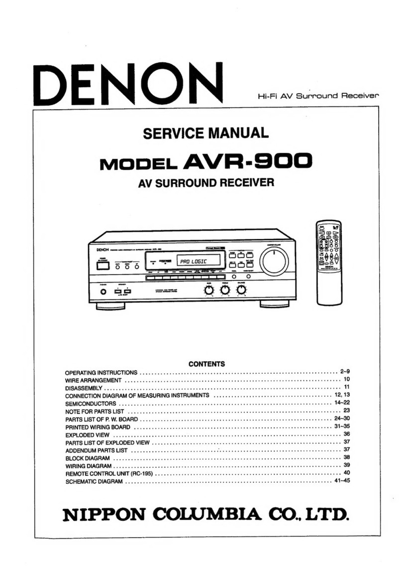
  9. Denon DRA-25 User manual

Denon DRA-25 User manual

D
F
N
O
N
Hi-Fi
AM-FM
Stereo
Receiver
MODEL
DRA=-25/25L
AM-FM
STEREO
RECEIVER
DRA-25L
CONTENTS
PRECAUTIONS
FOR
INSTALLATION
ADVICE
FOR
USE
SPECIFICATIONS
NAME
OF
EACH
PART
CONNECTION
ANTENNA
INSTALLATION
REMOVAL
OF
EACH
SECTION
METHOD
OF
ADJUSTMENTS
CONNECTION
DIAGRAM
OF
MEASURING
INSTRUMENTS
SEMICONDUCTORS
DRA25
BLOCK
DIAGRAM
PRINTED
WIRING
BOARD
PATTERNS
AND
PARTS
LIST
PRINTED
WIRING
BOARD
EXPLODED
VIEW
OF
CHASSIS
AND
CABINET
&
PARTS
LIST
EXPLODED
VIEW
OF
CHASSIS
AND
CABINET
WIRING
DIAGRAM
SCHEMATIC
DIAGRAM
NIPPON
COLUMBIA
Co.
LTD.
MDRA-25/25St
PRECAUTIONS
FOR
INSTALLATION
DRA-25/25L
uses
a
newly
developed
heat
emitting
unit
by
employing
heat
pipes.
Since
the
heat
pipes
contain
a
coolant,
the
DRA-25/25L
must
be
set
level
or
the
desired
heat
emitting
effect
cannot
be
achieved.
Always
instal!
this
unit
horizontally.
ADVICE
FOR
USE
e
Do
not
place
the
set
in
direct
sunlight,
in
hot
areas
such
as
near
heating
equipment,
with
high
humidity
or
dust
levels.
This
may
cause
damage
to
the
unit.
Check
that
all
parts
are
connected
correctly
before
turning
on
the
power
source.
When
user
is
absent
for
jong
periods,
be
sure
to
remove
plug
from
wall
socket.
Do
not
use
insecticide,
benzene
or
thinner
near
the
unit,
or
the
cabinet
color
will
fade.
Avoid
using
polish:
use
a
soft
cloth
(e.g.
silicon
cloth),
ciligy
vue
wry,
‘4
Z
It
is
not
recommended
to
place
players,
decks
and
other
objects
on
the
DRA-25
or
DRA-25L
so
that
the
vents
are
blocked,
This
will
cause
internal
temperature
rise
and
equipment
failure.
Do
not
use
the
DRA-25
or
DRA-25L
in
a
closed
cabinet
or
container.
This
will
cause
internal
temperature
rise
abnormally.
For
United
Kingdom
model
only.
WARNING:
As
the
colours
of
the
wires
in
the
mains
lead
of
this
appliance
may
not
correspond
with
the
coloured
markings
identifying
the
terminals
in
your
plug
proceed
as
follows:
The
wire
which
is
coloured
blue
must
be
connected
to
the
terminal
which
is
marked
with
the
letter
N
or
coloured
black.
The
wire
which
is
coloured
brown
must
be
connected
to
the
terminal
which
is
marked
with
the
fetter
L
or
coloured
red.
The
wire
which
is
coloured
BROWN
must
be
connected
to
the
terminal
which
is
marked
with
the
letter
L
or
coloured
RED.
IMPORTANT
The
wires
in
this
mains
lead
are
coloured
in
accord-
ance
with
the
following
code:
Blue:
Neutral
Brown:
Live
SPECIFICATIONS
AMPLIFIER
SECTION
Rated
Output
Power:
Power
Bandwidth
(IHF):
Total
Harmonic
Distortion
{20
Hz
to
20
kHz):
Frequency
Responses:
input
Sensithvity
and
Impedance:
Maximum
Input
Level
(at
1
kHz):
Signal
to
Noise
Ratio
{IHF-A):
Tone
Controls:
Loudness,
Control
Effect:
3OW
+
30W
per
channel
minimum
RAMS,
both
channels
driven
at
8
ohms
from
20
Hz
~
20
kHz
no
more
then
0.05%
total
harmonic
distortion
45W
+
45W
per
channel
minimum
RMS,
both
channels
driven
at
4ohms
from
1
kHz
DIN
no
more
than
1%
total
harmonic
distortion
10
Hz
~
40
kHz
(T.H.D.
0.1%
both
ch,
driven
at
8
ohms)
-3
dB
power
into
8
ohms
0.04%
PHONO
RIAA
Standard
Curve
(Recording
Output)
MM
20
Hz
~
20
kHz
+
0.5
dB
20
Hz
~
50
kHz
+
1.5
dB
PHONO
MM
2.5mV_
47k
ohms
AUX,
TAPE,
CD
150mV
33
k
ohms
PHONO
MM
150
mV
PHONO
MM
78
dB
at
5.0
mV
input
AUX,
TAPE,
CD
95
dB
at
150
mV
input
BASS
+10
dB
at
100
Hz
TREBLE
+10
dB
at
10
kHz
VARIABLE
LOUDNESS
10
posi-
tions,
50
Hz/10
kHz,
+10
dB/+5
dB
TUNER
SECTION
LEM)
(note:
#V
at
75
ohms,
0
dBf
=
1
x
40°!FW)
Recelving
Range:
87.5
~
108
MHz
Usable
Sensitivity:
0.9
pV
(10.3
dBF)
S/N
50
dB
Quieting
Sensitivity:
Signal
to
Noise
Ratio
(IHF-A):
Tota!
Harmonic
Distortion
{at
1
kHz):
Capture
Ratio:
image
Rejection:
AM
Suppression:
Selectivity
(+300
kHz):
Frequency
Response:
Stereo
Separation
(at
1
kHz):
(mw)
Recsiving
Range:
Usable
Sensitivity:
Signal
to
Noise
Ratio:
[LW]
(DRA-251
only)
Receiving
Range:
Usable
Sansitivity:
GENERAL
Power
Supply:
Power
Consumption:
Dimensions:
Weight:
a
es
DRA-25/25L
ma
MONO
=
1.6
#V
(15.3
dBf)
STEREO
23
pV
(38.5
dBf)
MONO
82¢B
STEREO
78
dB
MONO
0.2%
STEREO
0.4%
1.5
dB
70
dB
50
dB
60
dB
30
Hz
~
18
kHz
70-2
dB
40
dB
522
~
1611
kHz
18
pV
53
dB
153
~
360
kHz
30
pV
AC
220
V
50
Hz
{for
Europe)
AC
240
V
50
Hz
(for
U.K,
&
Australia)
120
W
434
mm
(17-3/32")
W
x
112mm
(4-13/32"")
H
x
278
mm
(10-15/16")
D
5.5
kg
(12
Ibs
2
0z)
Design
and
specifications
are
subject
to
change
without
prior
notice.
NOTE:
The
following
codes
correspond
to
the
appropriate
models.
E2
for
Europe,
EA
for
Australia
and
EK
for
U.K.
This
Service
Manual
is
prepared
based
on
E2
Black
Version.
mg
ORA-25/25L
eaaeeeeerereereeereeeeeeee
eee
rearrange
SE
tn}
DRA-25/25L
m
NAME
OF
EACH
PART
FRONT
PANEL
BACK
PANEL
DENON
mec
sso
comonnt
snse
srenec
mech
vee
T2140
We
at
SHEAAEE
SYSTEMS
e
le
fi}
TR
\
WARRING
Tp
eapace
Tee
sign
oF
rE
ot
cLecTAIG
ba
ft
Fo
SAN
Om
ANT
NSE
IWS
APA
LiaNCE
ml
Hl
Ay
=e
AN
stant
WANING
=
Seeca
MAZAND
08
wat
PER
pt
AVIS:
seat
ME
OAC
CLéCTIngUE
—
zy;
i
TB
BS
8%.
©
1B
ue
It
OID
sruato
emo
AIO
Mam
see
a)
a
per
es
|
|
{DRA-25)
DISPLAY
cwmwi
CI
Fmt
UJ
0
FRONT
PANEL
POWER
(Power
Switch)
PHONES
(Headphones
Jack)
SPEAKERS
(Speaker
Select
Switch)
(DRA-25
only)
BASS
(Bass
Control)
TREBLE
(Treble
Control)
VARIABLE
LOUDNESS
(Loudness
Control)
BALANCE
(Balance
Control)
INPUT
SELECTOR
(Sound
Input
Select
Knob)
TAPE
MONITOR
(TAPE
Monitor
Switch)
CD
DIRECT
(CD
Direct
Switch)
QOOOWOOSQOOO
DISPLAY
SIGNAL
(Signal
Strength
Indicator)
STEREO/MONO
(Stereo/Mono
Indicator)
TUNING
MODE
(AUTO/MANUAL)
SHIFT
(Shift
Indicator)
a
ee
@QQC@OOQOOO
QO®)
VOLUME
(Volume
Control)
TUNING
MODE
(Tuning
Mode
Button)
FM
MODE
(FM
Mode
Button)
BAND
SELECT
(Band
Selector
Button)
TUNING
(Tuning
Buttons)
SHIFT
(Shift
Button)
MEMORY
(Memory
Button)
PRESET
CHANNEL
1
~
16
(Station
Presetting
Buttons)
MEMORY
(Memory
Indicator)
CHANNEL
FREQUENCY
DISPLAY
(Frequency
Indicator)
(DRA-25)
or
{DRA-25L)
)
BACK
PANEL
FM
ANT
(FM
Antenna
Terminals)
AM
ANT
{AM
Antenna
Terminats)
GND
(Grounding
Terminal)
AM
LOOP
ANT
(AM
Loop
Antenna)
PHONO
(Phono
Input
Terminals)
QOQOOO
ce
hersraraes
ARMING
sance
nuzans
0
m42
DCR
AVIS:
miStEL
OC
COG
CLECTATENE
ms
Wot
WARMING
:
ro
acouet
rae
esa
af
fiat
on
CeCcTING
WO
AAT
ERPESE
TIS:
APPLLANCE
Ta
tain
ge
wacsTaRe,
srg
srs
=
+
COLO
CD/AUX
TAPE
(Audio
Playback
and
Recording
Terminals)
SPEAKER SYSTEMS
(Speaker
Terminals)
AC
CORD
(Power
Cord)
mDRA-25/25L
CONNECTION
(This
is
a
figure
of
the
DRA-25L)
SPEAKER
(RIGHT)
@o
®
@
TURN
TABLE
OnE
+
De:
AUDIO
PIN
CORD
SPEAKER
(LEFT)
TAPE
DECK
BG)
REC
G)
&
©
©
AOL
LINE
OUT
CD
PLAYER
or
OTHER
AUDIO
EQUIPMENT
SPEAKER
CONNECTION
Confirm
polarity
(+,
—)
and
left
and
right
channels
(L,
R).
Connect
the
speaker
pairs
to
the
SPEAKER
terminals
A
or
B
on
the
back
panel.
Connections
must
be
made
with
power
cord
disconnected.
<
1.
Peel
off
the
sheathing
from
”
the
end
of
the
cord.
|
aw
2.
Twist
the
wire
strands.
i?
3.
Loosen
the
speaker
terminal,
insert
the
wire
Jead
portion
of
the
code,
and
then
tighten
the
terminal.
>
@
i
|
ANTENNA
INSTALLATION
©
FM
ANTENNA
The
accessory
T-type
indoor
antenna
(300
ohms)
can
be
used
inside
wooden
houses
for
local
FM
stations
and
strong
signals.
Orient
the
T-shaped
part
for
optimum
reception
and
mount
the
antenna
on
the
wall
or
ceiling.
(FM
indoor
antennas
may
not
consistently
ensure
stable
reception,
due
to
environment
changes.
In
such
cases
use
an
FM
indoor
antenna
temporarily
until
an
outdoor
antenna
is
installed.)
75
ohms
coaxial
cable
(3C-2V,
5C-2V)
is
preferable
to
obtain
better
performance
of
the
tuner.
(To
use
of
a
300
ohms
FM
outdoor
antenna,
connect
to
the
300
ohms
terminals.)
AM
ANTENNA
Attach
the
accessory
AM
loop
antenna
to
the
antenna
holder
on
the
back
panel.
Connect
the
leads
to
AM
and
GND
terminal.
Use
this
terminal
also
for
an
outdoor
antenna.
Orient
the
loop
antenna
horizontally
to
obtain
optimum
reception.
Where
broadcast
stations
are
distant
and
only
weak
signals
are
received,
or
where
signals
are
blocked
by
obstacles,
instal!
an
AM
outdoor
antenna.
GROUNDING
If
there
is
reception
noise,
use
of
grounding
wire
is
recommended.
Connect
a
thick
insulated
wire
to
the
“GND”
terminal,
and
attach
the
unconnected
bare
end
to
a
metal
water
pipe,
grounding
rod,
or
grounded
copper
plate.
*
Never
connect
the
grounding
wire
to
a
gas
pipe.
This
could
cause
fire
or
explosion.
7Sohm
COAXIAL
CABLE
ES
>
ANTENNA
{
PUSH
ADAPTER
FM
OUTDOOR
ANTENNA
Put
the
core
wire
into
the
900
of
the
terminal
Note:
«@
Two
FM
antennas
should
not
be
connected
simultaneously.
©
Even
if
an
external
AM
antenna
is
used,
the
AM
loop
antenna
should
not
be
disconnected.
e@
AM
loop
antenna
lead
terminals
do
not
touch
the
metal
part
of
the
back
panel.
ORA-25/25L.
mt
sg
ORA-25/25t
REMOVAL
OF
EACH
SECTION
1.
Top
Cover
1)
Unfasten
the
7
screws,
2)
Detach
the
top
cover
by
means
of
lifting
it
up-
ward,
2.
Front
Panel
1)
Pull
out
the
knobs,
(Main
volume
control
knob
x
1;
input
selector
knob
x
1;
tone,
balance,
etc.
x
4.)
2}
Remove
the
4
screws
from
the
bottom.
3)
Push
downward
the
4
claws
on
the
top
of
inner
panel
to
release
catching
of
front
panel,
then
pull
the
front
panel
frontward
and
detach.
Fig.
4
Front
Panel
to
KA
inner
Panel
oe
ae
Push
the
4
claws
on
the
top
and
|
pull
the
front
panel
frontward,
Puil
out
the
knob,
&
3x10CBTS(P)x4
3.
PCB
1)
Remove
the
power
knob.
2)
Unfasten
the
4
screws.
(Inner
panel
x
2;
power
switch
x
2.)
3)
Remove
the
5
screws
on
the
back
panel.
4)
Remove
the
2
screws
securing
the
heat
pipe
fin.
5)
Detach
the
AC
cord
bushing.
6)
Remove
the
3
heads
of
PCB
holder
and
pull
the
holder
upward
to
detach.
Fig.
5
i
re
Back
Panet
PCB
Heat
Pipe
Fin
3x6CBTS(8).8
3x8CBTS(S)x2
Upper
side
of
Securing
Screw
x2
POWER
SWITCH.
t
P
Back
Panel
!
a
3x6CBTS(S)-Bx3
|
Detached
condition
3x8CBTS(S)x4
:
Remove
PCB
hoider.
"
{3
portions.)
Fig.
6
—~8-
a
a
a
I
TE
ES
CA
A-P
5/25.
me
4,
Inner
Panel
1)
Take
out
the
speed
nut
of
headphone
jack.
2)
Pull
out
the
speaker
selector
switch
knob
and
remove
the
1
screw
fixing
the
switch.
(For
EK
and
LE2
versions,
disregard
this
step.)
3}
Unfasten
the
1
screw
holding
the
tone
volume
controls.
4)
Remove
the
screw
tightening
the
input
selector.
5)
Remove
the
nut
and
washer
securing
the
main
volume
control.
6)
Pull
frontward
the
inner
pane!
to
detach.
No
connection
in
either
type
of
both
LKEK
and
LKE2,
5.
FLD,
Tact
Switch
PCBs
Remove
the
push-rivet
holding
the
to
remove
each
PCB.
respective
PCB
Speaker
Selector
IS
-
Switch
Speed
nut
of
headphone
jack
a
Pa
2
oa
<
N
N
“
~N
-
TONE
Vol,
Nut and
Washer
of
Main
Volume
Control.
3x8CBTS(S)x3
(DRA-25)
Input
3x8CBTS(S)x2
{DRA-25L)
Selector
Fig.
7
FLD
PCB
inner
Panel
TACT
SW
PCB
Fig.
8
wm
DRA-25/25:L
METHOD
OF
ADJUSTMENTS
SP
TERMINAL
TPt
TPS
E)
Gq
og
TPH
TPI2
La
IDLE
CURRENT
ADJUSTMENT
(Fig.
4)
1,
Keep
the unit
away
from
direct
wind
blown
by
an
air-conditioner
and
an
electric
fan,
and
keep
the
unit
under
normal
conditions.
Adjust
the
range
of
ambient
temperature
to
15
—
30°C.
2.
Set
the
following
switches
as
follows:
@
POWER
(power
switch)
to
off
e@
VOLUME
(VOLUME
CONTROL)
to
0()}
©
SPEAKERS
(speaker
terminal)
to
no
load
(speakers
disconnected)
3.
Remove
the
top
cover
and
connect
a
DC
digital
voltmeter
to
the
test
points
{between
the
positive
terminal
TP3
@
and
the
negative
terminal
TP1
©),
and
between
the
positive
TP4
@
and
the
negative
terminal
TP2
(©).
4.
(1)
Connect
the
power
source
cord
to
an
AC
outlet
and
turn
on
the
power
switch;
read
the
measured
value
after
3
minutes
or
when
the
measured
value
is
within
a
tolerance
6
mV
~
90
mV
(DC),
adjust
the
idling
current
manually
as
follows,
(2)
When
the
voltmeter
reads
3mV
(DC)
or
less
under
the
condition
of
item
(1},
disconnect
the
39
ohm
from
re-
sistance
R517
and
R518.
co
®
AC
OUTLETS...
For
U.S.A.,
Canada
and
Asia
models.
AC
outlets
are
used
for
connecting
amplifier
component
units,
such
as
tuner,
turntable,
tape
deck,
etc.
@
SWITCHED
(Capacity:
100
W):
This
outlet
is
turned
on/off
when
main
power
switch
is
turned
on/off.
®
UNSWITCHED
(Total
capacity:
250
W):
These
outlets
are
always
ON
whether
power
switch
is
on
or
off.
e@
LINE
VOLTAGE
(Voitage
select
switch)
...
For
Asia
model
only.
*
The
desired
voltage
may
be
set
with
the
VOLTAGE
SELECTOR
KNOB
on
the
back
panel
using
a
screw
driver.
*
Do
not
twist
the
VOLTAGE
SELECTOR
KNOB
with
excessive
force.
It
may
be
damaged.
‘eo
*
if
the
voltage
select
switch
does
not
turn
smoothly,
see
a
qualified
serviceman.
=40
=
CONNECTION
DIAGRAM
OF
MEASURING
INSTRUMENTS
e
FM
e
MW
OSCILLO|
[
AC
VOLT
SCOPE
«|,
METER
OSILLO
SCOPE
DISTORTION
METER
|
AC
VOLT
|
METER
7
(9KHz
FILTER
DRA-25/25Lm
STEREO
MODULATOR
[
FM
SSG
1
7
UY
TUNING
4
gts
METER
|
TP
TPI2
alll,
Ri28
TPil
TPI2
cobs
LOOP
ANTENNA
AM_IF
SWEEP
GENERATOR
OUT
FM/MPX
ALIGNEMENT
Alignment
Tuning
Output
Table
1
Adjust
Frequency
tern
Setting
{Input
Level
Type
Connect
to
Points
Remarks
Adjust
to
Tuning
Center
|’
98
MHz
60
dB
Center
Meter}
T.P.11,12
T-1
Function:
FM
Mode:
Auto
Center
of
Tuning
Meter
Distortion
{Mono}
98
MHz
60
dBu
Distortion
(Stereo)
Type
Frequency
Mi
SSS.
|
98
mz
Meso
|
98
MHz
FM
SSG
Stereo
(L)
60
dBu
Distortion
TAPE
REC
{L)
Meter
T-2
Function:
FM
Mode:
Auto
Minimum
Distortion
Modulation
Coupling
Antenna
None
Terminal
1
kHz
Antenna
100%
Terminal
Main:
1
kHz
L-ch
90%
Antenna
Pilot:
Terminal
10%
Distortion
Meter
TAPE
REC
(L)
IFT
on
Front
End
Function:
FM
Mode:
Auto
Minimum
Distortion
Noise
Center
&
Distortion
MW
ALIGNMENT
520
kHz
AM
SSG
520
kHz
Receiving
Band
Alignment
600
kHz
Tracking
Input
Level
is
not
over
to
Works
A.G.C.
Input
Level
is
not
over
to
Works
A.G.C,
Input
Level
is
not
over
to
Alignment
1400
kHz
600 kHz
AM
SSG
1400
kHz
|
AMSSG
153
kHz
Receiving
Band
153
kHz
Input
Level
is
not
over
to
Works
A.GC,
Input
Level
is
not
over
to
Works
A.G.C.
Works
A.G.C.
Terminal
Loop
Antenna
AM
Antenna
Loop
Antenna
Loop
Antenna
Audio
V.M.
Loop
Audio
Antenna
V.M.
Monitor-
scope
Electric
DC
Voltmeter
T3
T-12
-11
TC-1
Repeat
1,
2
and
3
to
obtain
minimum
distortion
and
same
time
indicating
of
center
meter
at
center
condition,
R128
GND
R208
GND
TAPE
REC
(L)
arene
fre
|
Table
2
Maximum
Poser
Height
and
Beasts
AM
hen
Wave
Form:
Curve
450 kHz
1.2V+20mV
Table
3
Maximum
Output
Maximum
Output
1.2V+100mV
{|
Function:
AM
Tracking
163
kHz
163
kHz
Alignment
Input
Level
is
not
over
to
Works
A.G.C.
Loop
Antenna
TAPE
REC
(L)
Maximum
Output
Function:
AM
330
kHz
330 kHz
Input
Level
is
not
over
to
Works
A.G.C.
Loop
Antenna
TAPE
REC
(L})
Maximum
Output
ree
.
ARA-25/25L
SEMICONDUCTORS
e
IC
sad
TC09172P
ouput!
(1
g~[}
VEE
NaS
Bor
:
-
INPUTS
(3
2)
INPUT-2
i
vec
[4]B+
ae
INVERTING
va
]
LA3401
d
|
f
,
)
ul
;
'
.
LA1266
2
24
1
TC9303AN012
“ge
42
;
l
KEY
INPUT
DIGIT
OUTPUT
SEGMENT
OUTPUT
+¥ceo
(onve_
STEPS)
evccr
warling
(FIRST
STEPS?
oureur
¢
POWER
ORWE!
ourput?
TPOWER
CAWED
“Weeg
(CORIVE
STEPS)
L78M12ML
"
Output
Gnd
tnput
170
\PoRT
SERIAL
170
1?
port
e
TRANSISTORS
2SC461P
(C)
2SA1015
(GR)
(TYPE-2)
2S8C1841
(E,'F)
2SA970
(BL/GR)
(TYPE-2)
2SA1048
2SC1815
(BL)
(TYPE-2)
2SC2878
(A)
(B)
2SC2458
B
(Base)
C
{Collector}
B
(Base)
E
(Emitter)
C
(Collector)
E
(Emitter)
2SA1489
(0/Y)
2SK365
2SC3853
(O/Y)
S
(Source)
(Emitter)
G
(Gate)
(Collector)
D
(Drain)
(Base)
e
DIODES
18S270A
HZS7B-3.
HZS18-2
DSA1A2
1S2076A
HZS6B-1
HZS6C-2
H2Z12A-3
—
a
Navy
Blue
Black
$VC321D2-SP
S4VB20
SFOR1A42
1B4B1
Orange
‘
CA
Red
o
VA
?
I
ea
Brown
re
.
3
FS
i
~~
(~)
ie
ae
C
(Cathode)
Fai
(“ie
ae
A
(Anode)
ro
a
G
(Gate)
Ee
FLD
(FIP10TM7)
a
ob
22
££
©
4
e
4
4
Lw
MW
cf
fifo
f{g
foolg
foofe
fo
KHz
CH
gitlgb
,
Fi
of
fale
ea
keg
fedf_
po
Miz
dJgkelgic
MEMO
h
q
wwew
PEPE
Co
ow
DO
36
Fa
Put
Lt
US
Mae
ft
i)
Méwo
STEREO
MONO
=
AUTO
MANU
SHIFT
@&
P
h
4 b
h
f
49
STEREO
MONO
AUTO
MANU
SHIFT
BB)
TERMINAL
NO.
1
2
3.44
5 6
7
8
9
10
11
#12
«913
«#14
«18
«+16
«17:«18
«18
«620
ELECTRODE
F
F
8G
P{h)
Pig)
P(f}
Pie)
Pid)
BG
Pic)
7G
Pib}
Pla)
6G
NP
5G
NP
NP
4G
NP
TERMINAL
NO.
21.
22«23°«24
2S
1827
28
29
30
31
#32
#33
34
«#35
#36
37
38
39
Pp
ELECTRODE
NP
NP
NP
NP
NP
4G
NP
(7)
3G
NP
2G
NP
NP
oy
1G
tstereytstunsy
F
J
Notes
F.
Filament
NP:
No
Pin
G:
Grid
P
Anode
TE
EE
Ge
Ee
RD
ne
PT
Ee
JR
A=
25/25).
aa
DRA25
BLOCK
DIAGRAM
(E2)
YANAL
aa
wazrvnoa
dWV
NIVW
O
AW
Id
TOYLNOD
see
3NOL
OXNV/d9
LINDUID
JONVIVa
SS3NGN01
a
ee
“a8
:
NOILIALOUd
AWn0A
aviava
PRY
OS)
(S)
YZ
t
=
med
BONCLS
ONOHd
HOLIMS
TOYLNOD
yas
dOOT
YOLVOIGNI
woivaiani]
[Aavtasia
oayais
|
|
Twnois
|
|
qwiioid
pence
——
up
9S0
WY
2
10
8
Linoula
Lo
dt
XIN
4
wnnainv
|_.
LI
Foes
950.
44_WV
NV
eae
VNNGLNY
dOLS
OLN
d007?
ONLLAW
Le
dV
Olany
FA
Fas
aN3
Z
7
®
Xd
dWV
Jl
Al
4iNOu4
VNNALNV
Yai
yar
Wa
INVES)
JINVYSD
|
7
—
{
mm
DR
A-25/25L
SN
EA
ee
a
Se
A
A
A
TTY
NA
SE
OR
PRINTED
WIRING
BOARD
PATTERNS
AND
PARTS
LIST
1U-1525B
AMP
TUNER
UNIT
PARTS
LIST
(for
DRA-25
E2)
SEMICONDUCTORS
al
Bepoee
a3
420(spsiee
ne
acu
KRooNO
Eee
i
To
T
a
20)
1C0Q1
2630438008
LA1266
-|
ic002
2630439007
|
LA3401
-
1C003
2620905006
|
TC9172P
4
1301
2630257001
|
M5218P
oa
1€501,502
|
2630206007
|
uPC1225H
4
1¢701
2630475003
|
L78M12ML
4
TROO1
2730025023
|
28c461(C)
&
TR002
2710191003
|
2SA1048(GR)
&
TR003,004}
2730317003
|
28C2458(BL)
a
TROOS
2710191003
|
2541048(GR)
ba
ae
ree
oa
7R006,007|
2730317003
|
2sc2458(B1)
VR401
2119041000
|
Vi6==V25FB104R
|
100k,
TONE
TROOB
2710191003
|
2sA1048(GR)
VEUVARIABLE
TRoog
|
2730317003
|
2sc2458(BL)
RESISTOH
TRot0,011|
2710191003
|
2sa1048(GR)}
VRS501
2119040001
|
V1604V20F—--K
|
MAIN
VR
TRO14~
|
2730317003
|
2SC2458{BL)
|
016
tle
{on
TRO21
2750053004
|
2SK365(BL/GR)
CAPACITORS.
TRO22
2730317003
|
2SC2458(BL)
Tco01
2130022008
|
TRIMMER
TR025,026|
2750051006
|
2SK161(GR)
CONDENCER
TR501,502|
2730198015
|
2SC1815(BL)
001,002
|
2538014003
|
cKaSF2GAC103M
|
0.01uF/400VAC
TRS03,504|
2730343006
|
28¢3853(0/Y)
+20%
TR505,506
|
2710213004
|
25A148910/Y)
€101,102
|
2531024003
|
CK4SF1H1022
«--
|
-0.01nF/SOV
TR6O1,602|
2730235020
|
28C1841(E/F)
+80,~20%
TR603
2710094032
|
2SA970(BL/GR)
103,104
|
2531025002
|
CK4sF1H223z
0.022uF/S0V
TR604~
|
2730198015
|
2SC1815(BL)
+80,-20%
607
105
2531024003
|
CK45F1H1032
0.014F/50V
TREOS
2730253015
|
2SC2878(A)/(B)
+80,-20%
TR701
2730198015
|
2SC1815{BL)
106,107
|
2544254938
|
CE04W1C470M
A7HF/16V
TR702
2710102021
|
2SA1015(GR)
+20%
D001~004
|
2760432000
|
1882704
108
2531024003
|
CK45F1H103Z
0.01uF/S0V
po00s
2760049011
|
1$2076A
+80,-20%
011,012
|
2760302004
|
svc32102-sP
cit
2544254938
|
CEO4W1C470M
ATBF/I6V
+20%
505,506
|
2760432000
|
18S270A
112
2544196041
|
CEO4w1HO10M
1WF/SOV
+20%
0601~603
|
2760432000
|
1SS270A
e113
2544260074
|
CEO4W1H4R7M
4.7uF/50V
D605
2780495005
|
DSA1A24
£20%
D60s
2760427915
|
DSA1A2
(TYPE-3)
114
2844254006
|
CEO4w1C100M
10BF/16V
+
0706
2760432000
|
1SS270A
£20%
D707
2760427015
|
OSA1A2
(TYPE-3)
cits
2544260061
|
CEO4w1H3R3M
3.3uF/50V
D708
2760511002
|
1ss104TP3
£20%
0709
2760305001
|
s4ve20
e117
2539031001
|
CK45=1£473K
0.0474F/25V
0710
2760527009
|
184B1
+£10%
zD604
2730465022
|
HZS7B3
cng
2833627000
|
CC45SL1H101J
100pF/S0V
25%
20701,702|
2760478019
|
Hzst8-2
119
2531024003
|
CK45F1H103Z
0.01
yF/S0V
20703
2780473027
|
HZS12A3
+80,~20%
2D704
2760463011
|
HZS6C-2
120
2839031001
|
CK45=1E473K
0.047uF/25Y
20705
2760462099
|
HZS6B-1
£10%
20711
2760473027
|
HZS12A-3
144
2544254006
|
cEo4w1c100M
1OBE/16V
220%
sc6o1
2790016001
|
SFOR1A42
C151
2844254006
|
CEO4wic100M
10uF/16V
=20%
C152
2844254048
|
cEO4w1c101M
100uF/16V
+20%
RESISTORS
(not
included
Carbon
Film
+5%
“W
type)
C153
2544196041
CE04W1HO10M
1uF/S0V
+20%
R001
RCOSGF2H225K
2.2M0,,
4W
C154
2544260032
|
CEO4W1HR47M
0.474
F/S0V
£10%
+20%
“14
155,156
157
C158
c159
160,161
C162~165
C166,167
168,169
170,171
171,172
c181
€201
202
€203
204
C205
C206
C210
C211
C221
C222
C223
301,302
303,304
305,306
C307,308
309,310
311,312
C315,316
C317,318
C331,332
C333,334
C341
C342
Part
No,
2544196041
2539031001
2533639001
2544254006
2534350004
2544260061
2539030028
2539031056
2539030002
253
1024003
2544260032
2544254048
2531025002
2543016009
2544196041
2531024003
2544196041
2531024903
2544252037
2531025002
2533607004
2554201049
2533627900
2544254006
2551120000
2544250039
2554199999
2551121009
2544260058
2544196041
2533619005
2533619005
2544260061
2531024003
Part
Name
CE04W1HO10M
CK45=1E473K
CC45SL1H331J
CE04W1C100M
CC45SL1H681J
CEO4W1H3R3M
CK45=1E222K
CK45=1E182K
CK45=1E102K
CK45F1H103Z
CEO04W1HR47M
CEO4W1C101M
CK45F1H223Z
CE04D1HO10MBP
CE04W1H010M
CK45F1H103Z
CE04W1HO10M
CK45F1H103Z
CEO4W1A101M
CK45F1H223Z
CC45SL1H150J
CQ93P1H391J
CC45SL1H101J3
CE04W1C100M
CQ93M1H102J
CE04W0J221M
CQ92M1H243J
CQ93M1H682J
CEO4W1H2R2M
CEO4W1HO10M
CC45SL1H470J
CC45SL1H470J
CEO4W1H3R3M
CK45F1H103Z
1uF/50V
+20%
0.047uF/25V
410%
330pF/50V
+5%
10uF/16V-+20%
680pF/50V
+5%
3.3nF/50V
+20%
2200p
F/25V
+10%
1800p
F/25V
+10%
1000p
F/25V
+10%
0.01nF/S50V
+80,-20%
0.47uF/50V
+20%
100uF/16V
20%
0.022uF/S0V
+80,-20%
1p
F/50V
+20%
1pF/SOV
+20%
0.01nF/50V
+80,-20%
1HF/50V
220%
0,014F/50V
+80,-20%
100uF/10V
+20%
0.022,F/S50V
+80,-20%
15pF/50V
+5%
390pF/50V
+5%
100pF/50V
+5%
10nF/16V
+20%
1000p
F/50V
+5%
220uF/6.3V
+20%
0,024nF/50V
+5%
6800p
F/50V
25%
2.2uF/50V
+20%
1pF/50V
+20%
47pF/S0V
=5%
47pF/SOV
=5%
3.3uF/50V
=20%
0.01pF/50V
+80,-20%
C715,716
401,402
|
2554201081
CQ93P1H561J
560pF/S0V
+5%
403,404
|
2551121067
|
CA93M1H223J
0.022uF/50V
+5%
C405,406
|
2561034005
CF93A1H273J
0.027nF/50V
25%
C407,408
|
2561034089
CF93A1H124J)
0.12uF/50V
+5%
411,412
|
2551120026
CQ93M1H152s
1500p
F/50V
+5%
C413,414
|
2551121025
C©Q93M1H103J
0.014
F/50V
+5%
501,502
|
2561035033
CF93A1H334)
0.33nF/50V
25%
505,506
|
2554200008
CQ93P1H101J
100pF/SOV
+5%
507,508
|
2533627000
CC45SLiH101J
100pF/50V
+5%
509,510
|
2533603008
CC45SL1H100D
10pF/50V
+0.5pF
511,512
|
2544254006
CE04W1C100M
1OnF/16V
+20%
C513,514
2551072006
CQ93M1H103K
0.01nF/50V
25%
C515,516
2554125002
CO93P1H151J5
150pF/50V
+5%
C517,518
|
2551120068
CQ93M1H332J
3300p
F/S0V
+5%
C521,522
|
2561034076
CF93A1H104J
O.1nF/S0V
+5%
C523~526
|
2561035059
CF93A1H474J
0.474F/S0V
45%
C527,528
|
2543014056
CE04D1C330MBP
33uF/16V
+20%
C529,530
|
2544196041
CE04W1HO10M
1mF/50V
+20%
601,602
|
2531025002
CK45F1H223Z
0.022uF/50V
+80,-20%
C603
2531024003
CK45F1H103Z
0.01
F/50V
+80,-20%
C604
2544250026
|
CE04W0J101M
100HF/6.3V
+20%
C605
2544211007
CEO4W1A101M
100nF/10V
+20%
C606
2544260032
CEO04W1HR47M
0.47
F/50V
+20%
C607
2544196041
CE04W1HO10M
1uF/50V
=20%
701,702
|
2544212019
CE04W==822M
8200uF/S0V
220%
703,704
2531052004
CK45E2H472P
4700pF/500V
:
+100,-0%
C706
2544258918
CEO04W1V100M
10unF/35V
=20%
C707~710
|
2531024003
CK45F1H103Z
0.01nF/50V
+80,—20%
c711
2544256088
CEO4W1E102M
1000uF/25V
+20%
c712
2544254006
CE04W1C100M
10uF/16V
=20%|
C713
2544252037
CE04W1A101M
100nF/10V
20%
C714
2590004006
SBCAP=223=
22mF/5.5V
+20%
2544256004
CEO4W1E100M
10uF/25V
=20%
-—15—-
717,718
c719
TO03
T004
TO11
T012
CF004
1301,302
L501,502
RL601
2544196041
2544260058
SWITCH
&
RELAY
&
COIL
2312066002
2313029006
2320121007
2311127007
2311130007
CF001,002
|
2610064007
SFT10.7MS2
CFO003
2610031001
BFU450C4
(C.F.)
£101,102
|
2350020990
INDUCTOR
393J
2610079005
2359003002
2350007007
2149003005
1pF/50V
+20%
2.2uF/50V
+20%
CE04W1HO10M
CEO4W1H2R2M
ewoorsaie
721.20
SAHaelh
4
ee
2124664003
ROTARY
SWITCH
FUNCTION
SW402,403
|
2124676004
2P
PUSH
SWITCH
TAPE,
CD
$W501,502
|
2129532004
2P
PUSH
SW
(SP)
SPEAKER
TO001
2312065003
FM
IF
DET
TRANS(P)
FM
IF
DET
TRANS(S)
AM
IFT
ANTI
BIRDIE
FILTER
MW
ANT
TRANS
MW
OSC
COIL
CSB456F
11
FTZ
CHOKE
COIL
INDUCTOR
RELAY
OTHER
PARTS
fe
ee:
2050442001
5130654033
T
2160065006
FRONT
END
1
2050433007
3P
ANT
TERMINAL
|
1
(DIN)
2048254007
4P
PIN
JACK
2050351105
2048209007
2020022008
4170300005
4738007009
4737508017
4159001008
2050185067
4P
TERMINAL
H/P
JACK
2P
WRAPPING
TERMINAL
FUSE
HOLDER
N
ANN
2
FOO1
2061015016
FUSE
(1.25A)
1
2090149034
|
3C
RIBBON
CABLE
|
1
2090147010
|
6C
RIBBON
CABLE
|
1
CN3A
2050185038
|
3?
WIRE
HOLDER
2
CN4
2050343045
|
4P
CONN.
BASE
1
(KR-PH)
CN5
2050343058
5P
CONN,
BASE
1
(KR-PH)
CN6
2050343061
6P
CONN,
BASE
1
(KR-PH)
RADIATOR
BLOCK
CUP
SCREW
3x12
TAPPING
SCREW(P)
|
2
3x10
BLACK
F.S
WASHER
6P
WIRE
HOLDER
FUSE
LABEL
1
(1.254)
DRA-25/25L
mm
1U-1526B
T.
CONT.
UNIT
PARTS
LIST
(for
DRA-25
E2)
SEMICONDUCTORS
1C251
2620906003
TC9303AN012
D251~255
|
2760049011
1S2076A
0257
2760049011
1S2076A
D259
2760049011
1S2076A
D262,263
|
27560049011
1820764
RESISTORS
2412132001
RD14B2E473J
47kQ,
AW
25%
CAPACITORS
251,252
|
2533603008
CC45SL1H100D
10pF/50V
+0.5pF
0.01pF/50V
+80,-20%
100uF/6.3V
20%
100uF/35V
220%
0.1pF/SOV
25%
R251,252
C253
CK45F1H103Z
2531024003
C254
2544250026
CE04W0J101M
C255
2544258057
CEO4W1V101M
C256
2561034076
CF93A1H104J
1
SWITCH
2124407008
TACT
SWITCH
OTHER
PARTS
3990040009
[eta
(7.2MHz)
3934043004
|
FLD
(FIP10TM7)
4122268108
|
FLD
BRACKET
2090174038
|
5C
RIBON
CABLE
2036172010
|
4P
CONNECTOR
CORD
5P
CONNECTOR
cORD
6PCONNECTOR
|
1
CORD
10P
WIRE
HOLDER
XL001
2038203000
CN6
2040143019
2050185009
3RA-25/25L
1U-1525C
for
(DRA-25L
E2,
EK)
{Same
as
1U-1525B
(for
DRA-25,
E2
Black)
except
the
followings]
SEMICONDUCTORS
TRO31
TROS2~
036
0021,022
0031,032
2SA1048(GR)
2SC2458(BL)
2710191003
2730317003
$VC321D2-SP
1SS270A
2760302004
2760432000
RESISTORS
(not
included
Carbon
Film
+5%
%W
type)
RW9953
HR22K
2432039029
0.222,
SW
+10%|
ADD
R561
,562
CAPACITORS
TCOO2
TRIMMER
CONDENCER
CK45F1H2232
ADD
2130041063
C231
2531025002
0.022uF/50V
+80,-20%
ADD
82pF/50V
+5%
ADD
180pF/50V
+5%
ADD
240pF/S0V
+5%
ADD
100pF/50V
+5%
C232
2533625002
CC45SL1H820J
CQ93P1H181J
C233
2554127000
C301
302
CQ09S1H241J
2556084002
C301,302
|
2533627000
|
CC45SL1H101J5
DELETE
331,332
|
2533619005
|
CC45SL1H470J
47pF/S0V
+5%
DELETE
C333,334
|
2533619005
|
CC45SL1H470J
47pF/50V
+5%
DELETE
507,508
|
2533627000
|
CC45SL1H101J
100pF/50V
+5%
DELETE
SWITCH
&
RELAY
&
COIL
2P
PUSH
SW
(SP)
FTZ
CHOKE
COIL
LW
ANT
TRANS
LW
OSC
COIL
DELETE
OELETE
ADD
ADO
SW501
502}
2129532004
2359003002
2311128006
2311131006
OTHER
PARTS
4P
TERMINAL
(1)
DELETE
1U-1526C
for
(DRA-25L
E2,
EK)
[Same
as
1U-1526B
(for
DRA-25
E2
Black)
except
the
followings]
Part
No,
Part
Name
SEMICONDUCTORS
2760049011
1S2076A
—16—-
PRINTED
WIRING
BOARD
1U-1526-1
TUNER
CONTROL
UNIT
1U-1526-2
TUNER
CONTROL
UNIT
a
ee
a
SE
SSeS
TSG
oS
a
DRA-25/25L
m
1U-1525B
AMP
TUNER
UNIT
(for
DRA-25
£2
Black)
vE2
Model
ONLY
2E2
Model
ONLY
apes
a
hee
SDRA-25/25iL
EXPLODED
VIEW
OF
CHASSIS
AND
CABINET
&
PARTS
LIST
(DRA-25/25L)
PARTS
LIST
OF
EXPLODED
VIEW
DRA-25
(for
E2
Black)
Part
No,
Part
Name
Part
No.
Part
Name
1U-1525B
1U-1526B
1050735162
2050071016
4770018001
1460899009
5131144005
483051
8029
4170301004
4129082002
4610346008
1460894203
1130969104
4770210016
1430519102
4770288006
4140422104
1130867002
1130854002
1190059106
1441639204
1120515005
1120517003
9120517016
1120516004
1020283123
4110686103
1040111000
4140426903
4610357000
1220069066
AMP
TUNER
UNIT
TUNER
CONTROL
UNIT
BACK
PANEL
TERMINAL
ASS‘'Y
WASHER
(P-87)
ANTENNA
HOLDER
MASKING
SHEET
P.C.B,
HOLDER
H.P
RADIATOR-25
RADIATOR
BRACKET
SPACER-RUBBER
INNER
PANEL
PUSH
KNOB
(T)
PUSH
RIVET
WINDOW
PUSH
RIVET
SHIELD
PLATE
PUSH
KNOB
(D)
PUSH
KNOB
(P)
KNOB
JOINT
FRONT
PANEL
ASS’Y
VoL,
KNOB
KNOB
(TONE,
BALANCE)
KNOB
(LOUDNESS)
KNOB
(SELECTOR)
TOP
COVER
MAIN
CHASSIS
FOOT
SAFETY
PLATE
SPACER-RUBBER
"SPACER
SCREWS
&
NUTS
&
WASHER
4737002021
4737004016
4737500044
4737508017
4730306026
TAPPING
SCREW(S)
3.x
8
(BLACK)
TAPPING
SCREWS)
4x6
TAPPING
SCREW(P)
3
x
8
(BLACK}
TAPPING
SCREW(P}
3
x
10
(BLACK}
TAPPING
SCREW(I}
3x10
4737015005
4737007000
TAPPING
SCREW(S)
3
x
6
(BLACK)
¢9
WASHER
o9
NUT
SPEED
NUT
TAPPING
SCREWS)
4x8
(BLACK)
PACKING
&
ACCESSORIES
{not
included
EXPLODED
VIEW}
5058006019
5111590006
2311129005
5290040008
§050143019
5030634108
5011196115
§139111014
5020658000
5131167008
ENVELOPE
INST.
MANUAL
LOOP
ANTENNA
FM
ANT
ADAPTOR
CABINET
COVER
CUSHION
CARTON
CASE
COLOR
LABEL
(BLACK)
PAD
CONTROL
CARD
DRA25
(for
E2
Gold)
{Same
as
parts
list
(for
DRA-25
E2
Black)
except
the
followings]
Ca
1460894211
1130969117
1130867015
1130854015
1441639220
1120515018
1120517029
1120517032
1120516017
1020283136
INNER
PANEL.
PUSH
KNOB
(T)
PUSH
KNOB
(0)
PUSH
KNOB
(P)
FRONT
PANEL
ASS’Y
VOL.
KNOB
KNOB(TONE
BALANCE)
KNOB(LOUDNESS)
KNOB{SELECTOR}
TOP
COVER
4737014006
|
TAPPING
SCREW(S)
4x8
(MFCR)
PACKING
&
ACCESSORIES
(not
Included
EXPLODED
VIEW)
5011196128
5139111001
CARTON
CASE
COLOR
LABEL
{GOLD)
ADDENDUM
LIST
&
Descriptions
AMP
TUNER
UNIT
TUNER
CONTROL
UNIT
BACK
PANEL
PUSH
KNOB
{D)
FRONT
PANEL
ASS'Y
TAPPING
SCREW(S)
3x8
(BLACK)
TAPPING
SCREW(1}
3x10
TAPPING
SCREW(S)
4x8
CARTON
CASE
COLOR
LABEL
CONTROL
CARD
HAYDEN
BROCHURE
DRA-25L.
E.K
for
U.K
1U-1525C
1U-1526C
1050735175
1130867002
(2)
1441639217
4737002021
{12}
4730305026
(1)
4737007000
{BLACK)
5011196131
5139111014
5111583000
E,
for
Europe
1U-1525C
1U-15266
1050735188
1130887002
(2)
1441639217
4737002021
(12)
4730305026
{1)
4737007000
{BLACK}
5011196131
5139111014
5131167008
&,
for
Gold
1U-1$25C
1U-1526¢6
1050735188
1130867015
(2)
1441639233
4737002021
(12)
4730305026
(1)
4737014006
(MFCR)
5011196144
5139111011
5131167008
Note
1.
See
addendum
list
above
for
the
parts
with
asterisk
(*)
on
the
Ref.
No,
and
the
other
parts
not
included
in
the
tist.
2.
*
marked
not
included
EXPLODED
VIEW
OF
CHASSIS
AND
CABINET.
3.
This
list
is
prepared
based
on
E2
BLACK
VERSION.
ES
eee
reser
eee
ee
sss
eee
seer
Tes
eee
ee
ee
eee
ee
PIE
TT
EE
I
OTT
EE
(IA
25/25.
EXPLODED
VIEW
OF
CHASSIS
AND
CABINET
(DRA-25/25L)
3
2
1
EES
Means
important
safety
item,
which
must
be
replaced,
when
necessary,
by
a
part
specified
or
meeting
the
specification
by
the
manufacturer,
A
rn
DRA-25L
x!
\
®)
iy
\
y
}
Y
Of
N
/
ALL
os
/
NS
yO
Mie]
\
\
x
WIRING
DIAGRAM
POWER
TRANSFORMER
(Idd?
1$2-Vua}
-20-
SCHEMATIC
DIAGRAM
(for
DRA-25)
1
2
3
4
)
6
RUZ
33k
0000000
R30!
R303
R309
M5218P
RB
CIS
100
2.2/50
i
+
R323
22
Raot
C40!
C501
PHONO
39%
560p
033
C317
©
+1/50
VR401
100k
VARIABLE
LOUONESS
R41
470k
R405
Ik
R55!
R
VRSOI
x
R403
100k
3
+
MAIN
VOL
ae
dh
5
R552
wo
(
:
C505
l00p
R503.
100k
C407
0.12
R415,
18k
R509
910
C310
C32
R610
Wk
FUNCTION
pHoNG
TUNER
REIS
R410
RSIS
OS
Ci$7
,,
0047
TR7O!I
2SCIBIS(BL)
R
Wy
®
oars
C606
th
2sc
0.47/51
(4/8)
o|*
A
Means
itnportant
safety
item,
which
must
be
replaced,
when
necessary,
by
a
part
specified
or
meeting
the
specification
by
the
manufacturer.
cH
[-]
[_[
Memo
Li
Li
SHIFT
[Al
[I
krz
Lf
MHz
‘AUTO
MANU
($2076
14
ier
ee]
$w209
Z
SHIFT
0263
Koz62z
ob
,
SEMI
0255
|
{ie
u
+¢—
sw2id
sw2i5
sw2tt
sw2i2
MODE
|
AUTO/MANU|
=
DOWN
uP
[at
|
[reas
(series)
cb
af
i
hoe
3
\
aes
mt
254
{
—4
i}
sw2i3
|
$w208
BAND
8
ob
coh
2-9
beams
i
0253
sw2o7
SW206
Sw205
Sw204
T
6
5
4
coh
oh
ob
A)
°
i
iL
in
i:
0252
+4-
$w203
sw202
sw20l
sw2i0
3
3 2
\
MEMO
i)
hd
a)
aot
ar)
5
0251
ten
1S2076
x5
sc
ee
nS
D706
|
\SS270A
R72
10k
0710
18481
PT
RTH
TIO
150 150
C713
WOAIO
3a
zg
RB
° 3
rove
eo
o
ro
Q0NNN0000
;
:
en
Jia
|
0605,
Ey,
OSAIA2
S
ui
HZI8-2
R706
10k
bong
(7s)
R702
470
Jk
TR702
2SA1015
(GR)
20
C706
10/
35
ZO71
20703
HZI2a-3
x2__—_—RTO
7
680
IW
D606
D709
FI
L
|
|
OSAlA2
s4vez0
258
c2
0.01
250V
"al
C752
Vv
Ci
0.01
250)
R705
10k
Ea:
0.047
«4
ba
\
c702
8200/50
—38V
0.47
97S
—_
—
ee
NOTES:
ALL
RESISTANCE
VALUES
IN
OHM,
k
=
1.000
OHM.
M
=
1,000,000
OHM.
ALL
CAPACITANCE
VALUES
IN
MICROFARAD,
P
=
MICRO-
MICRO
FARAD.
EVERY
VOLTAGES
ANO
CURRENTS
IS
MEASURED
AT.
NO
SIGNAL
INPUT
CONDITION.
CIRCUIT
AND
PARTS
ARE
SUBJECT
TO
CHANGE
WITHOUT
PRIOR
NOTICE.
SCHEMATIC
DIAGRAM
(for
DRA-25L)
1
2
3
4
2
6
TR25,26
2SKi61
R132
Clol
330
wk
a]
&
CFI
SFTIO.7MS2
TR32-35
2802458
$206
cigs
1/50
16/10
RI6O
47k
AM
LOOP
ANTENS
TRI,
31
|
2SA104B
(GR)
*
o
ra}
o>
b>
¢
>
d
>
e>
TRO
28¢2458
RI84
(BL)
10k
TRI415
D
28C2458(8L)
R301
¢308
M5218P
L@-pwy
ss
R6OS
22k
3
x=
E
nl
R401
C401
L501
n
eeu
PHONO
8
3
39k
©
560p
xz
«
:
é
cai
~
is
cei
=
0.0015
'
5
vRaot
meron
B]
Ran
a7oK
&
|
=
VARIABLE
&
©
|
LOUDNESS
=
peu!
R
302
C304
R3IO
aes
5
=
Rei
7
|
+4
R3I2
68k
fs}
a
&
0
1
.
|
1
|
R38
RBG
is
2Sci8i
(BL)
fe}
oO
g
2
C310
c3i2
e)
TREC
c
ce
2sci
18L
C604
100/6.3
CO
OIRECT
Bey
ly
ee

This manual suits for next models

1

Other Denon Stereo Receiver manuals

Denon AVR-X250BT User manual

Denon

Denon AVR-X250BT User manual

Denon DRA-F109 User manual

Denon

Denon DRA-F109 User manual

Denon AVR-1707 User manual

Denon

Denon AVR-1707 User manual

Denon AVR-4308CI User manual

Denon

Denon AVR-4308CI User manual

Denon AVR 4310CI User manual

Denon

Denon AVR 4310CI User manual

Denon AVR-1611 User manual

Denon

Denon AVR-1611 User manual

Denon AVR-X8500HSP User manual

Denon

Denon AVR-X8500HSP User manual

Denon AVR-X510BT User manual

Denon

Denon AVR-X510BT User manual

Denon AVR-X4200W User manual

Denon

Denon AVR-X4200W User manual

Denon AVR-X3200W User manual

Denon

Denon AVR-X3200W User manual

Denon AVR 2807 - AV Receiver Instruction Manual

Denon

Denon AVR 2807 - AV Receiver Instruction Manual

Denon AVR-2808CI User manual

Denon

Denon AVR-2808CI User manual

Denon AVR-1683 User manual

Denon

Denon AVR-1683 User manual

Denon AVR-985SP User manual

Denon

Denon AVR-985SP User manual

Denon AVR-E200 User manual

Denon

Denon AVR-E200 User manual

Denon AVR-2106 User manual

Denon

Denon AVR-2106 User manual

Denon DRA-F107 User manual

Denon

Denon DRA-F107 User manual

Denon AVR-4308CI Installation and operating instructions

Denon

Denon AVR-4308CI Installation and operating instructions

Denon AVR-S940H User manual

Denon

Denon AVR-S940H User manual

Denon AVR-2803S User manual

Denon

Denon AVR-2803S User manual

Denon AVR-X6800H User manual

Denon

Denon AVR-X6800H User manual

Denon AVR-1612 User guide

Denon

Denon AVR-1612 User guide

Denon AVR-X1600H User manual

Denon

Denon AVR-X1600H User manual

Denon DRA-345R User manual

Denon

Denon DRA-345R User manual

Popular Stereo Receiver manuals by other brands

Yamaha R-7 Service manual

Yamaha

Yamaha R-7 Service manual

Listen Technologies LR-300 user manual

Listen Technologies

Listen Technologies LR-300 user manual

Marantz SR8000 user guide

Marantz

Marantz SR8000 user guide

Panasonic RF-SW200 operating instructions

Panasonic

Panasonic RF-SW200 operating instructions

Sony STR-DE805G - Fm/am Stereo Receiver operating instructions

Sony

Sony STR-DE805G - Fm/am Stereo Receiver operating instructions

Aiwa NSX-S222 Service manual

Aiwa

Aiwa NSX-S222 Service manual

Sony STR-V555ES - Fm Stereo/fm-am Receiver operating instructions

Sony

Sony STR-V555ES - Fm Stereo/fm-am Receiver operating instructions
Technics SH-AC500D operating instructions

Technics

Technics SH-AC500D operating instructions

Marantz 541110480028M Manuel d'utilisation

Marantz

Marantz 541110480028M Manuel d'utilisation

PYLE Audio PT590AU owner's manual

PYLE Audio

PYLE Audio PT590AU owner's manual

Aiwa AV-D55 operating instructions

Aiwa

Aiwa AV-D55 operating instructions

Pioneer SX-828 Service manual

Pioneer

Pioneer SX-828 Service manual

Sony STR-D550Z operating instructions

Sony

Sony STR-D550Z operating instructions

Yamaha RX-V670 Service manual

Yamaha

Yamaha RX-V670 Service manual

Pioneer VSX-1131 Service manual

Pioneer

Pioneer VSX-1131 Service manual

Marantz SR9600 Service manual

Marantz

Marantz SR9600 Service manual

Pioneer SX-20-k/-s quick start guide

Pioneer

Pioneer SX-20-k/-s quick start guide

Sony STR-LV500 operating instructions

Sony

Sony STR-LV500 operating instructions

manuals.online logo
manuals.online logoBrands
  • About & Mission
  • Contact us
  • Privacy Policy
  • Terms and Conditions

Copyright 2025 Manuals.Online. All Rights Reserved.