For
United
Kingdom
Model
only.
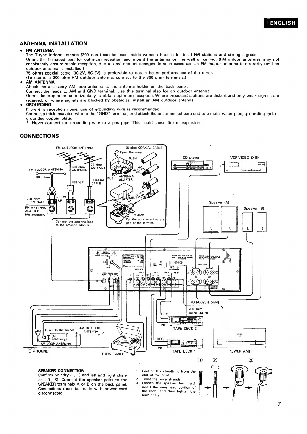
7
WARNING:
As
the
colours
of
the
wires
in
the
mains
lead
of
this
appliance
may
not
correspond
with
the
coloured
markings
identifying
the
terminals
in
your
plug
proceed
as
follows:
The
wire
which
is
coloured
blue
must
be
connected
to
the
terminal
which
is
marked
with
the
letter
N
or
coloured
black.
The
wire
which
is
coloured
brown
must
be
connected
to
the
terminal
which
is
marked
with
the
letter
L
or
coloured
red.
IMPORTANT
The
wires
in
this
mains
lead
are
coloured
in
accordance
with
the
following
code:
Blue:
Neutral
Brown:
Live
Die
Deutsche
Bundespost
informiert
Sehr
geehrter
Rundfunktelinehmer,
Dieses.
Gerait
ist
von
der
Deutschen
Bundespost
als
Ton-
bzw.
Fernseh-Rundfunkempfanger
2ugelassen.
Es
entspricht
den
zur
Zeit
geitenden
Technischen
Vorschriften
der
Deutschen
Bundespost
und
ist
zum
Nachweis
dafur
mit
der
DBP-Prifnummer.....gekennzeichnet.
Bitte
Uberzeugen
Sie
sich
selbst.
Dieses
Gertit
dar!
im
Rahmen
der
nachstehend
abgedruckten »Allgemeinen
Genehmigung
fur
Ton-
und
Fernseh-
Rundfunkempfinger«
in
der
Bundesrepublik
Deutschland
betreben
werden.
Beachten
Sie
aber
bitte,
da&
aufgrund
dieser
Aligerneinen
Genehmigung
nur
Sendungen
des
Rundfunks
empfangen
werden
durten.
*)
Wer
unbefugt
andere
Sendungen
(2.8.
des
Polzeitunks,
des
Seefunks,
der
dffentlichen
beweglichen
Landfunkdienste)
empfangt.
versté8t
gegen
die
Genehmigungsauflagen
und
macht
sich
daher
nach
§
15
Absatz
2a
des
Gesetzes
Uber
Fern-
meideantagen
stratbar.
Die
Kennzeichnung
mit
der
OBP-Prufnummer
bietet
Ihnen
die
Gewahr,
dak
dieses
Gerat
keine
anderen
Fern-
meldeanlagen
einschheGlich
Funkanlagen
stort.
Die
Zusatzbuchstaben
S
SE
oder
SK
be:
der
DBP
Prifnummer
besagen
auRerdem,
da®
das
Gerat
gegen
stérende
Beeinflussungen
durch
andere
Funkanlagen
(2.8.
des
Amateur-
funks,
des
CB-Funks)
wertgehend
unempfindlich
ist.
Sollten
ausnahmsweise
trotzdem
Storungen
auftreten,
so
wenden
Sie
sich
bitte
an
die
ortlich
zusténdige
Funkstérungsmesstelle.
Allgemeine
Genehmigung
fir
Ton-
und
Fernseh-Rundfunkempfanger
Die
Aligemeine
Ton-
und
Fernseh-Rundfunkgenehmigung
vom
11.12.1970
(veroffenticht
im
Bundesanzeiger
Nr.
234
vom
16.12.1970)
wird
unter
Bezug
auf
Abschnutt
tll
der
Genehmigung
durch
folgende
Fassung
der
Aligemeinen
Genehmigung
fiir
Ton-
und
Femseh-Rundfunkemptanger
gema&
den
$5
1
und
2
des
Gesetzes
uber
Fernmeideamagen
ersetzt.
Genehmigung
fiir
Ton-
und
Fernseh-Rundtunkemptinger
i}
1.
Die
Errichtung
und
der
Betneb
von
Ton-
und
Fernseh-Rundtunkempfangern
werden
nach
$§
1
und
2
des
Gesetzes
Uber
Fernmeldeanlagen
in
der
Fassung
det
Bekanntmachung
vom
17.3.1977
(BGBI.
1,
S.
459)
allge-
mein
genehmigt.
2.
Ton:
und
Femnseh-Rundtunkempfinger
im
Sinne
dieser
Genehmigung
sind
Funkanlagen
gema®
$
1
Abs.
|
des
Gesetzes
uber
Fernmeideaniagen,
die
ausschleflich
die
fir
Rundiunkempténger
zugelassenen
Frequen-
zabstimmbereiche®*)
aufwersen
und
zum
Aufnehmen
und
glerchzertigen
Hér-
oder
Sichtbarmachen
von
Ton-
oder
Fernseh-Rundtunksendungen
bestimmt
sind.
Zum
Empfiinger
gehdren
auch
emgebaute
oder
mit
thn
fest
verbundene
Antennen
sowie
bei
Unterteilung
in
mebrere
Gertte
die
funktionsmafig
zugehdrenden
Gerate.
AuBer
fir den
Emptang
von
Rundtunksendungen
dirfen
Ton-
und
Fermseh-Rundfunkemptanger
nur
mit
beson-
derer
Genehmigung
der
Deutschen
Bundespost
fur
andere
Fernmeidezwecke
zusatzhch
benutt
werden.
tn
den
Emopfinger
eingebaute
oder
sonst
mit
ihm
verbundene
Zusatzgerste
{z.B.
Uttraschalitemmeldeanlagen,
infrarotfernmeldeanlagen)
werden
von
dieser
Genehmigung
nicht
erfait
(ausgenommen
die
Emnnchtungen
zum
Empfang
des
Verkehrsrundtunks).
Desgleichen
sind
andere
technische
Emptangereigenschaften.
die
Uber
den
ergentlichen
Zweck
eines
Rundtunkemptangers
hinausgehen
(2.8.
zum
Empfang
anderer
Funkdienste.
fur
die
Wiedergabe
im
Rahmen
von
Textibertragungsverfahren)
hierdurch
nicht
genehmigt
Hiertir
gelten
besondere
Regetungen
u
Diese
Genehmgung
witd
unter
nachstehenden
Autlagen
erteut
1.
Tor
und
Femseh-Rundfunkempfinger
missen
den
jeweils
geltenden
Technischen
Vorschntten
fir
Ton-
und
Fernseh-Rundtunkempfanger
entsprechen.
Eingebaute
Zusatzgerate
mussen
den
fur
ste
geltenden
Bestim-
mungen
und
technischen
Vorschriften
geniigen.
Anderungen
der
Technischen
Vorschriften,
die
im
Amtsbiatt
des
Bundesmuinisters
fur
das
Post-
und
Fernmel-
dewesen
veritfentlicht
werden,
mu&
bei
schon
errichteten
und
in
Betneb
genommenen
Ton-
und
Fernseh-
Rundfunkempfiingern
nachgekommen
werden,
wenn
durch
den
Betneb
dieser
Rundtunkemplanger
andere
elek-
trische
Aniagen
gestért
werden,
Serienmaftig
hergestelite
Ton-
und
Fernseh-Rundiunkempfanger
mussen
zum
Nachweis
dafur,
da@
sie
den
Technischen
Vorschriften
entsprechen,
mit
emer
DBP-Prifnummer
gekennzerchnet
sein.***)
Dre
DBP-Prifnum-
mer
sagt
Uber
die
elektrische
und
mechanische
Sicherheit
und
die
Einhattung
der
Strahlenschutzbestimmungen
nichts
aus.
-
2.
Ton
und
Fernseh-Rundfunkempfanger
diirfen
an
ortsfesten
oder
nichtortstesten
Rundfunk-Emptangsanten-
nenaniagen,
-Verteilaniagen
oder
Kabelfernsehanlagen
betrieben
und
im
Rahmen
der
Bestrmmungen
Uber
private
Drahtfernmeideaniagen
mit
Drahtfernmeideanlagen
verbunden
werden
Auf
demselben
Grundstick
oder
innerhalb
eines
Fahrzeuges
durfen
Ton-
und
Fernseh-Rundfunkemptinger
mit
anderen
Geraten
oder
sonstigen
Gegenstanden
(z.B.
Plattenspieler,
Magnetaulzeichnungs-
und
-Wiedergabeger-
te.
Antennen)
verbunden
werden,
sofern
diese
Gerate
von
der
Deutschen
Bundespost
genehmigt
sind
oder
kemner
Genehmigung
bedirten
Die
raumliche
Kombination
von
Funkaniagen
mit
Ton-
oder
Fernseh-Rundfunkempftangern
ist
nur
dann
zutdssig,
wenn
die
betreffanden
Funkanlagen
je
fur
sich
genehmigt
sind.
3.
Mit
Ton-
oder
Fernseh-Rundfunkemptangern
dirfen
aufgrund
dieser
Genehrgung
.nur
Sendungen
des
Rundfunks
empfangen
werden.
also
Ubertragene
Tonsignate
(Musik,
Sprache)
und
Fernsehsignale
(nur
Bildinfor-
mationen).
Andere
Sendungen
(z.8.
des
Polizeifunks,
der
offenthchen
beweglichen
Landfunkdrenste,
Datenuber-
tragungen)
dirfen
nicht
aufgenommen
werden,
werden
sie
jedoch
unbeabsichugt
empfangen,
so
dirfen
sie
weder
aufgezeichnet,
noch
anderen
mutgeteilt,
noch
fur
irgendwelche
Zwecke
ausgewertet
werden.
Das
Vorhan-
densein
solcher
Sendungen
dart
auch
micht
anderen
zur
Kenntnis
gebracht
werden
4
Durch
Ton-
oder
Fernseh-Rundfunkemptanger
darf
der
Betrieb
anderer
elektrischer
Anlagen
nicht
gestort
wer
den
5
Anderungen
der
Ton-
oder
Fernseh-Rundfunkemptanger,
die die
zulassigen
Frequenzabstimmbereche
der
Emplanger
erweitern,
gehen
Uber
den
Umfang
dieser
Genehmigung
hinaus
und
bedirfen
vor
ihrer
Ausfuthrung
emer
besonderen
Genehmigung
der
Deutschen
Bundespost
Wer
aufgrund
dieser
Genehmigung
einen
Ton-
oder
Fernseh-Rundfunkempfanger
betreibt,
hat
ber
einer
Anderung
der
kennzerchnenden
Merkmale
von
Ton-
oder
Fernseh-Rundfunksendem
{insbesondere
be:
Andewng
des
Sendevertahrens
oder
be:
Frequenzwechsel)
die
gaf.
notwendig
werdenden
Anderungen
an
den
Rundfun-
kempfangern
auf
seine
Kosten
vornehmen
zu
lassen
6.
Die
Deutsche
Bundespost
ist
berechugt,
Rundfunkempfanger
und
mit
ihnen
verbundene
Gerate
daraut
zu
pru:
fen.
ob
die
Auflagen
der
Genehmigung
und
die
Technischen
Vorschniiten
eingehalten
werden
Den
Beauftragten
der
Deutschen
Bundespost
tst
das
Betreten
der
Grundstucke
oder
Raume,
in
denen
sich
Ton-
oder
Fernseh-Rundfunkempfanger
befinden,
zu
den
verkehrsiblichen
Zeiten
zu
gestatten.
Befinden
sich
die
Rundfunkempfanger
oder
mit
ihnen
verbundene
Gerate
nicht
im
Verlugungsbereich
desjenigen,
der
die
Empianger
betreibt,
so
hat
er
den
Beauftragten
der
Deutschen
Bundespost
Zutritt
zu
diesen
Tetlen
2
ermog-
lichen
it
Be:
Funkstérungen
die
nicht
durch
Mangei
der
Rundtunkemphinger
oder
der
mit
shnen
verbundenen
Gerite
verur-
sacht
werden,
konnen
die
FunkmeRdienste
der
Deutschen
Bundespost
zur
Feststellung
der
Strung
in
Anspruch
genommen
werden.
Vv
1.
Diese
Genehmigung
kann
aligemein
oder
durch
die
orthch
zustandige
Oberpostdirektion
einem
einzenen
Bet
reiber
gegenuber
fUr
einen
bestimmten
Rundfunkemptanger
widerrufen
werden.
Ein
Widerruf
ist
insbksondere
zulassig.
wenn
die
unter
Abschnitt
II
aufgefuhrten
Auflagen
nicht
erfullt
werden
Anstatt
die
Genehmigung
zu
widerrufen,
kann
die
Deutsche
Bundespost
anordnen,
dals
bei
einem
Verstos
gegen
eine
Autlage
ein
Ton-
oder
Fernseh-Rundfunkemptanger
aufer
Betneb
zu
setzen
‘st
und
erst
be
Einhal-
tung
der
Aufilagen
wieder
betrieben
werden
darf
Die
Auflagen
dieser
Genehmigung
kénnen
jederzert
erganzi
oder
geandert
werden.
2.
Diese
Genehmigung
ersetzt
die
Aligemeine
Ton-
und
Fernseh-Rundfunkgenehmigung
vorn
11
12.197).
sve
gilt
ab
1.7.1979.
Bonn,
den
14.5.1979
Der
Bundesminister
fur
das
Post-
und
Fernmekdewesen
Im
Auftrag,
Hast
*)
Zum
Emptang
anderer
Sendungen
dart
dieses
Gert
nur
mit
Genehmigung
der
Deutschen
Bundespost
benutzt
werden.
Aligemein
genehmigt
ist
zur
Zeit
der
Empfang
der
Aussendungen
von
Amateurfunkstellen
und
deiNormal
frequenz:
und
Zeitzeichensendungen.
**)
Siehe
Technische
Vorschnften
fiir
Ton-
und
Fernseh-Rundfunkemptinger.
verdtfenthicht
im
Amtsblatt
des
Bundesministers
fir
das
Post-
und
Femmeldewesen.
***)
Fur
ausnahmsweise
noch
nicht
gekennzeichnete,
vor
dem
1.7.1979
emichtete
und
in
Betrieb
genommene
Ton-Rundfunkempfanger
wird
die
Kennzeichnung
nicht
venangt