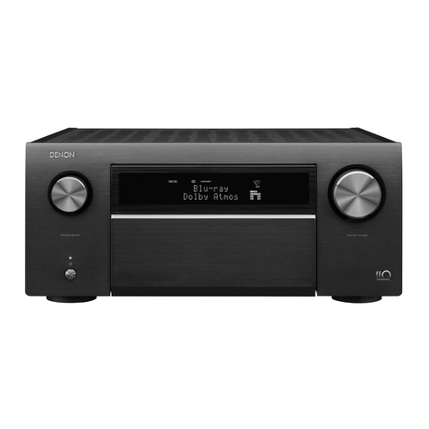
Denon RCD-M33 User manual

SERVICE MANUAL
STEREO CD RECEIVER
MODEL RCD-M35DAB
RCD-M33
TOKYO, JAPAN
Denon Brand Company, D&M Holdings Inc.
X0230V.02 DE/CDM 0510
Some illustrations using in this service manual are
slightly different from the actual set.
●
Please use this service manual with referring to the
operating instructions without fail.
●
For purposes of improvement, specifications and
design are subject to change without notice.
●
●
本文中に使用しているイラストは、説明の都合上現物
と多少異なる場合があります。
●
修理の際は、必ず取扱説明書を参照の上、作業を行っ
てください。
サービスをおこなう前に、このサービスマニュアルを
必ずお読みください。本機は、火災、感電、けがなど
に対する安全性を確保するために、さまざまな配慮を
おこなっており、また法的には「電気用品安全法」に
もとづき、所定の許可を得て製造されております。
従ってサービスをおこなう際は、これらの安全性が維
持されるよう、このサービスマニュアルに記載されて
いる注意事項を必ずお守りください。
●
本機の仕様は性能改良のため、予告なく変更すること
があります。
●
補修用性能部品の保有期間は、製造打切後8年です。
注 意
For U.S.A., Canada, Europe,
U.K. & Japan model
Ver. 2
Please refer to the
MODIFICATION NOTICE.
w
w
w
.
x
i
a
o
y
u
1
6
3
.
c
o
m
Q
Q
3
7
6
3
1
5
1
5
0
9
9
2
8
9
4
2
9
8
T
E
L
1
3
9
4
2
2
9
6
5
1
3
9
9
2
8
9
4
2
9
8
0
5
1
5
1
3
6
7
3
Q
Q
TEL 13942296513 QQ 376315150 892498299
http://www.xiaoyu163.com
2
RCD-M35DAB/M33
Please heed the points listed below during servicing and inspection.
◎Heed the cautions!
Spots requiring particular attention when servicing, such as
the cabinet, parts, chassis, etc., have cautions indicated on
labels or seals. Be sure to heed these cautions and the cau-
tions indicated in the handling instructions.
◎Caution concerning electric shock!
(1) An AC voltage is impressed on this set, so touching inter-
nal metal parts when the set is energized could cause
electric shock. Take care to avoid electric shock, by for ex-
ample using an isolating transformer and gloves when
servicing while the set is energized, unplugging the power
cord when replacing parts, etc.
(2)There are high voltage parts inside. Handle with extra care
when the set is energized.
◎
Caution concerning disassembly and assembly!
Though great care is taken when manufacturing parts from
sheet metal, there may in some rare cases be burrs on the
edges of parts which could cause injury if fingers are moved
across them. Use gloves to protect your hands.
◎Only use designated parts!
The set's parts have specific safety properties (fire resis-
tance, voltage resistance, etc.). For replacement parts, be
sure to use parts which have the same properties. In particu-
lar, for the important safety parts that are marked ! on wiring
diagrams and parts lists, be sure to use the designated parts.
◎Be sure to mount parts and arrange the
wires as they were originally!
For safety reasons, some parts use tape, tubes or other insu-
lating materials, and some parts are mounted away from the
surface of printed circuit boards. Care is also taken with the
positions of the wires inside and clamps are used to keep
wires away from heating and high voltage parts, so be sure to
set everything back as it was originally.
◎Inspect for safety after servicing!
Check that all screws, parts and wires removed or discon-
nected for servicing have been put back in their original posi-
tions, inspect that no parts around the area that has been
serviced have been negatively affected, conduct an insulation
check on the external metal connectors and between the
blades of the power plug, and otherwise check that safety is
ensured.
(Insulation check procedure)
Unplug the power cord from the power outlet, disconnect the
antenna, plugs, etc., and turn the power switch on. Using a
500V insulation resistance tester, check that the insulation re-
sistance between the terminals of the power plug and the ex-
ternally exposed metal parts (antenna terminal, headphones
terminal, microphone terminal, input terminal, etc.) is 1MΩor
greater. If it is less, the set must be inspected and repaired.
Concerning important safety parts
Many of the electric and structural parts used in the set have
special safety properties. In most cases these properties are
difficult to distinguish by sight, and using replacement parts
with higher ratings (rated power and withstand voltage) does
not necessarily guarantee that safety performance will be pre-
served. Parts with safety properties are indicated as shown
below on the wiring diagrams and parts lists is this service
manual. Be sure to replace them with parts with the designat-
ed part number.
(1) Schematic diagrams ... Indicated by the ! mark.
(2) Parts lists ... Indicated by the ! mark.
Using parts other than the designated parts
could result in electric shock, fires or other
dangerous situations.
SAFETY PRECAUTIONS
The following check should be performed for the continued protection of the customer and service technician.
LEAKAGE CURRENT CHECK
Before returning the unit to the customer, make sure you make either (1) a leakage current check or (2) a line to chassis
resistance check. If the leakage current exceeds 0.5 milliamps, or if the resistance from chassis to either side of the power
cord is less than 460 kohms, the unit is defective.
LASER RADIATION
Do not stare into beam or view directly with optical instruments, class 3A laser product.
CAUTION
CAUTION
サービス、点検時にはつぎのことにご注意願います。
◎注意事項をお守りください!
サービスのとき特に注意を必要とする個所についてはキャ
ビネット、部品、シャーシなどにラベルや捺印で注意事項を
表示しています。これらの注意書きおよび取扱説明書などの
注意事項を必ずお守りください。
◎感電に注意!
(1) このセットは、交流電圧が印加されていますので通電時
に内部金属部に触れると感電することがあります。従っ
て通電サービス時には、絶縁トランスの使用や手袋の着
用、部品交換には、電源プラグを抜くなどして感電にご
注意ください。
(2) 内部には高電圧の部分がありますので、通電時の取扱に
は十分ご注意ください。
◎分解、組み立て作業時のご注意!
板金部品の端面の『バリ』は、部品製造時に充分管理をして
おりますが、板金端面は鋭利となっている箇所が有りますの
で、部品端面に触れたまま指を動かすとまれに怪我をする場
合がありますので十分注意して作業して下さい。手の保護の
ために手袋を着用してください。
◎指定部品の使用!
セットの部品は難燃性や耐電圧など安全上の特性を持った
ものとなっています。従って交換部品は、使用されていたも
のと同じ特性の部品を使用してください。特に配線図、部品
表に!印で指定されている安全上重要な部品は必ず指定の
ものをご使用ください。
◎部品の取付けや配線の引きまわしは、
元どおりに!
安全上、テープやチューブなどの絶縁材料を使用したり、プ
リント基板から浮かして取付けた部品があります。また内部
配線は引きまわしやクランパーによって発熱部品や高圧部
品に接近しないように配慮されていますので、これらは必ず
元どおりにしてください。
◎サービス後は安全点検を!
サービスのために取り外したねじ、部品、配線などが元どお
りになっているか、またサービスした個所の周辺を劣化させ
てしまったところがないかなどを点検し、外部金属端子部
と、電源プラグの刃の間の絶縁チェックをおこなうなど、安
全性が確保されていることを確認してください。
(絶縁チェックの方法)
電源コンセントから電源プラグを抜き、アンテナやプラグな
どを外し、電源スイッチを入れます。500V 絶縁抵抗計を用
いて、電源プラグのそれぞれの端子と外部露出金属部[アン
テナ端子、ヘッドホン端子マイク端子、入力端子など]との
間で、絶縁抵抗値が1 MΩ 以上であること、この値以下の
ときはセットの点検修理が必要です。
安全上重要な部品について
本機に使用している多くの電気部品、および機構部品は安全
上、特別な特性を持っています。この特性はほとんどの場合、
外観では判別つきにくく、またもとの部品より高い定格(定
格電力、耐圧)を持ったものを使用しても安全性が維持され
るとは、限りません。安全上の特性を持った部品は、この
サービスマニュアルの配線図、部品表につぎのように表示し
ていますので必ず指定されている部品番号のものを使用願
います。
(1) 配線図…!マークで表示しています。
(2) 部品表…!マークで表示しています。
指定された部品と異なるものを使用した場合に
は、感電、火災などの危険を生じる恐れがあり
ます。
注 意
注 意
w
w
w
.
x
i
a
o
y
u
1
6
3
.
c
o
m
Q
Q
3
7
6
3
1
5
1
5
0
9
9
2
8
9
4
2
9
8
T
E
L
1
3
9
4
2
2
9
6
5
1
3
9
9
2
8
9
4
2
9
8
0
5
1
5
1
3
6
7
3
Q
Q
TEL 13942296513 QQ 376315150 892498299
http://www.xiaoyu163.com

3
RCD-M35DAB/M33
CAUTION IN SERVICING
Initializing RCD-M35DAB/M33
RCD-M35DAB/M33 initialization should be performed when the
µcom, and peripheral parts of µcom are replaced.
1. Switch off the unit and remove the AC cord from the wall out-
let.
2. Hold the following button and MENU/SET button,
and plug the AC cord into the outlet.
Note: All user settings will be lost and this factory setting will
be recovered when this initialization mode.
So make sure to memorize your setting for restoring
after the initialization.
BLOCK DIAGRAM
サービス時の注意事項
本機の初期化について
マイコンやマイコン周辺部品を交換した場合は、本機の初期化
を行って下さい。
1. 電源ボタンを押してスタンバイ状態にしてから、壁の電源
コンセントから電源コードを抜きます。
2. ボタンと MENU/SET ボタンを同時に押しながら、
電源プラグをコンセントに差し込みます。
*マイコンが初期化されます。
注意 : 初期化を行うとお客様が設定した内容が工場出荷状
態に戻りますので、あらかじめ設定内容を控えてお
き初期化後再設定してください。
2
w
w
w
.
x
i
a
o
y
u
1
6
3
.
c
o
m
Q
Q
3
7
6
3
1
5
1
5
0
9
9
2
8
9
4
2
9
8
T
E
L
1
3
9
4
2
2
9
6
5
1
3
9
9
2
8
9
4
2
9
8
0
5
1
5
1
3
6
7
3
Q
Q
TEL 13942296513 QQ 376315150 892498299
http://www.xiaoyu163.com

5
RCD-M35DAB/M33
CD TEST MODE
No Key name Function Display
1
Version No. of
Main MPU Dis-
play Mode
S1
・Plug AC cord into power outlet while pressing
ON/STANDBY Key and SDB/TONE Key same
time on Main Unit.
・The Version number of Main MPU is displayed.
・Unplug AC cord to clear this mode.
・Upper : "_ _ _ _ Ver _ * * * * _ _ _ _"
"****" is the Version number of Main MPU
・Lower : "_ _ _ _ _ _ _ _ _ _ _ _ _ _ _ _"
2FLD(VFD) check-
ing mode
S2
・Plug AC cord into power outlet while pressing
ON/STANDBY Key and OPEN/CLOSE Key
same time on Main Unit.
・All segment of FLD is turning on and off every
one second.
・Unplug AC cord to clear this mode.
・All segment turn on and off.
3EEPROM testing
Mode
S3
・Plug AC cord into power outlet while pressing
ON/STANDBY Key and STOP/BAND Key same
time on Main Unit.
・POWER LED illuminant Orange to sign the test
mode started.
・When power LED lighted GREEN, this EEPROM
test was OK.
・When power LED lighted RED, this EEPROM test
was NG.
・Unplug AC cord to clear this mode.
4
DAB Function
CHECK Mode.
(This test for only
RCD-
M35DABSREK)
・Plug AC cord into power outlet while pressing
MENE/SET Key and Key same time on
Main Unit.
・Turn the power on then set the volume level to 25
(-18dB).
・Set the function to "TUNER", the band to "DAB".
・Enable service reception without conducting DAB
auto scanning.
(After about 10 to 15 seconds)
(Without auto scanning) Receive frequency
12C : 227.360MHz
(Without switching the DISPLAY key) Signal
quality display
・Unplug AC cord to clear this mode.
5 CD service mode
・Plug AC cord into power outlet while pressing
ON/STANDBY Key and FUNCTION Key same
time on Main Unit.
・Move the slide to the initially set position (10 mm
towards the outside from the innermost position).
・Check by performing key input. Refer to 5.1 to
5.6.
・Cancel the mode by turning the power back on.
・Input of keys other than those used in this mode
is not guaranteed. (OK if malfunction occurs)
・ flashing
・Upper : "_ 00 _ CD_Ver _ * * * * _" displayed
**** : CD microprocessor version no.
・Lower : "_ _ _ _ _ _ _ _ _ _ _ _ _ _ _ _"
5.1 Disc loading
・Press the CD OPEN/CLOSE key to open the tray.
・Set a disc on the tray, then press the CD OPEN/
CLOSE key again to close the tray. The disc is
mounted automatically.
・Move the slide to the initially set position (10 mm
towards the outside from the innermost position)
and stop in this status.
Continue S6 display
CD テストモード
No キー名称 機能 表記
1メインマイコンバージョン
表示モード
S1
・本体 ON/STANDBY キーと SDB/TONE キーを同時に
押しながら、AC コードをコンセントへ接続する .
・メインマイコンの Ver を表示する.MUTINGON.
・AC コードを抜くことによりモードを解除する.
・上段:"Ver****"表示
****:メインマイコンの Ver 番号
・下段:""
2FL(VFD) 管
チェックモード
S2
・本体 ON/STANDBY キーと CDOPEN/CLOSE キーを
同時に押しながら、AC コードをコンセントへ接続す
る.
・FL 管の全てを 2 秒周期で点滅 (1 秒点灯、1 秒
消灯 ) する.MUTINGON.
・AC コードを抜くことによりモードを解除する.
・全てのセグメントを点灯・消灯する.
3EEPROMTEST
モード
S3
・本体 ON/STANDBY キーと CDSTOP/BAND キーを同
時に押しながら、AC コードをコンセントへ接続する.
・POWERLED が橙色に点灯する (TEST 開始 ).
MUTINGON.
・EEPROMTEST 後、OK の時は、緑色に点灯す
る.
・EEPROMTEST 後、NG の時は、赤色に点灯す
る.
・AC コードを抜くことによりモードを解除する.
4
DABCHECK モード
(onlyRCD-
M35DABSREK)
・本体 MENU/SET キーと キーを同時に押しな
がら、AC コードをコンセントへ接続する.
・POWERON 後、VOLLEVEL を 25(-18dB) とす
る.
・Function を TUNER、 BAND を DAB にする。
・DAB の AUTOSCAN を行わずにサービスの受信が
可能となる.
(約 10 〜 15 秒後)
(AUTOSCAN せずに)周波数 12C:
227.360MHz を受信.
(DISPLAY キー切り替えずに)SignalQuality 表
示.
・AC コードを抜くことによりモードを解除する.
5 CD サービスモード
・本体 ON/STANDBY キーと FUNCTION キーを同時に
押しながら、AC コードをコンセントへ接続する.
・スライドを初期設定位置に移動する.(最内周か
ら外側 10mm の位置)
・キー入力によりチェックを行う. 5.1 〜 5.6 参照.
・電源の再投入によりモードを解除する.
・このモードで使用するキー以外の入力は保証しな
い.(異常な動作になってもよしとする)
・ を点滅
・上段:"00CDVer****"表示
****:CD マイコンの Ver 番号
・下段:""
5.1 ディスク装着
・CDOPEN/CLOSE キーでトレイを開く.
・ディスクを置き、再度 CDOPEN/CLOSE キーでトレイを
閉じるとディスクをチャッキングする.
・スライドを初期設定位置(最内周から外側
10mm の位置)に移動し、その状態でストップ
する.
S6 の表示を継続する.
w
w
w
.
x
i
a
o
y
u
1
6
3
.
c
o
m
Q
Q
3
7
6
3
1
5
1
5
0
9
9
2
8
9
4
2
9
8
T
E
L
1
3
9
4
2
2
9
6
5
1
3
9
9
2
8
9
4
2
9
8
0
5
1
5
1
3
6
7
3
Q
Q
TEL 13942296513 QQ 376315150 892498299
http://www.xiaoyu163.com
6
RCD-M35DAB/M33
5.2 Servo check
・Press the CD PLAY/PAUSE key. Execute the
following steps.
①LD ON (with servo still stopped)
②FOCUS ON (disc rotation, tracking off)
If no disc loaded, retry then stop.
③CLV ON
④TRACKING ON
⑤SUB CODE readout (playback sound output)
⑥When display is as in ⑤and the PLAY button
is pressed, conduct BER (Block Error Rate)
display for 2 seconds. (Display total no.
generated in 10 seconds.)
*Press PLAY button continuously for over 1
second to switch directly to SUB CODE
readout in step ⑤.
・ flashing
①
・Upper : " 01 _ _ _ _ __ LD_ON _" displayed
・Lower : "_ _ _ _ _ _ _ _ _ _ _ _ _ _ _ _"
②
・Upper : " _ 02 _ _ _ _ Focus_ON _" displayed
③
・Upper : "_ 03 _ _ _ _ _ _ CLV_ON _" displayed
④
・Upper : "_ 04 _ Tracking_ON _" displayed
⑤
・Upper : "_ 05 _ _ _ @@Tr _ _ XX:XX" displayed
@@ : T.No
XX:XX : Time
⑥
・Upper : "_ _ _ _ _ _ ERR _ ######" displayed
###### : B.E.R.
5.3 Pickup movement
・In the stop mode, pickup moves in REV (inwards)
or FWD (outwards) direction when key
or key pressed.
・When key pressed, move to stop
operation after detection that inner switch has
turned on.
・Pickup movement stops when key released.
(Pickup moves while key is pressed.)
Continuous display of previous time
5.4 Stop
・When STOP key is pressed, play operation and
servo stop.
・
After stopping, conduct reading of auto adjust values.
・Same as 5.
5.5 All servo on
・When MENU/SET key is pressed, all servos turn
on, auto adjustment is performed and switch to
playback operation. (Playback sound output)
・ flashing
・Upper : "_ _ _ _ _ _ @@Tr _ _ XX:XX" displayed
@@ : T.No
XX:XX : Time
・Lower : "_ _ _ _ _ _ _ _ _ _ _ _ _ _ _ _"
No Key name Function Display
5.2 サーボチェック
・CDPLAY/PAUSE キーを押すと下記ステップを実行
する.
①LDON( サーボ停止のまま )
②FOCUSON( ディスク回転、トラッキング OFF)
ディスク無しの場合、リトライ後停止する.
③CLVON
④TRACKINGON
⑤SUBCODE 読み出し(再生音出力)
⑥⑤の表示時に PLAY ボタンを押すと、2 秒間
BER(BlockErrorRate) の表示を行なう.
(10 秒間の間に発生した総数を表示)
* PLAY ボタンの 1 秒以上押し続けにて、ダイレクト
に⑤の SUBCODE 読み出しステップに移行する.
・ を点滅
①
・上段:"01LDON"表示
・下段:""
②
・上段:"02FocusON"表示
③
・上段:"03CLVON"表示
④
・上段:"04TrackingON"表示
⑤
・上段:"05@@TrXX:XX"表示
@@:T.No
XX:XX:時間
⑥
・上段:"ERR######"表示
######:B.E.R.
5.3 ピックアップ移動
・ストップ状態で キーまたは キーを押す
と、ピックアップが REV( 内周側 ) または FWD( 外
周側 ) 方向に移動する.
・ キーを押した時は、内周 SW の ON を検
出後ストップ動作に移行する.
・キーを離すとピックアップの移動を停止する.( キーが
押されている間、移動する.)
前回の表示を継続する.
5.4 停止
・STOP キーを押すと、PLAY 動作及びサーボを停止
する.
・停止後、自動調整値の読込みを行なう.
・5 と同じ.
5.5 全サーボ ON
・MENU/SET キーを押すと全サーボを ON し、自動
調整を行なって再生動作に移行する.(再生音
出力)
・ を点滅
・上段:"@@TrXX:XX"表示
@@:T.No
XX:XX:時間
・下段:""
No キー名称 機能 表記
w
w
w
.
x
i
a
o
y
u
1
6
3
.
c
o
m
Q
Q
3
7
6
3
1
5
1
5
0
9
9
2
8
9
4
2
9
8
T
E
L
1
3
9
4
2
2
9
6
5
1
3
9
9
2
8
9
4
2
9
8
0
5
1
5
1
3
6
7
3
Q
Q
TEL 13942296513 QQ 376315150 892498299
http://www.xiaoyu163.com

7
RCD-M35DAB/M33
5.6 Adjustment value
display
・When SDB/TONE key is pressed, the adjustment
values are displayed in the following order.
①FOCUS BALANCE
②FOCUS GAIN
③TRACKING BALANCE
④TRACKING GAIN
⑤FOCUS OFFSET
⑥TRACKING OFFSET
⑦RFRP
⑧Return to ①.
(NOTE)If auto adjustment is not completed,
proper values are not displayed.
・ flashing
①
・Upper : "FOCUS _ BALANCE _ _ _"
・Lower : "XX _ _ _ _ _ _ _ _ _ _ _ _ _ _"
・XX : Adjustment value
②
・Upper : "FOCUS _ GAIN _ _ _ _ _ _"
・Lower : "XX _ _ _ _ _ _ _ _ _ _ _ _ _ _"
・XX : Adjustment value
③
・Upper : "TRACKING _ BALANCE"
・Lower : "XX _ _ _ _ _ _ _ _ _ _ _ _ _ _"
・XX : Adjustment value
④
・Upper : "TRACKING _ GAIN _ _ _"
・Lower : "XX _ _ _ _ _ _ _ _ _ _ _ _ _ _"
・XX : Adjustment value
⑤
・Upper : "FOCUS _ OFFSET _ _ _ _"
・Lower : "XX _ _ _ _ _ _ _ _ _ _ _ _ _ _"
・XX : Adjustment value
⑥
・Upper : "TRACKING _ OFFSET _"
・Lower : "XX _ _ _ _ _ _ _ _ _ _ _ _ _ _"
・XX : Adjustment value
⑦
・Upper : "RFRP _ _ _ _ _ _ _ _ _ _ _ _"
・Lower : "XX _ _ _ _ _ _ _ _ _ _ _ _ _ _"
・XX : Adjustment value
No Key name Function Display
5.6 調整値の表示
・SDB/TONE キーを押すと、下記の順番で調整値
を表示する.
① FOCUSBALANCE
② FOCUSGAIN
③ TRACKINGBALANCE
④ TRACKINGGAIN
⑤ FOCUSOFFSET
⑥ TRACKINGOFFSET
⑦RFRP
⑧①に戻る。
( 注 ) 自動調整を終了して無い場合は正常な値が
表示されない.
・ を点滅
①
・上段:"FOCUSBALANCE"
・下段:"XX"
・XX:調整値
②
・上段:"FOCUSGAIN"
・下段:"XX"
・XX:調整値
③
・上段:"TRACKINGBALANCE"
・下段:"XX"
・XX:調整値
④
・上段:"TRACKINGGAIN"
・下段:"XX"
・XX:調整値
⑤
・上段:"FOCUSOFFSET"
・下段:"XX"
・XX:調整値
⑥
・上段:"TRACKINGOFFSET"
・下段:"XX"
・XX:調整値
⑦
・上段:"RFRP"
・下段:"XX"
・XX:調整値
No キー名称 機能 表記
w
w
w
.
x
i
a
o
y
u
1
6
3
.
c
o
m
Q
Q
3
7
6
3
1
5
1
5
0
9
9
2
8
9
4
2
9
8
T
E
L
1
3
9
4
2
2
9
6
5
1
3
9
9
2
8
9
4
2
9
8
0
5
1
5
1
3
6
7
3
Q
Q
TEL 13942296513 QQ 376315150 892498299
http://www.xiaoyu163.com

8
RCD-M35DAB/M33
6 CD heat run mode
・Plug AC cord into power outlet while pressing
ON/STANDBY Key and MENU/SET Key same
time on Main Unit.(Be sure to insert the CD
before this operation)
・Switches to mode according to key input.
See 6.1 and 6.2.
・If an error occurs, display the error and stop
operation at that point. Number of operations
held. See 6.3 to 6.5.
・Heat run no. cleared when STOP key pressed.
・Mode canceled and tray opened after CD OPEN/
CLOSE key pressed.
・Unplug AC cord to clear this mode too.
・lit
・Normal display except when lit.
6.1 Normal heat run
mode
・After CD heat run mode has started, press the
CD PLAY/PAUSE key.(Be sure to finish reading
the TOC before push CD PLAY/PAUSE key)
Count this as the 0th heat run repetition.
①Play from the first to last track on disc.
②If disc being used has less than 20 tracks, play
all tracks. If disc has 21 or more tracks, skip to
final track after playback of first track has
finished.
③After disc playback has finished, move pickup
to innermost position and open tray.
④When loader open status detected, close tray
again, re-read TOC and start playback from
the first track on the disc.
⑤The heat run repetition no. is incremented
(increased by 1) when the tray is opened.
⑥Conduct ①to ⑤repeatedly.
・lit
①,②
・In cases other than when is lit, same display as
during normal playback.
③
・Upper : "_ CD _ _ _ _ _ _ _ _ XXXX_"
・Lower : "_ _ _ _ _ _ _ _ _ _ _ _ _ _ _ _"
・XXXX : No. of heat run repetitions
④
・Upper : "_ CD _ _ _ 01Tr _ _ _ _ : _ _"
・Lower : "_ _ _ _ _ _ _ _ _ _ _ _ _ _ _ _"
6.2 Automatic
mounting mode
・After CD heat run mode has started, press the
CD STOP/BAND key once in the stop mode.(Be
sure to finish reading the TOC before push CD
STOP/BAND key)
・TOC reading ⇒Search for first track on disc ⇒
tray open ⇒tray close ⇒TOC reading ⇒
repeat. No. heat run repetitions displayed on
time display section.
・Increment the heat run repetition no. (increase
by 1) at the point when the loader has finished
opening.
While tray opened
・Same as for regular heat run. See 6.1 ③.
When tray closed
・Same as for regular heat run. See 6.1.
No Key name Function Display
6 CD ヒートランモード
・本体 ON/STANDBY キーと MENU/SET キーを同時に
押しながら、AC コードをコンセントへ接続する.
・キー入力に応じたモードへ移行する.( 必ずディスク
を入れておくこと )
6.1〜6.2参照.
・エラーが発生したら、エラー表示をしてその場で動
作を停止する。動作回数は保持しておく.
6.3〜6.5参照.
・STOP キーを押した場合、ヒートラン回数をクリアする.
・CDOPEN/CLOSE キーが押されたら、モードを解除
してトレイをオープンする.
・AC コードを抜くことでもモードを解除する.
・ を点灯
・ を点灯している以外は通常と同じ表示.
6.1 通常ヒートランモード
・CDヒートランモードが起動した後 CDPLAY/PAUSE キー
を押す.(CDPLAY/PAUSEキーを押す前に、
TOCREAD が完了していること ) この時、
ヒートラン繰り返し回数を 0 回目とする.
①ディスクの先頭トラックから最終トラックまで再生す
る.
②使用ディスクが 20 トラック以内の場合は全トラックを
再生する.21 トラック以上なら1トラック目終了後、
最終トラックにスキップする.
③ディスクの再生終了後、ピックアップを最内周に移
動させトレイを開く.
④ローダー OPEN 状態を検出したら、再度トレイを
閉じ再度 TOC を読み取り後、ディスクの先頭
トラックから再生を開始する.
⑤ヒートラン回数はトレイを OPEN したところで
インクリメント ( ヒートラン回数を 1 つ増やす ) する.
⑥①〜⑤を繰り返し実行する.
・ を点灯
①、②
・ を点灯している以外は通常再生中と同じ表示.
③
・上段:"CDXXXX"
・下段:""
・XXXX:ヒートラン繰り返し回数
④
・上段:"CD01Tr:"
・下段:""
6.2 チャッキングモード
・CDヒートランモードが起動した後、停止中に CD
STOP/BAND キーを 1 回押す.(CDSTOP/BAND
キーを押す前に、TOCREAD が完了しているこ
と)
・TOC 読込み⇒ディスクの先頭トラックをサーチ⇒
トレイ OPEN ⇒トレイ CLOSE ⇒ TOC 読込み⇒を繰り
返す。時間表示部にヒートランの繰り返し回数を表
示する。
・ヒートラン回数はローダーを OPEN し終えたところで
インクリメント (increment:ヒートラン回数を 1 つ増やす )
する.
トレイオープン中
・通常ヒートラン時と同じ. 6.1③を参照
トレイクローズ中
・通常ヒートラン時と同じ. 6.1④を参照
No キー名称 機能 表記
w
w
w
.
x
i
a
o
y
u
1
6
3
.
c
o
m
Q
Q
3
7
6
3
1
5
1
5
0
9
9
2
8
9
4
2
9
8
T
E
L
1
3
9
4
2
2
9
6
5
1
3
9
9
2
8
9
4
2
9
8
0
5
1
5
1
3
6
7
3
Q
Q
TEL 13942296513 QQ 376315150 892498299
http://www.xiaoyu163.com
9
RCD-M35DAB/M33
6.3 Error display
E1-00 : Disc cannot be detected
E1-01 : Tracking offset adjustment not possible
E1-02 : Focus offset adjustment not possible
E2-00 : Focus servo could not follow during
playback
E2-01 : Focus servo could not follow during
searching
E2-03 : Focus servo could not follow during TOC
reading
E2-05 : Focus servo could not follow during
pause
E2-10 : Subcode can no longer be read during
playback
E2-11 : Subcode can no longer be read during
searching
E2-12 : Subcode can no longer be read during
TOC reading
E2-14 : Subcode cannot be read during pause
E2-15 : Subcode cannot be read during manual
search
E3-00 : TOC could not be read within specified
time
E3-01 : PVD/SVD analysis could not be
completed within specified time
E4-04 : Search time out (searching not
completed within specified time)
E4-05 : Decoder bus (Error in communications
with CD decoder)
E5-00 : Inner switch not on
E6-00 : Inner switch not off
E9-00 : Error in CD microprocessor
E9-01 : Other error
・lit
・Upper : "_ CD _ _ _ _ _ _ _ _ EX-XX"
・X-XX : Error display
・Lower : "_ _ _ _ _ _ _ _ _ _ _ _ _ _ _ _"
6.4 Error display
switching (1)
・Press the key while the error is
displayed.
・No. heat runs is displayed for 5 seconds, the
error display reappears.
・lit
・Upper : "_ CD _ _ _ _ _ _ _ _ XXXX_"
・Lower : "_ _ _ _ _ _ _ _ _ _ _ _ _ _ _ _"
・XXXX : No. of heat run repetitions
・Error display reappears after 5 seconds. See 6.3.
6.5 Error display
switching (2)
・Press the key while the error is
displayed.
・The track no. and time when the error occurred is
displayed for 5 seconds, then error display
reappears.
・In cases other than when is lit, same display as
during normal playback.
・Error display reappears after 5 seconds. See 6.3.
No Key name Function Display
6.3 エラー表示
E1-00:ディスク検出出来ず
E1-01:トラッキングオフセット調整出来ず
E1-02:フォーカスオフセット調整出来ず
E2-00:再生中フォーカスサーボが追従できなかった
時があった
E2-01:サーチ中フォーカスサーボが追従できなかった時
があった
E2-03:TOC 読み込み中フォーカスサーボが追従でき
なかった時があった
E2-05:ポーズ中フォーカスサーボが追従できなかった
時があった
E2-10:再生中サブコードが読めなくなった
E2-11:サーチ中サブコードが読めなくなった
E2-12:TOC 読み込み中サブコードが読めなく
なった
E2-14:ポーズ中サブコードが読めない
E2-15:マニュアルサーチ中サブコードが読めない
E3-00:Toc 規定時間以内に読めず
E3-01:PVD/SVD 解析規定時間以内に終わらず
E4-04:サーチタイムアウト(サーチが規定時間内に終了しな
かった )
E4-05:デコーダバス (CDDECODER との通信エラー
が発生した )
E5-00:内周 SWON せず
E6-00:内周 SWOFF せず
E9-00:CD マイコンエラーが発生
E9-01:その他のエラーが発生
・ を点灯
・上段:"CDEX-XX"
・X-XX:エラー表示
・下段:""
6.4 エラー表示の切換 (1)
・エラー表示中に キーを押す.
・ヒートラン回数を 5 秒間表示し、エラー表示に戻る.
・ を点灯
・上段:"CDXXXX"
・下段:""
・XXXX:ヒートラン繰り返し回数
・5 秒後にエラー表示に戻る.S6.3 参照
6.5 エラー表示の切換 (2)
・エラー表示中に キーを押す.
・発生時のトラック番号と時間を 5 秒間表示しエラー表
示に戻る.
・ を点灯している以外は通常再生中と同様の表
示.
・5 秒後にエラー表示に戻る.S6.3 参照
No キー名称 機能 表記
w
w
w
.
x
i
a
o
y
u
1
6
3
.
c
o
m
Q
Q
3
7
6
3
1
5
1
5
0
9
9
2
8
9
4
2
9
8
T
E
L
1
3
9
4
2
2
9
6
5
1
3
9
9
2
8
9
4
2
9
8
0
5
1
5
1
3
6
7
3
Q
Q
TEL 13942296513 QQ 376315150 892498299
http://www.xiaoyu163.com
12
RCD-M35DAB/M33
SEMICONDUCTORS
Only major semiconductors are shown, general semiconductors etc. are omitted to list.
主な半導体を記載しています。汎用の半導体は記載を省略しています。
1. IC’s
M30624FGPGP (IC802)
M30624FGPGP Terminal Function
Pin
No.
Port
Function
Port
setting Port Name Explanation Output of Standby
& Default
1 P94 O Not Used: N. C. L
2 P93 O FL RESET Reset output to FLD L
3 SOUT3 SO FLDA Serial Data output to FLD L
4 SIN3 O Not Used: N. C. HI-Z
5 CLK3 SO FLCK Serial Clock output to FLD L
6 BYTE (VSS) GND -
7 CNVSS I FLASH CNVss Select input of Flash rom write Mode HI-Z
8 P87 O Not Used: N. C. L
9 P86 O Not Used: N. C. L
10 RESET I RESET Reset input HI-Z
11 XOUT XTAL (16MHz) Xtal output -
12 VSS (VSS) GND -
13 XIN XTAL (16MHz) Xtal input -
14 VCC (VCC) Positive power -
15 NMI I (PullUp) Pull up HI-Z
16 INT2 INT PROTECT/SP PROTECTION Protect Signal input HI-Z
17 INT1 INT CDREQ Interrupt request from CD MPU HI-Z
18 INT0 INT /DBRXD DENON BUS Data input (interrupt input) HI-Z
19 P81 I 50/60 50Hz/60Hz AC Input HI-Z
20 P80 O MREQ Interrupt request to CD MPU L
21 P77 O Not Used: N. C. L
22 P76 O Not Used: N. C. HI-Z
23 TA2IN I VOL JOGB VOL encoder Pulse-B input HI-Z
24 TA2OUT I VOL JOGA VOL encoder Pulse-A input HI-Z
25 P73 O FLCS Chip Enable output to FLD L
26 P72 O MSCLK Serial Clock output from CD MPU L
27 P71 SI MDI Serial Data input from CD MPU L
28 P70 SO MDO Serial Data output to CD MPU L
29 TXD1 SO FLASH TxD DATA BUS (Flash rom write) DATA output L
75
76
1
100
51
50
26
25
w
w
w
.
x
i
a
o
y
u
1
6
3
.
c
o
m
Q
Q
3
7
6
3
1
5
1
5
0
9
9
2
8
9
4
2
9
8
T
E
L
1
3
9
4
2
2
9
6
5
1
3
9
9
2
8
9
4
2
9
8
0
5
1
5
1
3
6
7
3
Q
Q
TEL 13942296513 QQ 376315150 892498299
http://www.xiaoyu163.com

13
RCD-M35DAB/M33
30 P66 SI FLASH RxD DATA BUS (Flash rom write) DATA input HI-Z
31 CLK1 I Pull down L
32 P64 O Not Used: N. C. L
33 TXD0 SI S1_DIN Serial Data input from DAB Module L
34 RXD0 SO S1_DOUT Serial Data output to DAB Module L
35 CLK0 O Not Used: N. C. L
36 P60 O PWRON (CD) CD MPU Power ON/OFF Switching output L
37 P57 O /CD RESET Reset output to CD MPU L
38 P56 I H/P SW HEAD PHONE insert detect signal input HI-Z
39 P55 O LED G POWER/STANDBY Green LED output, ON:High L
40 P54 SO E2P CLK Serial Clock output to EEPROM L
41 P53 SI E2P DO Serial Data input from EEPROM HI-Z
42 P52 SO E2P DI Serial Data output to EEPROM L
43 P51 O E2P CS Chip Enable output to EEPROM L
44 P50 O LED R POWER/STANDBY Red LED output, ON:High H
45 P47 O E2P CS1 Chip Enable output to EEPROM(patch) L
46 P46 I Pull down HI-Z
47 P45 I Pull down HI-Z
48 P44 I Pull down HI-Z
49 P43 I Pull down HI-Z
50 P42 O Not Used: N. C. L
51 P41 O CDPWR CD circuit Power ON/OFF Switching output. ON: High L
52 P40 O /DABMUTE MUTE output to DAB Module. MUTE: Low L
53 P37 O /FMAM TUNER Select to DAB or FM/AM. DAB: High, FM/AM: Low L
54 P36 O Not Used: N. C. L
55 P35 O VR MUTE MUTE output to POWER AMP IC input. MUTE: Low L
56 P34 O RL SPEAKER RELAY ON/OFF output. ONÅFHigh L
57 P33 O SW MUTE MUTE output toPRE OUT. MUTE: Low L
58 P32 O L1 LINE OUT control output 1 L
59 P31 O L2 LINE OUT control output 2 L
60 VCC (VCC) GND -
61 P30 O H/P MUTE MUTE output to HEAD PHONE output. MUTE: Low HEAD
PHONE MUTE output. L: MUTE-ON
L
62 VSS (VSS) GND -
63 P27 O Not Used: N. C. L
64 P26 I STEREO "STEREO" indicator input from FM/AM TUNER pack HI-Z
65 P25 I TUNED "TUNED" detect input from FM/AM TUNER pack HI-Z
66 P24 O T.MUTE MUTE output to FM/AM TUNER pack. MUTE: Low L
67 P23 O SANYO CE Chip Enable output to PLL/RDS/VR IC L
68 P22 O SANYO DI Serial Data output to PLL/RDS/VR IC L
69 P21 O SANYO CLK Serial Clock output to PLL/RDS/VR IC L
70 P20 I SANYO DO Serial Data input from PLL/RDS/VR IC HI-Z
71 P17 O Not Used: N. C. L
72 P16 O Not Used: N. C. L
73 INT3 INT REMOTE Remote Control signal input HI-Z
74 P14 O /SYR Reset output to RDS IC L
75 P13 O D.OUT MUTE MUTE ouput for Digital signal (OPT) output. MUTE: High HI-Z
76 P12 I CLSW CD LOADER CLOSE SW input HI-Z
77 P11 I OPSW CD LOADER OPEN SW input HI-Z
78 P10 O Not Used: N. C. HI-Z
79 P07 O OPEN CD LOADING MOTOR OPEN output L
80 P06 O CLOSE CD LOADING MOTER CLOSE output L
81 P05 O Not Used: N. C. L
82 P04 O Not Used: N. C. L
83 P03 O Not Used: N. C. L
84 P02 O Not Used: N. C. L
Pin
No.
Port
Function
Port
setting Port Name Explanation Output of Standby
& Default
w
w
w
.
x
i
a
o
y
u
1
6
3
.
c
o
m
Q
Q
3
7
6
3
1
5
1
5
0
9
9
2
8
9
4
2
9
8
T
E
L
1
3
9
4
2
2
9
6
5
1
3
9
9
2
8
9
4
2
9
8
0
5
1
5
1
3
6
7
3
Q
Q
TEL 13942296513 QQ 376315150 892498299
http://www.xiaoyu163.com
14
RCD-M35DAB/M33
85 P01 O Not Used: N. C. L
86 P00 O Not Used: N. C. L
87 P107 I Pull up HI-Z
88 P106 I USA Initial Setting input HI-Z
89 P105 I EURO Initial Setting input HI-Z
90 P104 O P.ON/OFF Main POWER ON/STANDBY switching output. ON: High L
91 AN3 I FREQ Initial Setting input HI-Z
92 AN2 I RDS Initial Setting input HI-Z
93 AN1 I KEY 0 Unit Operation Button input 1 HI-Z
94 AVSS (VSS) GND -
95 AN0 I KEY 1 Unit Operation Button input 1 -
96 VREF (VCC) Positive power -
97 AVCC (VCC) Positive power -
98 P96 SI /DBRXD (DENON BUS) Serial Data input for DENON BUS HI-Z
99 P97 SO /DBTXD (DENON BUS) Serial Data output for DENON BUS H
100 P95 SO /DBCLK (DENON BUS) Serial Clock output for DENON BUS H
Pin
No.
Port
Function
Port
setting Port Name Explanation Output of Standby
& Default
w
w
w
.
x
i
a
o
y
u
1
6
3
.
c
o
m
Q
Q
3
7
6
3
1
5
1
5
0
9
9
2
8
9
4
2
9
8
T
E
L
1
3
9
4
2
2
9
6
5
1
3
9
9
2
8
9
4
2
9
8
0
5
1
5
1
3
6
7
3
Q
Q
TEL 13942296513 QQ 376315150 892498299
http://www.xiaoyu163.com
15
RCD-M35DAB/M33
TMP91FY27UG (IC402)
TMP91FY27UG Terminal Function
Pin
No.
Port
Function
Port
setting Port Name Explanation Output of Standby
& Default
1 AVSS D.GND GND -
2 P70 O Not Used: N. C. L
3 P71 O Not Used: N. C. L
4 P72 O Not Used: N. C. L
5 P73 O Not Used: N. C. L
6 P74 O Not Used: N. C. L
7 INT5 I REQ Interrupt request from TC94A20F -
8 INT6 I REQH Interrupt request from MAIN MPU -
9 XCOUT O REQS Interrupt request to MAIN MPU -
10 P83 O STANDBY STANDBY output to TC94A20F. STB : High, NORMAL : Low H
11 TXD0 O MDO Serial Data output to MAIN MPU -
12 RXD0 I MDI Serial Data input from MAIN MPU -
13 SCLK0 I MSCLK Serial Clock input from MAIN MPU -
14 TXD1 O TX DATA BUS (Flash rom write) DATA output H
15 RXD1 I RX DATA BUS (Flash rom write) DATA input H
16 P95 O Not Used: N. C. -
17 AM0 D3.3v Positive power (D3.3V) -
18 DVcc D3.3v Positive power (D3.3V) -
19 X2 X'TAL (27MHz) Xtal output -
20 DVss D.GND GND -
21 X1 X'TAL (27MHz) Xtal input -
22 AMÇP D3.3V Positive power (D3.3V) -
23 RESET I CDRESET Reset intput from MAIN MPU -
24 P96 O Not Used: N. C. L
25 P77 O Not Used: N. C. L
26 /NMI I D3.3V Positive power (D3.3V) -
27 ALE O Not Used: N. C. -
28 P00 O SEL D.OUT Select output of D. OUT. MP3/WMA :High, CD-DA : Low -
w
w
w
.
x
i
a
o
y
u
1
6
3
.
c
o
m
Q
Q
3
7
6
3
1
5
1
5
0
9
9
2
8
9
4
2
9
8
T
E
L
1
3
9
4
2
2
9
6
5
1
3
9
9
2
8
9
4
2
9
8
0
5
1
5
1
3
6
7
3
Q
Q
TEL 13942296513 QQ 376315150 892498299
http://www.xiaoyu163.com

16
RCD-M35DAB/M33
29 P01 O Not Used: N. C. -
30 P02 O Not Used: N. C. -
31 P03 O Not Used: N. C. -
32 P04 O Not Used: N. C. -
33 P05 O 14 RESET Reset output to TC94A14FA L
34 P06 O 14CCE Chip Enable output to TC94A14FA -
35 P07 O 14BUCK Serial Clock output to TC94A14FA -
36 P10 I/O 14BUS0 DATA BUS to TC94A14FA -
37 P11 I/O 14BUS1 DATA BUS to TC94A14FA -
38 P12 I/O 14BUS2 DATA BUS to TC94A14FA -
39 P13 I/O 14BUS3 DATA BUS to TC94A14FA -
40 P14 O DRV MUTE CD DRIVER ON/OFF output, OFF : High H
41 P15 O Not Used: N. C. -
42 P16 O Not Used: N. C. -
43 P17 O GVSW Gain Switching CD/CD-RW, CD-RW : Low -
44 P20 O Not Used: N. C. -
45 P21 O Not Used: N. C. -
46 P22 O Not Used: N. C. -
47 P23 I INSW Pickup inner-most detect input, inner most : Low H
48 P24 O Not Used: N. C. -
49 P25 O Not Used: N. C. -
50 /RD I /BOOT Select input of Flash rom write Mode H
51 P31 O Not Used: N. C. -
52 P32 O Not Used: N. C. -
53 P40 O Not Used: N. C. -
54 P41 O Not Used: N. C. -
55 P42 O 20RESET Reset output to TC94A20F -
56 P60 O Not Used: N. C. -
57 SDA IO MIDIO Serial Data I/O to TC94A20F -
58 SCL O MICK Serial Clock output to TC94A20F -
59 INT0 I PWRON (CD) Power ON/OFF Switching input from MAIN MPU H
60 AN0 I Pull up H
61 AN1 I Pull down L
62 AN2 I Pull down L
63 AN3 I Pull down L
64 AVCC D3.3V Positive power (D3.3V) -
Pin
No.
Port
Function
Port
setting Port Name Explanation Output of Standby
& Default
w
w
w
.
x
i
a
o
y
u
1
6
3
.
c
o
m
Q
Q
3
7
6
3
1
5
1
5
0
9
9
2
8
9
4
2
9
8
T
E
L
1
3
9
4
2
2
9
6
5
1
3
9
9
2
8
9
4
2
9
8
0
5
1
5
1
3
6
7
3
Q
Q
TEL 13942296513 QQ 376315150 892498299
http://www.xiaoyu163.com

17
RCD-M35DAB/M33
TC94A14FA (IC407)
TC94A14FA Terminal Function
Pin
No. Symbol I/O Function Voltage
(V)
1 BCK O Bit clock output pin. 0V
2 LRCK O L/R channel clock output pin. 1.5V
3 AOUT O Audio data output pin. 0V
4 DOUT O Digital data output pin. 1.5V
5 IPF O Correction flag output pin. 3.0V
6V
DD3 - Digital 3.3V power supply voltage pin. 3.0V
7V
SS3 - Digital GND pin. 0V
8 SBOK O Subcode Q data CRCC result output pin. 0V
9 CLCK I/O Subcode P-W data read clock I/O pin. 0.1V
10 DATA O Subcode P-W data output pin. 0V
11 SFSY O Playback frame sync signal output pin. 1.6V
12 SBSY O Subcode block sync signal output pin. 0V
13 IO0 I/O General-purpose input/output pins.
Input port at reset. 3.0V
14 IO1
15 PVDD3 - PLL-only 3.3V power supply voltage pin. 3.0V
16 PDO O EFM and PLCK phase difference signal output pin. 1.5V
17 TMAX O TMAX detection result output pin. 0V
18 LPFN I Inverted input pin for PLL LPF amp. 1.2V
49DVSS3
50RO
51DVDD3
52DVR
LPF
1-bit
DAC
Clock
generator
53LO
54DVSS3
55ZDET
56VSS5
57BUS0
58BUS1
59BUS2
60BUS3
61BUCK Audio out
circuit
Correction
circuit
Digital output
Synchronous
guarantee
EFM
decoder
16k
RAM
Address
circuit
Micro-
controller
interface
62/CCE
63/RST
64
32
31
30
29
28
27
26
25
24
23
22
21
20
19
18
17VDD5
TEZI
TEI
SBAD
FEI
RFRP
RFZI
RFCT
AVDD3
RFI
SLCO
AVSS3
VCOF
PVREF
LPFO
PLL
TMAX
VCO
Sub code
decoder
CLV servo
ROM
Servo control A/D
D/A
PWM
Digital equalizer
automatic
adjustment circuit
RAM
Data
slicer
LPFN
TMAX
1BCK
2LRCK
3AOUT
4DOUT
5IPF
6VDD3
7VSS3
8SBOK
9CLCK
10DATA
11SFSY
12SBSY
13IO0
14IO1
15PVDD3
16
48
47
46
45
44
43
42
41
40
39
38
37
36
35
34
33
PDO
XVDD3
XO
XI
XVSS3
TESIN
VDD3
VSS3
DMO
FMO
AVDD3
SEL
TEBC
RFGC
VREF
TRO
FOO
+
-
+
-
+
-
+
-
w
w
w
.
x
i
a
o
y
u
1
6
3
.
c
o
m
Q
Q
3
7
6
3
1
5
1
5
0
9
9
2
8
9
4
2
9
8
T
E
L
1
3
9
4
2
2
9
6
5
1
3
9
9
2
8
9
4
2
9
8
0
5
1
5
1
3
6
7
3
Q
Q
TEL 13942296513 QQ 376315150 892498299
http://www.xiaoyu163.com
18
RCD-M35DAB/M33
19 LPFO O Out put pin for PLL LPF amp. 3.3V
20 PVREF - PLL-only VREF pin. 1.7V
21 VCOF O VCO filter pin. 1.0V
22 AVSS3 - Analog GND pin. 0V
23 SLCO O DAC output pin for data slice level generation. 1.6V
24 RFI I RF signal input pin. 1.7V
25 AVDD3 - Analog 3.3V power supply voltage pin. 3.3V
26 RFCT I RFRP signal center level input pin. 1.7V
27 RFZI I RFRP signal zero-cross input pin. 1.7V
28 RFRP I RF ripple signal input pin. 0.8V
29 FEI I Focus error signal input pin. 1.7V
30 SBAD I Sub-beam adder signal input pin. 0.7V
31 TEI I Tracking error input pin. 1.7V
32 TEZI I Tracking error signal zero-cross input pin. 1.7V
33 FOO O Focus equalizer output pin. 1.7V
34 TRO O Tracking equalizer output pin. 1.7V
35 VREF - Analog reference power supply voltage pin. 1.7V
36 RFGC O RF amplitude adjustment control signal output pin. 1.3V
37 TEBC O Tracking balance control signal output pin. 1.7V
38 SEL O APC circuit ON/OFF signal output pin. 0V
39 AVDD3 - Analog 3.3V power supply voltage pin. 3.3V
40 FMO O Feed equalizer output pin. 1.7V
41 DMO O Disc equalizer output pin. 1.7V
42 VSS3 - Digital GND pin. 0V
43 VDD3 - Digital 3.3V power supply voltage pin. 3.3V
44 TESIN I Test input pin. Normally, fixed to “L”. 0V
45 XVSS3 - System clock oscillator GND pin. 0V
46 XI I System clock oscillator input pin. 1.3V
47 XO O System clock oscillator output pin. 1.4V
48 XVDD3 - System clock oscillator 3.3V power supply voltage pin. 3.3V
49 DVSS3 - DA converter GND pin. 0V
50 RO O R-channel data forward output pin. 1.5V
51 DVDD3 - DA converter 3.3V power supply pin. 3.3V
52 DVR - Reference voltage pin. 1.6V
53 LO O L-channel data forward output pin. 1.6V
54 DVSS3 - DA converter GND pin. 0V
55 ZDET O 1 bit DA converter zero data detection flag output pin. 3.3V
56 VSS5 - Microcontroller interface GND pin. 0V
57 BUS0
I/O Microcontroller interface data I/O pins. 3.3V
58 BUS1
59 BUS2
60 BUS3
61 BUCK I Microcontroller interface clock input pin. 3.3V
62 /CCE I Microcontroller interface chip enable signal input pin. 3.3V
63 /RST I Reset signal input pin. At reset, “L”. 3.3V
64 VDD5 - Microcontroller interface 5V power supply pin. 3.3V
Pin
No. Symbol I/O Function Voltage
(V)
w
w
w
.
x
i
a
o
y
u
1
6
3
.
c
o
m
Q
Q
3
7
6
3
1
5
1
5
0
9
9
2
8
9
4
2
9
8
T
E
L
1
3
9
4
2
2
9
6
5
1
3
9
9
2
8
9
4
2
9
8
0
5
1
5
1
3
6
7
3
Q
Q
TEL 13942296513 QQ 376315150 892498299
http://www.xiaoyu163.com
19
RCD-M35DAB/M33
TC94A20F-010 (IC405)
Block Diagram
1 2 3 4 5 6 7 8 9 10 11 12 13 14 15 16
48 47 46 45 44 43 42 41 40 39 38 37 36 35 34 33
64
63
62
61
60
59
58
57
56
55
54
53
52
51
50
49
17
18
19
20
21
22
23
24
25
26
27
28
29
30
31
32
w
w
w
.
x
i
a
o
y
u
1
6
3
.
c
o
m
Q
Q
3
7
6
3
1
5
1
5
0
9
9
2
8
9
4
2
9
8
T
E
L
1
3
9
4
2
2
9
6
5
1
3
9
9
2
8
9
4
2
9
8
0
5
1
5
1
3
6
7
3
Q
Q
TEL 13942296513 QQ 376315150 892498299
http://www.xiaoyu163.com
20
RCD-M35DAB/M33
TC94A20F-010 Terminal Function
Pin
No. Symbol I/O Description of pin function Remark
1 /RESET I Hard Reset Input (H : Operation L : Reset) Schmitt input
2MiMD IMode Select Input for MCU Interface (H : I2C) Schmitt input. "H" when external DRAM is in use.
3 /MiCS I Chip Select Input for MCU Interface Schmitt input
4 /MiLP I Latch Pulse Input for MCU Interface Schmitt input
5 MiDio I/O Data Input and Output for MCU Interface (I2C : SDA) Schmitt input, Open Drain output External pull up
6/MiCK IClock Input for MCU Interface (I2C : SCL) Schmitt input
7 MiACK O Acknowledge Output for MCU Interface
8 VDDT - Power Supply for Digital Circuit (3.3V)
9 SDo O Data Output
10 BCKo O Bit Clock Output
11 LRCKo O LR Clock Output
12 SDi0 I Data Input-0 Schmitt input
13 BCKiA I Bit Clock Input-A Schmitt input
14 LRCKiA I LR Clock Input-A Schmitt input
15 SDi1 I Data Input-1 (Address Output-5 for External SRAM) Schmitt input
16 BCKiB I Bit Clock Input-B Schmitt input
17 LRCKiB I LR Clock Input-B (Enable Signal Output for External SRAM) Schmitt input
18 VDD - Power Supply for Digital Circuit (2.5V)
19 STANBY I Control Input for Stand-by Mode (H : STB L : Normal)
20 VSS - GND for Digital Circuit
21 VSSL - GND for DAC Lch
22 VRAL - Reference Voltage for DAC Lch
23 LO O DAC Lch Output
24 VDAL - Power Supply for DAC Lch (2.5V)
25 VDAR - Power Supply for DAC Rch (2.5V)
26 RO O DAC Rch Input
27 VRAR - Reference Voltage for DAC Rch
28 VSSR - GND for DAC Rch
29 TESTP I TEST Terminal (H : Test Mode L : Normal) Fixed "L"
30 TXO O SPDIF output
31 Po0 O General Output port-0
32 Po1 O General Output port-1
33 Po2 O General Output port-2
34 Po3 O General Output port-3
35 VDDT - Power Supply for Digital Circuit (3.3V)
36 Po4 O General Output port-4
37 Po5 O General Output port-5 (Address Output-7 for External SRAM)
38 Po6 O General Output port-6 (Address Output-6 for External SRAM)
39 Po7 O General Output port-7
40 VSS - GND for Digital Circuit
41 IRQ/REQ I/O Interruption Input (BS I/F : REQ output) Schmitt input
42 VDDM - Power Supply for Built-in 1Mbit SRAM (2.5V)
43 Fi0 I Flag Input-0 Schmitt input
44 Fi1 I Flag Input-1 Schmitt input
45 VSSM - GND for Built-in 1Mbit SRAM
46 Pi0 I General Input-0 Schmitt input
47 Pi1 I General Input-1 Schmitt input
w
w
w
.
x
i
a
o
y
u
1
6
3
.
c
o
m
Q
Q
3
7
6
3
1
5
1
5
0
9
9
2
8
9
4
2
9
8
T
E
L
1
3
9
4
2
2
9
6
5
1
3
9
9
2
8
9
4
2
9
8
0
5
1
5
1
3
6
7
3
Q
Q
TEL 13942296513 QQ 376315150 892498299
http://www.xiaoyu163.com
Other manuals for RCD-M33
3
Table of contents
Other Denon Stereo Receiver manuals

Denon
Denon DRA-395P User manual

Denon
Denon AVR-3805 User manual

Denon
Denon MULTEQXT AVR-4306 User manual

Denon
Denon AVR-5803/AVR-5803A User manual

Denon
Denon AVR-4308CI User manual

Denon
Denon AVR-1610 User manual

Denon
Denon AVR-550SD User manual

Denon
Denon AVR-3801 User manual

Denon
Denon AVR-1803 User manual

Denon
Denon AVR-1708 User guide

Denon
Denon HEOS User manual

Denon
Denon AVR-1609 User manual

Denon
Denon DRA-29*5 User manual

Denon
Denon DRA-25 User manual

Denon
Denon AVR-S960H User manual

Denon
Denon AVR-1912 User manual

Denon
Denon ADV-700 User manual

Denon
Denon DRA-685 User manual

Denon
Denon AVR-X8500H User manual

Denon
Denon AVR-2113 User manual