KSB AmaDrainer Box Box Z2 B Installation instructions

Automatic Grey Water Lifting Unit
AmaDrainer Box
Installation/Operating Manual

Legal information/Copyright
Installation/Operating Manual AmaDrainer Box
Original operating manual
All rights reserved. The contents provided herein must neither be distributed, copied, reproduced,
edited or processed for any other purpose, nor otherwise transmitted, published or made available to a
third party without the manufacturer's express written consent.
Subject to technical modification without prior notice.
© KSB SE & Co. KGaA, Frankenthal 2023-10-17

Contents
3 of 84
AmaDrainer Box
Contents
Glossary .................................................................................................................................................. 5
1 General.................................................................................................................................................... 6
1.1 Principles ...........................................................................................................................................................6
1.2 Installation of partly completed machinery....................................................................................................6
1.3 Target group.....................................................................................................................................................6
1.4 Other applicable documents............................................................................................................................6
1.5 Symbols .............................................................................................................................................................6
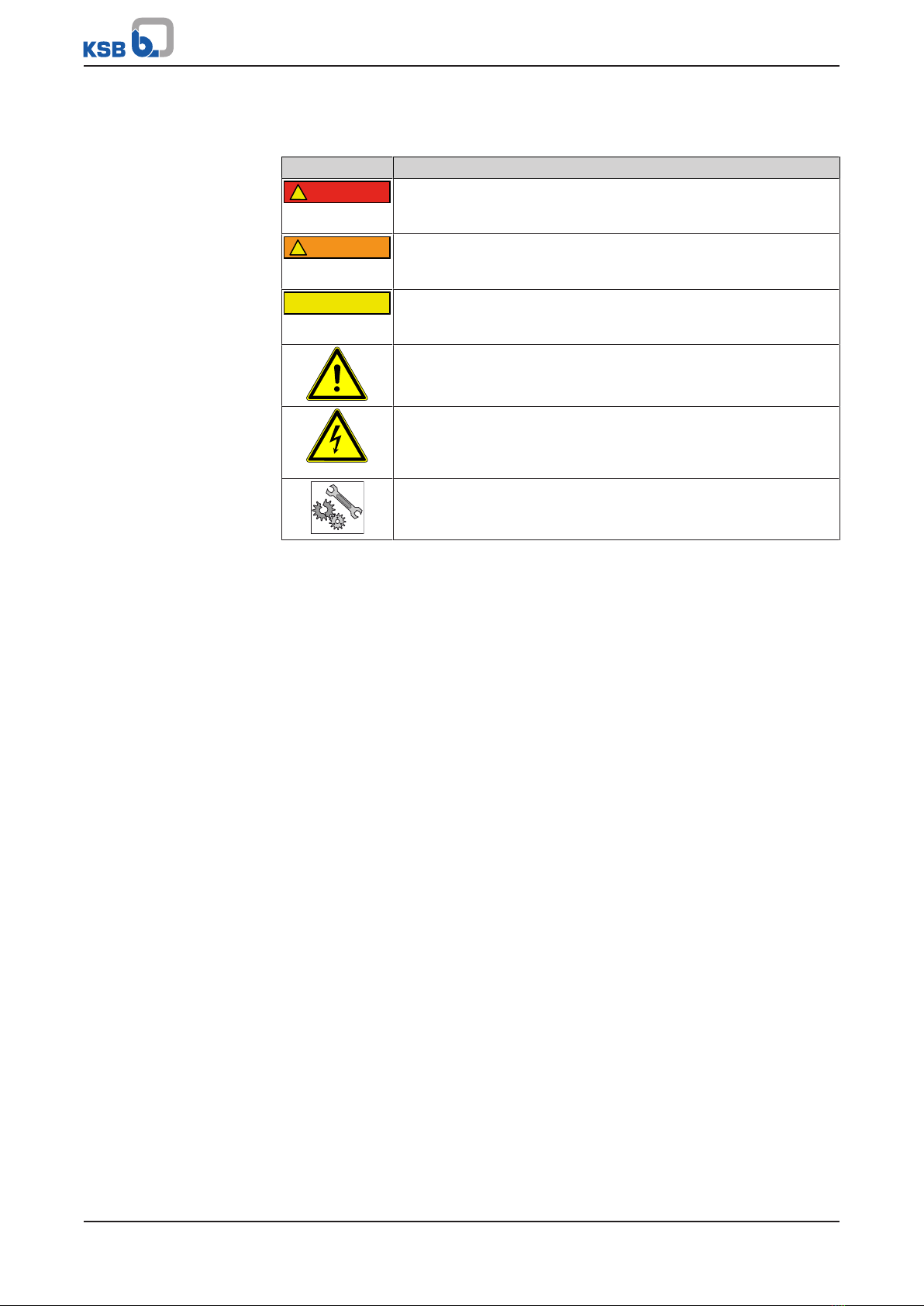
1.6 Key to safety symbols/markings.......................................................................................................................7
2 Safety...................................................................................................................................................... 8
2.1 General..............................................................................................................................................................8
2.2 Intended use .....................................................................................................................................................8
2.3 Personnel qualification and training...............................................................................................................9
2.4 Consequences and risks caused by non-compliance with this manual .........................................................9
2.5 Safety awareness ..............................................................................................................................................9
2.6 Safety instructions for the operator/user........................................................................................................9
2.7 Safety information for maintenance, inspection and installation ..............................................................10
2.8 Unauthorised modes of operation................................................................................................................10
3 Transport/Storage/Disposal ................................................................................................................ 11
3.1 Checking the condition upon delivery..........................................................................................................11
3.2 Transport.........................................................................................................................................................11
3.3 Storage/preservation......................................................................................................................................11
3.4 Return to supplier...........................................................................................................................................12
3.5 Disposal ...........................................................................................................................................................12
4 Description............................................................................................................................................ 13
4.1 General description ........................................................................................................................................13
4.2 Product information as per Regulation No. 1907/2006(REACH).................................................................13
4.3 Designation.....................................................................................................................................................14
4.4 Name plate......................................................................................................................................................14
4.5 Design details..................................................................................................................................................15
4.6 Configuration and function...........................................................................................................................16
4.7 Noise characteristics .......................................................................................................................................17
4.8 Scope of supply...............................................................................................................................................17
4.9 Dimensions and weights ................................................................................................................................18
4.10 Accessories ......................................................................................................................................................18
5 Installation at Site................................................................................................................................ 19
5.1 Safety regulations...........................................................................................................................................19
5.2 Checks to be carried out prior to installation...............................................................................................20
5.3 Mounting/installing the underfloor box.......................................................................................................21
5.3.1 Installing the underfloor box ........................................................................................................... 21
5.3.2 Underfloor box: Connecting the piping .......................................................................................... 23
5.3.3 Underfloor box: Fitting the level-adjusting piece/ puddle flange with level-adjusting piece (not
included in the scope of supply) ...................................................................................................... 28
5.3.4 Underfloor box: Backfilling around the collecting tank and pouring concrete around the top. 30
5.3.5 Underfloor box: Fitting the sealing collar ....................................................................................... 32
5.4 Installing the above-floor box .......................................................................................................................35
5.4.1 Installing the above-floor box.......................................................................................................... 35
5.4.2 Above-floor box: Connecting the piping......................................................................................... 36
5.5 Installing the pump set ..................................................................................................................................39
5.5.1 Single-pump lifting units: Installing the pump set ......................................................................... 39
5.5.2 Dual-pump lifting units: Installing the pump set............................................................................ 43
5.6 Electrical connection ......................................................................................................................................49
5.6.1 Underfloor box: Electrical connection ............................................................................................. 49

Contents
4 of 84 AmaDrainer Box
5.6.2 Above-floor box: Electrical connection............................................................................................ 50
5.7 Fitting the cover plate/ cover........................................................................................................................53
5.7.1 Underfloor box: Fitting the cover plate........................................................................................... 53
5.7.2 Above-floor box: Fitting the cover................................................................................................... 54
5.8 Venting device with activated carbon filter (accessory) ..............................................................................55
6 Commissioning/Start-up/Shutdown................................................................................................... 56
6.1 Commissioning/Start-up.................................................................................................................................56
6.1.1 Prerequisites for commissioning/start-up ........................................................................................ 56
6.1.2 Start-up.............................................................................................................................................. 56
6.2 Operating limits..............................................................................................................................................57
6.2.1 Free passage ...................................................................................................................................... 57
6.2.2 Fluid handled .................................................................................................................................... 58
6.3 Shutdown/storage/preservation ....................................................................................................................59
6.3.1 Measures to be taken for shutdown................................................................................................ 59
6.3.2 Stopping ............................................................................................................................................ 59
6.4 Returning to service .......................................................................................................................................59
7 Servicing/Maintenance........................................................................................................................ 60
7.1 Safety regulations...........................................................................................................................................60
7.2 Servicing/inspection........................................................................................................................................60
7.3 Drainage/cleaning ..........................................................................................................................................61
7.4 Recommended spare parts stock...................................................................................................................61
8 Trouble-shooting.................................................................................................................................. 62
9 Related Documents.............................................................................................................................. 63
9.1 Exploded view and list of components .........................................................................................................63
9.1.1 Single-pump lifting units: underfloor box/ above-floor box......................................................... 63
9.1.2 Dual-pump lifting units: underfloor box / above-floor box ........................................................... 68
9.2 Dimensions and connections .........................................................................................................................72
9.2.1 Underfloor box: Dimensions and connections ................................................................................ 72
9.2.2 Above-floor box: Dimensions and connections............................................................................... 74
9.3 Installation example.......................................................................................................................................76
9.3.1 Underfloor box: installation example.............................................................................................. 76
9.3.2 Above-floor box: Installation example ............................................................................................ 77
10 EU Declaration of Conformity............................................................................................................. 78
11 Declaration of Performance as per Regulation (EU) No. 305/2011, Annex III.................................. 79
12 Certificate of Decontamination........................................................................................................... 80
Index ..................................................................................................................................................... 81

Glossary
5 of 84
AmaDrainer Box
2336.81/12-EN
Glossary
Backflow loop
The section of the discharge pipe of a waste water
lifting unit that is located above the flood level
Certificate of decontamination
A certificate of decontamination is enclosed by the
customer when returning the product to the
manufacturer to certify that the product has been
properly drained to eliminate any environmental
and health hazards arising from components in
contact with the fluid handled.
Collecting tank
Component of a grey water lifting unit in which
the incoming grey water is stored in unpressurised
condition prior to automatic lifting.
Domestic grey water
Faecal-free waste water (grey water) from
washbasins, showers, washing machines, etc.
Grey water lifting unit
Device for collecting and automatically lifting
faecal-free waste water above the flood level
Nominal size DN
Identifier (inside diameter) used for characterising
mating components such as pipes, pipe
connections and fittings
Stormwater
Water from natural precipitation which has not
been contaminated by any form of use
Submersible motor pump
Submersible motor pumps are floodable, close-
coupled units which are not self-priming. The
pumps are usually operated completely
submerged. They may be operated outside the
fluid for short periods of time, until the minimum
fluid level has been reached.
Swing check valve
Element of a waste water lifting unit which
prevents waste water from flowing back from the
discharge line into the waste water lifting unit.

1 General
6 of 84 AmaDrainer Box
2336.81/12-EN
1 General
1.1 Principles
This operating manual is valid for the type series and variants indicated on the front
cover.
The operating manual describes the proper and safe use of this equipment in all
phases of operation.
The name plate indicates the type series, the main operating data and the serial
number. The serial number uniquely describes the product and is used as
identification in all further business processes.
In the event of damage, immediately contact your nearest KSB service facility to
maintain the right to claim under warranty.
1.2 Installation of partly completed machinery
To install partly completed machinery supplied by KSB refer to the sub-sections under
Servicing/Maintenance.
1.3 Target group
This operating manual is aimed at the target group of trained and qualified specialist
technical personnel. (ðSection2.3,Page9)
1.4 Other applicable documents
Table1: Overview of other applicable documents
Document Contents
Sub-supplier product literature Operating manuals and other product literature
describing accessories and integrated machine
parts,
submersible motor pump operating manual,
switchgear operating manual for dual-pump lift-
ing units
1.5 Symbols
Table2: Symbols used in this manual
Symbol Description
✓Conditions which need to be fulfilled before proceeding with the
step-by-step instructions
⊳Safety instructions
⇨Result of an action
⇨Cross-references
1.
2.
Step-by-step instructions
Note
Recommendations and important information on how to handle
the product

1 General
7 of 84
AmaDrainer Box
2336.81/12-EN
1.6 Key to safety symbols/markings
Table3: Definition of safety symbols/markings
Symbol Description
!DANGER
DANGER
This signal word indicates a high-risk hazard which, if not avoided,
will result in death or serious injury.
WARNING
!
WARNING
This signal word indicates a medium-risk hazard which, if not
avoided, could result in death or serious injury.
CAUTION
CAUTION
This signal word indicates a hazard which, if not avoided, could res-
ult in damage to the machine and its functions.
General hazard
In conjunction with one of the signal words this symbol indicates a
hazard which will or could result in death or serious injury.
Electrical hazard
In conjunction with one of the signal words this symbol indicates a
hazard involving electrical voltage and identifies information about
protection against electrical voltage.
Machine damage
In conjunction with the signal word CAUTION this symbol indicates
a hazard for the machine and its functions.

2 Safety
8 of 84 AmaDrainer Box
2336.81/12-EN
2 Safety
!DANGER
All the information contained in this section refers to hazardous situations.
In addition to the present general safety information the action-related safety
information given in the other sections must be observed.
2.1 General
▪This operating manual contains general installation, operating and maintenance
instructions that must be observed to ensure safe operation of the system and
prevent personal injury and damage to property.
▪Comply with all the safety instructions given in the individual sections of this
operating manual.
▪The operating manual must be read and understood by the responsible specialist
personnel/operators prior to installation and commissioning.
▪The contents of this operating manual must be available to the specialist
personnel at the site at all times.
▪Information and markings attached directly to the product must always be
complied with and kept in a perfectly legible condition at all times. This applies
to, for example:
– Arrow indicating the direction of rotation
– Markings for connections
– Name plate
▪The operator is responsible for ensuring compliance with all local regulations not
taken into account.
2.2 Intended use
▪The lifting unit must not be used in potentially explosive atmospheres.
▪The lifting unit must only be operated within the operating limits described in
the other applicable documents.
▪Only operate lifting units which are in perfect technical condition.
▪Do not operate partially assembled lifting units.
▪Only use the lifting unit to handle the fluids described in the product literature
of the respective design variant.
▪Never operate the lifting unit without the fluid to be handled
▪Observe the minimum flow rates indicated in the data sheet or product literature
(to prevent overheating, bearing damage, etc).
▪Observe the minimum flow rate and maximum flow rate indicated in the data
sheet or product literature (to prevent overheating, mechanical seal damage,
cavitation damage, bearing damage, etc).
▪Do not throttle the flow rate on the inlet side of the lifting unit (to prevent
cavitation damage)
▪Consult the manufacturer about any use or mode of operation not described in
the data sheet or product literature.
▪Never exceed the permissible application and operating limits specified in the
data sheet or product literature regarding pressure, temperature, etc.
▪Observe all safety information and instructions in this manual.

2 Safety
9 of 84
AmaDrainer Box
2336.81/12-EN
2.3 Personnel qualification and training
All personnel involved must be fully qualified to install, operate, maintain and
inspect the equipment this manual refers to.
The responsibilities, competence and supervision of all personnel involved in
installation, operation, maintenance and inspection must be clearly defined by the
operator.
Deficits in knowledge must be rectified by means of training and instruction
provided by sufficiently trained specialist personnel. If required, the operator can
commission the manufacturer/supplier to train the personnel.
Training on the lifting unit must always be supervised by technical specialist
personnel.
2.4 Consequences and risks caused by non-compliance with this manual
▪Non-compliance with these operating instructions will lead to forfeiture of
warranty cover and of any and all rights to claims for damages.
▪Non-compliance can, for example, have the following consequences:
– Hazards to persons due to electrical, thermal, mechanical and chemical
effects and explosions
– Failure of important product functions
– Failure of prescribed maintenance and servicing practices
– Hazard to the environment due to leakage of hazardous substances
2.5 Safety awareness
In addition to the safety information contained in this operating manual and the
intended use, the following safety regulations shall be complied with:
▪Accident prevention, health regulations and safety regulations
▪Explosion protection regulations
▪Safety regulations for handling hazardous substances
▪Applicable standards, directives and laws
2.6 Safety instructions for the operator/user
▪Fit protective equipment (e.g. contact guards) supplied by the operator for hot,
cold or moving parts, and check that the equipment functions properly.
▪Do not remove any protective equipment (e.g. contact guards) during operation.
▪Provide the personnel with protective equipment and make sure it is used.
▪Contain leakages (e.g. at the shaft seal) of hazardous fluids handled (e.g.
explosive, toxic, hot) so as to avoid any danger to persons and the environment.
Adhere to all relevant laws.
▪Eliminate all electrical hazards. (In this respect refer to the applicable national
safety regulations and/or regulations issued by the local energy supply
companies.)

2 Safety
10 of 84 AmaDrainer Box
2336.81/12-EN
2.7 Safety information for maintenance, inspection and installation
▪Modifications or alterations of the lifting unit require the manufacturer's prior
consent.
▪Use only original spare parts or parts authorised by the manufacturer. The use of
other parts can invalidate any liability of the manufacturer for resulting damage.
▪The operator ensures that maintenance, inspection and installation are
performed by authorised, qualified specialist personnel who are thoroughly
familiar with the manual.
▪Carry out work on the lifting unit during standstill only.
▪The pump casing must have cooled down to ambient temperature.
▪Pump pressure must have been released and the pump must have been drained.
▪When taking the lifting unit out of service always adhere to the procedure
described in the manual.
▪Decontaminate lifting units which handle fluids posing a health hazard.
▪As soon as the work has been completed, re-install and re-activate any safety-
relevant devices and protective devices. Before returning the product to service,
observe all instructions on commissioning.
▪Make sure the lifting unit cannot be accessed by unauthorised persons (e.g.
children).
2.8 Unauthorised modes of operation
Always observe the limits stated in the product literature.
The warranty relating to the operating reliability and safety of the lifting unit
supplied is only valid if the equipment is used in accordance with its intended use.
(ðSection2.2,Page8)

3 Transport/Storage/Disposal
11 of 84
AmaDrainer Box
2336.81/12-EN
3 Transport/Storage/Disposal
3.1 Checking the condition upon delivery
1. On transfer of goods, check each packaging unit for damage.
2. In the event of in-transit damage, assess the exact damage, document it and
notify KSB or the supplying dealer and the insurer about the damage in writing
immediately.
3.2 Transport
DANGER
The grey water lifting unit could slip out of the suspension arrangement
Danger to life from falling parts!
▷Observe the weights indicated.
▷Observe the applicable local accident prevention regulations.
▷Use suitable, approved lifting accessories.
DANGER
Grey water lifting unit falling off the pallet
Risk of injury by falling grey water lifting unit!
▷Always transport the grey water lifting unit in horizontal position.
▷Give due attention to the weight data and the centre of gravity.
▷Never suspend the pump by its power cable.
▷Prevent the grey water lifting unit from getting knocked or dropped.
3.3 Storage/preservation
CAUTION
Damage during storage due to frost, humidity, dirt, UV radiation or vermin
Corrosion/contamination of the lifting unit!
▷Store the lifting unit in a frost-proof, roofed area.
CAUTION
Wet, contaminated or damaged openings and connections
Leakage or damage of the grey water lifting unit!
▷Only open the openings of the grey water lifting unit at the time of
installation.
If commissioning is to take place some time after delivery, we recommend that the
following measures be taken:
Store the grey water lifting unit in a dry, protected room where the atmospheric
humidity is as constant as possible.

3 Transport/Storage/Disposal
12 of 84 AmaDrainer Box
2336.81/12-EN
3.4 Return to supplier
1. Drain the lifting unit as described in the manual.
2. Always flush and clean the lifting unit, particularly if it has been used for
handling noxious, explosive, hot or other hazardous fluids.
3. If the unit has handled fluids whose residues could lead to corrosion damage in
the presence of atmospheric humidity or could ignite upon contact with oxygen,
the unit must also be neutralised and blown through with anhydrous inert gas
to ensure drying.
4. Always complete and enclose a certificate of decontamination when returning
the lifting unit. (ðSection12,Page80)
Always indicate any safety and decontamination measures taken.
NOTE
If required, a blank certificate of decontamination can be downloaded from the
following web site: www.ksb.com/certificate_of_decontamination
3.5 Disposal
WARNING
Fluids handled, consumables and supplies which are hot and/or pose a health
hazard
Hazard to persons and the environment!
▷Collect and properly dispose of flushing fluid and any fluid residues.
▷Wear safety clothing and a protective mask if required.
▷Observe all legal regulations on the disposal of fluids posing a health hazard.
1. Dismantle the lifting unit.
Collect greases and other lubricants during dismantling.
2. Separate and sort the pump materials, e.g. by:
- Metals
- Plastics
- Electronic waste
- Greases and other lubricants
3. Dispose of materials in accordance with local regulations or in another
controlled manner.

4 Description
13 of 84
AmaDrainer Box
2336.81/12-EN
4 Description
4.1 General description
▪Automatic grey water lifting unit
▪Lifting unit for collecting unpressurised, domestic waste water without faeces as
well as stormwater and automatically lifting it above the flood level.
Material variant A (standard variant)
▪Chemically neutral grey water
▪Slightly contaminated grey water (≤ 40°C)
▪Wash water (up to 90 °C max. for short periods t ≤ 3minutes)
Material variant C (for aggressive fluids)
In addition to standard variant:
▪Swimming pool water1)
▪Brackish water
▪Seawater
▪Water containing salt
▪Aggressive fluids
▪Condensate from heat recovery applications
Variant R (for fluids handled containing oil/ oil emulsions)
In addition to standard variant:
▪Oil emulsions and cutting oils
▪Grey water containing oil
4.2 Product information as per Regulation No. 1907/2006(REACH)
For information as per European chemicals regulation (EC) No. 1907/2006 (REACH)
see https://www.ksb.com/en-global/company/corporate-responsibility/reach.
1Swimming pool water (0.4 to 1.4mg/l free chlorine, combined chlorine ≤0.6mg/l, pH6.9 to 7.7, water hardness
10 to 30°dH, salt content ≤7g/l)

4 Description
14 of 84 AmaDrainer Box
2336.81/12-EN
4.3 Designation
Example: AmaDrainer Box Z2.1 U 301
Table4: Designation key
Code Description
AmaDrainer Box Type series
Z Design
-2) Single-pump lifting unit
Z Dual-pump lifting unit
2 Collecting tank volume
1 100l
2 200l
.1 Version
.1 Version .1
U Installation type
B Above-floor installation
U Underfloor installation
301 Pump set
301 AmaDrainer 301
4.4 Name plate
2
1
3
4
5
EN 12 050-2
0197 11
DoP2336.1-01
FO001996 Made in Germany
A2022w27
AmaDrainer Box Z2 B
Johann-Klein-Straße 9
Deutschland
67227 Frankenthal
KSB SE & Co. KGaA
Fig.1: Name plate (example)
1 Type series, size 4 Reference number of the declaration
of performance
2 Principles of construction and testing 5 Production year and production
week
3 Notified body, year of introduction
2Blank

4 Description
15 of 84
AmaDrainer Box
2336.81/12-EN
4.5 Design details
Design
▪Single-pump unit or dual-pump unit
▪1 or 2 submersible motor pumps
▪Fill level measurement via float switch
▪Nominal tank volume 100l or 200l
▪Collecting tank made of impact-resistant plastic
▪Piping
▪Integrated swing check valve
▪To EN 12050-2
▪Level-adjusting extension, cover plate with floor drain and siphon trap
(underfloor box)
▪Closed by odour-proof cover and locking ring (above-floor box)
Installation
▪Installation in substructures or foundations (underfloor box)
▪Floor mounting (above-floor box)
Drive
▪AC motor
▪Three-phase motor
▪Integrated temperature switches
Impeller type
▪Open multi-vane impeller, free passage 10mm or 11mm
▪Vortex impeller, free passage 18mm or 35mm
Connections
▪Inlet side DN50 / DN70 / DN100 (single-pump lifting unit)
▪Inlet side DN50 / DN70 / DN100 / DN150 (dual-pump lifting unit)
▪Discharge outlet DN50/ G 2

4 Description
16 of 84 AmaDrainer Box
2336.81/12-EN
4.6 Configuration and function
1
2
3
4
5
Fig.2: Illustration of the grey water lifting unit (example)
1 Collecting tank 4 Discharge line connection
2 Inlet line connection 5 Submersible motor pump incl. float
switch
3 Swing check valve
Design The grey water lifting unit consists of a stable collecting tank (1) with integrated
submersible motor pump and float switch (5), inlet line connection (2), swing check
valve (3) and discharge line connection (4).
Function The fluid to be handled flows into the grey water lifting unit through an inlet line
connection (2) and is collected in an odour-tight and water-tight collecting tank (1).
When a specific fluid level is reached, the float switch triggers the automatic start of
the submersible motor pump (5). The fluid handled is pumped through the discharge
line connection (4) to a level above the flood level and discharged into the public
sewer.

4 Description
17 of 84
AmaDrainer Box
2336.81/12-EN
4.7 Noise characteristics
Sound pressure level < 70 dB(A)
4.8 Scope of supply
The off-the-shelf range contains the complete grey water lifting unit as one material
number.
The configurable range serves to individually select the components composing the
grey water lifting unit.
In either case, the grey water lifting unit is supplied in several parts for assembly on
site. The grey water lifting unit meets the requirements of EN12050-2.
Underfloor box 1.1U - single-pump unit
▪Collecting tank made of impact-resistant plastic, 100litres, for installation in
substructures or foundations. Cover with level-adjusting extension, cover plate
with floor drain and siphon trap.
Supplied in three parts:
▪Collecting tank with extension, cover plate ClassK3
▪Submersible grey water pump that starts and stops automatically, with 10m
power cable, shockproof plug or CEE plug3)
▪Connection set with full set of installation parts, swing check valve4)
Underfloor Box Z2.1 U – dual-pump unit
▪Collecting tank made of impact-resistant plastic, 200litres, for installation in
substructures and foundations. Cover with level-adjusting extension, cover plate
with floor drain and siphon trap.
Supplied in four parts:
▪Collecting tank with extension, cover plate ClassK3
▪Two submersible grey water pumps with 10m power cable, shockproof plug or
free cable end (for models with three-phase motor).
▪Connection set with full set of installation parts, swing check valve5), two float
switches, with 10m electric cable
▪LevelControl Basic2 control unit for dual-pump units with automatic pump
changeover function, peak-load operation function, stand-by function
Above-floor box 1.1 B – single-pump unit
▪Collecting tank made of impact-resistant plastic, 100litres, for floor mounting;
closed with odour-proof cover and locking ring
Supplied in three parts:
▪Collecting tank with cover, locking ring
▪Submersible grey water pump that starts and stops automatically, with 10m
power cable, shockproof plug or CEE plug6)
▪Connection set with full set of installation parts, swing check valve7)
Above-floor box Z2.1 B – dual-pump unit
▪Collecting tank made of impact-resistant plastic, 200litres, for floor mounting;
closed with odour-proof, screw-on cover
3For models with three-phase motor
4AmaDrainer 301, 303 and 322 with integrated swing check valve
5AmaDrainer 301, 303 and 322 with integrated swing check valve
6For models with three-phase motor
7AmaDrainer 301, 303 and 322 with integrated swing check valve

4 Description
18 of 84 AmaDrainer Box
2336.81/12-EN
Supplied in four parts:
▪Collecting tank with cover, locking ring
▪Two submersible grey water pumps with 10m power cable, shockproof plug or
free cable end (for models with three-phase motor).
▪Connection set with full set of installation parts, swing check valve8), two float
switches, with 10m electric cable
▪LevelControl Basic2 control unit for dual-pump units with automatic pump
changeover function, peak-load operation function, stand-by function
4.9 Dimensions and weights
For dimensions refer to the outline drawing of the grey water lifting unit.
Table5: Weights of the lifting units and collecting tanks (off-the-shelf range)
Characteristic Single-pump unit Dual-pump unit
Underfloor box Above-floor box Underfloor box Above-floor box
[kg] [kg] [kg] [kg]
Total weight 20 to 30 13 to 23 50 to 68 47 to 66
Weight of the col-
lecting tank
15,7 8,7 31,3 28,9
4.10 Accessories
Depending on the design variant, the following parts may be included with the
delivery:
▪Pipe adapters for connecting inlet lines and vent lines of different diameters
▪Socket gate valve
▪Venting device with activated carbon filter
▪Sealing collar for connecting a site-supplied sealing sheet (underfloor box only)
▪Puddle flange for protection against water exerting a constant hydrostatic
pressure (underfloor box only)
▪Level-adjusting piece H = 300mm (for underfloor box as dual-pump lifting unit
only)
▪M1 alarm contact9)
▪KSB washing machine interrupter10)
8AmaDrainer 301, 303 and 322 with integrated swing check valve
9In combination with one of the alarm switchgears (AS0, AS2, AS4 or AS5) the M1 alarm contact triggers an
alarm if the permissible fluid level in the collecting tank is exceeded. Only for AmaDrainer Box (100 l).
10 The KSB washing machine interrupter triggers an alarm and stops the washing machine before the collecting
tank overflows.

5 Installation at Site
19 of 84
AmaDrainer Box
2336.81/12-EN
5 Installation at Site
NOTE
All lifting units are supplied unassembled in the form of subassemblies. The
following sections describe the conditions which must be met to assemble the
individual subassemblies to form the complete grey water lifting unit in accordance
with the instructions and without compromising health and safety.
5.1 Safety regulations
DANGER
Power supply not disconnected
Danger to life!
▷Pull the mains plug and secure the pump against unintentional start-up.
DANGER
Electrical connection work by unqualified personnel
Danger of death from electric shock!
▷Always have the electrical connections installed by a trained and qualified
electrician.
▷Observe regulations IEC 60364 .
DANGER
Unsuitable electrical installation
Danger to life!
▷The electrical installation has to meet the VDE 0100 installation rules (sockets
with earthing terminals)
▷Make sure the electric mains is equipped with a residual current device with a
maximum residual current rating of 30mA.
▷Always have the electrical connections installed by a trained electrician.
DANGER
Improper use
Danger of death from electric shock!
▷Any extension cords must match the quality of the power cable supplied with
the pump.
▷Do not expose electrical connections or devices to moisture.
NOTE
If the supply of mains voltage is interrupted or the submersible motor pump is
defective, there is a risk of flooding damage. Prevent damage by using a mains-
independent alarm switchgear or a KSB washing machine interrupter.

5 Installation at Site
20 of 84 AmaDrainer Box
2336.81/12-EN
5.2 Checks to be carried out prior to installation
NOTE
Observe the provisions of EN 12056 (Gravity Drainage Systems in Buildings) when
installing the unit at site.
NOTE
For lifting units in an odour-proof enclosure vent the lifting unit via the roof.
NOTE
If transport locks have been fitted, remove them prior to the installation.
NOTE
Do not operate lifting units near living quarters and sleeping quarters.
Before beginning with the installation check the following:
▪The data on the name plate of the grey water lifting unit have been checked.
The grey water lifting unit must be suitable for operation on the available power
supply network. (ðSection4.4,Page14)
▪The power of the pump set used is suitable for the operating conditions and the
hydraulic losses in the discharge line.
▪The fluid handled is a permissible fluid. (ðSection6.2.2.1,Page58)
▪All safety information has been complied with.
▪The place of installation is frost-proof.
Table of contents
Other KSB Industrial Equipment manuals

KSB
KSB 9972073510/200 Manual

KSB
KSB LevelControl Basic 2 User manual

KSB
KSB 4K Series Installation instructions

KSB
KSB Amarex N Manual

KSB
KSB 88980/41 Manual

KSB
KSB GIW MDX Installation instructions

KSB
KSB Amarex N Manual

KSB
KSB Amarex KRT Manual

KSB
KSB 4EYS Installation instructions

KSB
KSB BOAX-S User manual
Popular Industrial Equipment manuals by other brands

Balluff
Balluff BTL PA0400 Series user guide

Blohm + Voss Oil Tools
Blohm + Voss Oil Tools FloorHand 9GF-1102 Technical documentation

Schwarz
Schwarz SB10B operating instructions

Festo
Festo MPS Station manual

NetterVibration
NetterVibration NWE Series operating instructions

Marshall Excelsior
Marshall Excelsior Accu-Max+ Series Installation information