Novexx Solutions EIDDOS XTOXLnie User manual

User Manual XTOXLnie/ XTOXLnce
Edition A - 01/2024
Original Instructions - keep for future reference
RT823
USER MANUAL
XTOXL4ie / XTOXL5ie / XTOXL6ie
XTOXL4ce / XTOXL5ce / XTOXL6ce
LH-RH versions
Thermal Transfer Overprinter (TTO) for large areas,
configurable for intermittent or continuous operation
This manual contains the EC Declaration of Conformity


User Manual XTOXLnie/ XTOXLnce
Edition A- 01/2024
1
Contents
Contents
Information................................................................................................................................2
NOTES ON THE CORRECT USE OF THE PRINTER ..............................................................................2
GENERAL NOTES...............................................................................................................................2
SAFETY NOTICES...............................................................................................................................3
GENERAL PRECAUTIONS ..................................................................................................................3
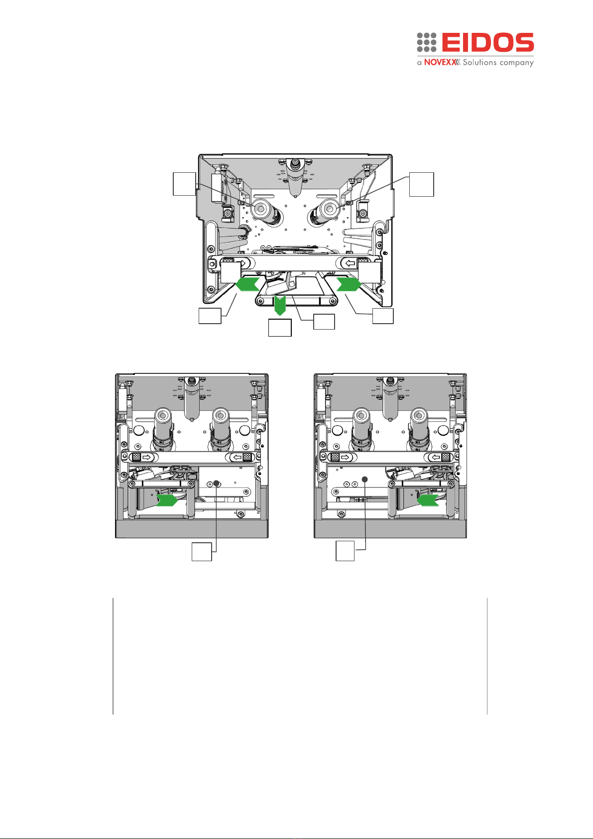
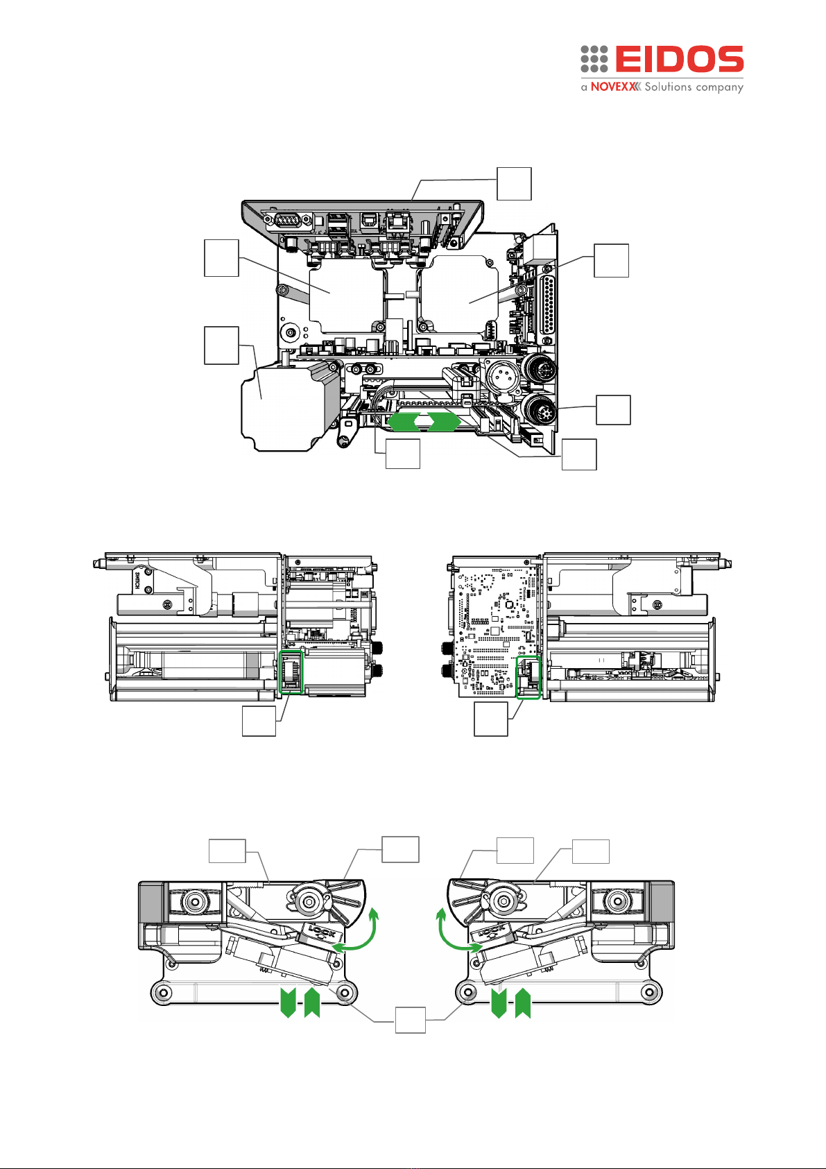
DANGEROUS AREAS ON THE PRINTING UNIT..................................................................................4
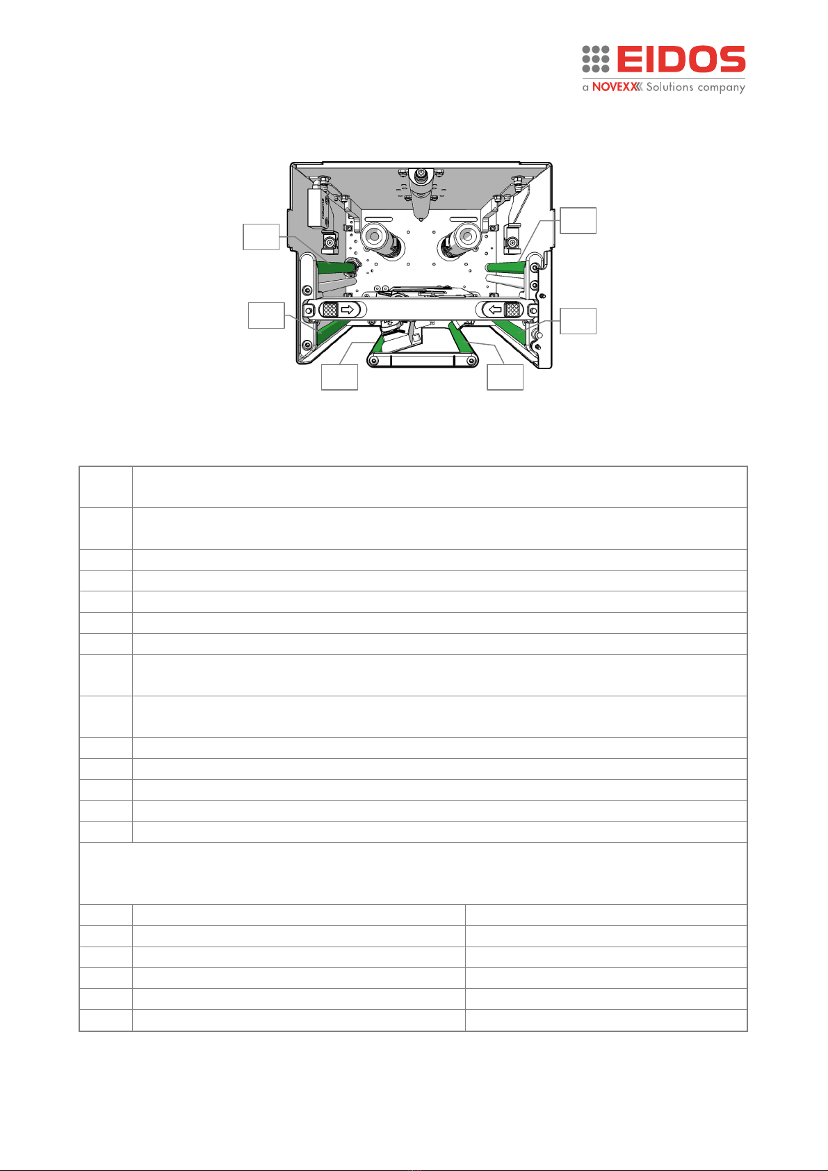
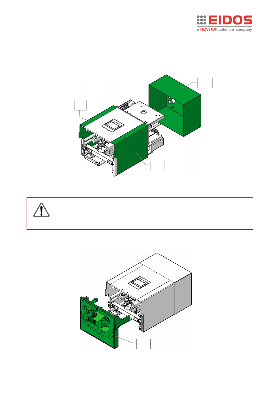
PROTECTION ELEMENTS PROVIDED ................................................................................................7
Product Description .................................................................................................................11
FUNCTIONALITY .............................................................................................................................11
PECULIARITY ...................................................................................................................................11
CARRIAGE STROKE LENGTHS AND MACHINE TYPE........................................................................12
SYSTEM CONFIGURATIONS ............................................................................................................13
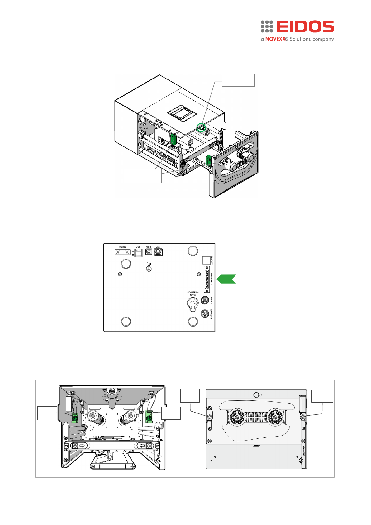
REAR CONNECTION PANEL ............................................................................................................16
OPERATING PANEL.........................................................................................................................17
BASIC SETTINGS..............................................................................................................................20
Operation ................................................................................................................................26
INSERTING CONSUMABLES ............................................................................................................26
THE THERMAL RIBBONS.................................................................................................................27
PRINTING........................................................................................................................................28
CREATION AND SENDING OF THE LABEL WITH EASYCODE ...........................................................29
HOW TO STORE LABEL FILES (.LM1)...............................................................................................31
HOW TO BACK UP ..........................................................................................................................31
SETTING AND MONITORING ..........................................................................................................32
STATUS MESSAGES.........................................................................................................................57
Preventive Maintenance ..........................................................................................................59
CLEANING INSTRUCTIONS..............................................................................................................59
CLEANING THE PRINT HEAD...........................................................................................................60
CLEANING THE CARRIAGE SLIDING GUIDE.....................................................................................60
CLEANING THE PRINTING PLATE (XTOXL Intermittent) .................................................................61
CLEANING THE PRINTING ROLLER (XTOXL Continuous) ................................................................61
CLEANING ROLLS AND RIBBON PASSAGES ....................................................................................62
Appendix 1...............................................................................................................................63
EC DECLARATION OF CONFORMITY...............................................................................................63
Appendix 2...............................................................................................................................64
CE LABEL.........................................................................................................................................64
Appendix 3...............................................................................................................................65
ZEBRA and EIDOS NICELABEL EMULATION FILE MANAGEMENT (.prn, .zpl) .................................65

User Manual XTOXLnie/ XTOXLnce
Edition A - 01/2024
2
Information
Information
NOTES ON THE CORRECT USE OF THE PRINTER
Read these notes together with Chapter “Safety notices" to ensure that the printer is used correctly.
Switching on the printer.
•If the printer has been left in a cold or excessively hot environment for a considerable time, wait
at least 1 hour before switching it on to prevent humidity collecting on the internal circuits.
•After switching off, wait for a few seconds before switching on the printer again.
Use in particularly places
If the printer is going to be used in particularly humid conditions (for example cheese factories) the
protection kits are necessary. Do not use it where there is a lot of oil, iron particles, or dust.
Disposal
The device may not be disposed of with household rubbish. This appliance is labelled in
accordance with European Directive 2012/19/UE concerning used electrical and
electronic appliances (waste electrical and electronic equipment - WEEE).
The guideline determines the framework for the return and recycling of used appliances
as applicable throughout the EU. To return your used device, please use the return and
collection systems available to you.
GENERAL NOTES
Validity of this manual and required compliance
This user manual refers exclusively to the electronic printer for thermal transfer to film named XTO.
It is used for proper operation and adjustment of the printer.
The printer must be properly installed and configured to allow for operation and settings.
For information about installation and maintenance, see the Installation manual.
For technical questions not covered in this operating manual request a service technician.
Technical release
Software version: 2.9
Hardware version: 68XTOXL10A-LH, 68XTOXL10B-RH
These instructions have to be kept for future reference and must be
available throughout the expected life of the product.
Liability and Copyright
All rights to this manual are reserved. This manual may not be reproduced in any form, either wholly
or partially, without the express written authorisation of Eidos Srl. The contents of this manual are
subject to modifications and improvements without prior warning. Every effort has been made to
ensure the accuracy of the contents. If errors and/or inaccuracies are detected, inform Eidos Srl in
order to make the manual as exhaustive as possible. Eidos Srl accepts no responsibility for any
accidental errors or for any damage arising from the supply, scope or use of this manual.

User Manual XTOXLnie/ XTOXLnce
Edition A - 01/2024
3
Information
How information is represented
Explanation of symbols
WARNING!
A warning symbol refers to risks that can result in severe or fatal injuries! The text
within this area contains instructions for preventing damage.
➔Instructions must be followed without exception.
WARNING! The text within this area contains important recommendations as well as additional
information or information to use the product correctly and efficiently.
SAFETY NOTICES
The printer is provided with a “EC Declaration of conformity” according to the "Machinery Directive
2006/42/EC" which includes the reference standards for "Electromagnetic Compatibility" and
"Electrical Safety":
1.
Do not start up the machine without first reading and implementing the prescriptions of the
“USER MANUAL” and the present “SAFETY NOTICES”.
2.
The printing unit is equipped with a removable front cover [RM1] for changing the thermal
ribbon, monitored by sensors [SENS_C1] and [SENS4] which switch off the power supply to
the motors when the cover is open.
3.
The printer must not be used in an explosive environment or be used to treat explosive
materials.
4.
The printer must not be used in irregular situations such as working without guards being
correctly fitted to the machine; working with products other than those prescribed.
5.
After 7 years of operation on an 8-hour daily shift, a complete overhaul of the product is
recommended.
GENERAL PRECAUTIONS
1.
Be careful when moving or carrying the printer. Wear safety shoes when installing or removing
the printer from the packaging machine: dropping the printer may cause injury or property
damage. The machine must NOT be used by the lid or the handle (See the "LIFTING AND
TRANSPORT" Chapter of the Technical Manual RT824).
2.
Do not open the printer during printing.
3.
When cleaning the surface of the printer case, do not use the cloth that is soaked in thinner,
trichloroethylene, benzine, ketone or similar chemicals.
4.
Do not spill liquids or spray insecticide on the printer.
5.
When printer trouble occurs, do not try to dissemble it. Instead, consult our service personnel.

User Manual XTOXLnie/ XTOXLnce
Edition A - 01/2024
4
Information
DANGEROUS AREAS ON THE PRINTING UNIT
Dangerous areas - front and bottom view
Note:
if in intermittent mode, during the installation it is necessary to fix the
printing plate and the printing unit so that the plate prevents finger access
to the areas [A] and [B] where the carriage with the print head moves.
if in continuous mode, the zones [A] and [B] are potentially dangerous zones
during the movement of the carriage to search for the position of the
printing roller, which occurs exclusively at the start and after the release of
an anomaly. The carriage does not move during the normal print cycle.
Figure 1: dangerous areas - front view (RH version shown)
Figure 2: dangerous areas – bottom view (RH version shown)
s2
s1
S
H
T
t
X
Y
A
B

User Manual XTOXLnie/ XTOXLnce
Edition A - 01/2024
5
Information
Dangerous areas - rear view
Dangerous areas on - side views
Dangerous areas - carriage.
Figure 3: Dangerous areas - rear view
Figure 4: Dangerous areas - side views
Figure 5: Dangerous areas - carriage
M2
M3
M1
Y
U
P
X
W
P
Ct
Ct
Sm
t
LH
RH
Sm

User Manual XTOXLnie/ XTOXLnce
Edition A - 01/2024
6
Information
Passive (non-motorized) rotating rollers
Definitions
H
Movement of the carriage during printing or positioning in the "Service" area.
Danger of crushing the fingers
S
Movement of the carriage when returning to Home after printing or during a return from
"Service". Danger of crushing the fingers.
A
Access from the lower right side: carriage moving to the right (home position return)
B
Access from the lower left side: carriage moving to the left (print)
T
Movement of the print head
s1
Rotation of the mandrel holding the ribbon release coil
s2
Rotation of the mandrel holding the ribbon rewinding coil
X
Movement of the carriage during printing or positioning in the "Service" area.
Danger of crushing the fingers.
Y
Movement of the carriage when returning to Home after printing or during a return from
"Service". Danger of crushing the fingers.
P
Rotation movement of the pulley and the belt for transmitting motion to the carriage
W
Rotation movement of the pulley and the belt for transmitting motion to the carriage
Ct
Print head movement servomotor cam
R1
Rubberized ribbon encoder roller
R2…6
Free rollers for ribbon guide
Hot parts highlight on XTO:
Part temperatures were measured at ambient temperatures of 20 ° C and after the XTO ran at
full cadence for 7 hours.
M1
Ribbon unwinding motor body
T max. 45°C
M2
Ribbon rewinding motor body
T max. 50°C
M3
Carriage movement motor body
T max. 60°C
U
CPU Heatsink
T max. 50°C
t
Print head
T max. 60°C
sm
Print head motion servo motor body
T max. 55°C
Figure 6: free rollers
R1
R2
R3
R6
R4
R5

User Manual XTOXLnie/ XTOXLnce
Edition A - 01/2024
7
Information
PROTECTION ELEMENTS PROVIDED
Covers fixed with screws
WARNING!
Disconnect the 48Vdc power supply to the printer before removing the fixed guards
[RF1], [RF2],
[RF3]. The fixed guards must be removed only for extraordinary
maintenance or repairs.
Movable interlocked guard [RM1]
Figure 7: fixed cover
Figure 8: movable interlocked guard
RM1
RF2
RF1
RF3

User Manual XTOXLnie/ XTOXLnce
Edition A - 01/2024
8
Information
Monitoring sensors movable guard [RM1] inserted
External safety contacts: SAFETY_A and SAFETY_B (SAF_EXT)
NOTE: If not used, they must be jumpered.
Magnets and magnets ring
To ensure good fastening of the movable guard [RM1] to the printing unit, magnets [mg1], [mg2]
have been provided on the printer body and magnetic rings [am1], [am2] on the ribbon inserter.
Figure 9: monitoring sensors
SENS_C1
Magnetic sensor
SENS4
Figure 10: safety contacts
Figure 11: magnets
[SAF_EXT]
SAFETY_A
SAFETY_B
SAFETY_SAF
mg2
am2
mg1
am1

User Manual XTOXLnie/ XTOXLnce
Edition A - 01/2024
9
Information
Fixed guard but not solidly screwed to the Printing Unit (only for intermittent mode)
The Printing Plate [PP] cannot be strongly screwed to the Printing Unit [PU] because it is necessary
to leave the passage to the packaging film [PF] to be printed.
Note:
During the installation it is necessary to fix the printing plate [PP] and the
printing unit [PU] so that the plate prevents finger access to the areas [A]
and [B] (Figure 2) where the carriage with the print head moves.
On supports where there is an independent adjustment of the Printing Unit [PU] and the Printing
Plate [PP], it is always necessary to maintain a relative position between the two parts that prevents
access to dangerous areas. Also, to obtain a good print quality, the print head must be positioned
at a distance from the edge of the rubber layer, not less than 5 mm and that the Printing Plate [PP]
is always centred with respect to the Printing Unit [PU].
Figure 12: Printing plate
Figure 13: Printing plate and Print Unit position
[PU]
[PF]
[PP]
5mm
5mm

User Manual XTOXLnie/ XTOXLnce
Edition A - 01/2024
10
Information
Warning symbols on the machine
CAUTION!
Warning symbols on the machine provide important information for the
operating personnel.
➔Do not remove warning symbols.
➔Replace missing or illegible warning symbols.
Meaning of the warning symbols:
Warning symbol
Meaning
The "Hot surface" symbol informs the operator and the staff assigned to
the maintenance of the presence of potentially dangerous hot surfaces.
Allow the device to cool off before touching it.
Figure 14: printing plate alignment

User Manual XTOXLnie/ XTOXLnce
Edition A - 01/2024
11
Product DESCRIPTION
Product Description
FUNCTIONALITY
The XTO XL series is an electronic printer for "thermal transfer to film" that is able to write
automatically and directly on the plastic or paper film used in packaging machines by means of an
inked thermal ribbon.
The XTOXLnie “intermittent” codes the different production batches with variable text, barcodes
and logos extremely flexibly, ensuring high quality and fast printing.
The packaging film must be stationary during printing.
XTOXLnce “continuous” prints synchronously with the speed of the packaging machine. Since the
movement speed of the film is not constant, it is necessary to mount the "encoder" device on the
printing roller which allows the synchronism between the printing speed and the speed of the
packaging film.
In stand-alone operation, the label files created with the EASYCODE program installed in a PC can
be loaded in the printer using the USB memory key.
PECULIARITY
•Interchangeable 4"/5"/6" printheads
•Quick and intuitive printhead change
•Does not use compressed air.
•Easy to service and repair; easy system of ribbon passage for changing operation.
•Programmable printing steps and format printing parameters loadable by the touch screen
display (optional) or the P.C. through the use of a browser (Chrome, Edge ...).
•Improve unit uptime: not necessary to uninstall the print unit from the line.
•Modular assembly: mechanic + electronic.
•Easy and fast replacement of electronic components (no interference with mechanical parts).
•HMI (Human-Machine Interface) user friendly.
•Simply ribbon changing operation.
•Simply print plate cleaning and replacing directly on board the printer.
•Printer management (parameters, labels, diagnostic etc..) with local EIDOS Touch panel or
remote PC with a Web Browser.
TECHNICAL FEATURES
•"Corner edge" print head with 12 dots/mm definition (300 DPI).
•Max speed printing on continuous model: 500 mm/s (feasibility check necessary).
•Max speed printing on intermittent model: 600 mm/s (feasibility check necessary).
•Power supply required: 48Vdc - 320W.
•Incorporated and optimized "Ribbon saving" function.
•Moving of the ribbon and the head carriage by means of two "step" motors.

User Manual XTOXLnie/ XTOXLnce
Edition A - 01/2024
12
Product DESCRIPTION
CARRIAGE STROKE LENGTHS AND MACHINE TYPE
Models
Max. Print Area
intermittent
XTOXL4.ie
107 x 100 mm
XTOXL5.ie
128 x 100 mm
XTOXL6.ie
160 x 100 mm
continuous
XTOXL4.ce
107 x 990 mm
XTOXL5.ce
128 x 990 mm
XTOXL6.ce
160 x 990 mm
The printer can be supplied in 2 versions.
RIGHT HAND configuration: printing occurs when the carriage moves from left (home position) to
right.
LEFT HAND configuration: printing occurs when the carriage moves from right (home position) to
left.
The choice of configuration depends on the assembly on the production line.
The “XTOXL model” is shown on the red bar of the Help page.
Figure 15: printer model

User Manual XTOXLnie/ XTOXLnce
Edition A - 01/2024
13
Product DESCRIPTION
SYSTEM CONFIGURATIONS
WARNING!* the 45CV914/1 cable is supplied 7 meters long, but during installation
it must be cut as short as possible, to avoid the error signalling (E207) when closing
the front cover. The cable must pass far from the cables that supply motors or electro
valves, to avoid noises and spikes.
Note: The I/O SIGNALS Junction Box 49KS0162 is not intended for Industrial use.
Figure 16: system models
(capacitor kit to be connected
on the 48Vdc power supply
V+/V- output pins)
2 m
2 m
n = 4, 5 or 6 (printhead type)
nn = LH or RH
45CV932/1 + CE300434
XTOXL
49KS0162
+
XTOXL
49KS0162
+
XTOXL
49KS0162
+
XTOXL
49KS0162
+
7XTOXLnienn-2 /7XTOXLncenn-2
7XTOXLnienn-1 /7XTOXLncenn-1
7XTOXLnienn-3 /7XTOXLncenn-3
7XTOXLnienn-4 /7XTOXLncenn-4
45CV910/1
(capacitor kit to be connected
on the 48Vdc power supply
V+/V- output pins)
45CV910/1
45CV914/1
+48Vdc 320W
L = 7 m*
45CV914/1
+48Vdc 320W
L = 7 m*
2 m
2 m

User Manual XTOXLnie/ XTOXLnce
Edition A - 01/2024
14
Product DESCRIPTION
IP Version: 7XTOXLnienn-1TR / 7XTOXLnienn-1IP
7XTOXLncenn-1TR / 7XTOXLncenn-1IP
The TR printer version offers an IP30 protection degree, having electronic boards and print head
tropicalized. An IP printer version is available, with IP33 protection degree. It is equipped with
tropicalized electronic boards and print head, as well as a rear cover with adequate protection for
the connectors.
The optional 53SDK20 touch panel offers IP55 protection. An IP version of the Touch Panel, code
53SDK21, is also available, to be installed on the electrical cabinet of the packaging machine (a hole
is required).
Figure 17: TR/IP model
Figure 18: IP protected components
L = 7 m***
XTO
45CV914/1
45CV910/1
(capacitor kit to be connected
on the 48Vdc power supply
V+/V- output pins)
n = 4, 5 or 6 (printhead type)
nn = LH or RH
* = see note on previous page
48Vdc-320W
L = 7 m*
Touch panel
53SDK20
Touch panel
53SDK21
Rear cover
with IP
33
protection and
angled connectors
(for
-IP model only)
Tropicalized
interface board
Tropicalized
CPU board
Tropicalized
Power board
Tropicalized
Led board
Tropicalized
carriage boards
Tropicalized
ribbon encoder
board
Tropicalized
print head
USB port
Tropicalized
Criptomemory

User Manual XTOXLnie/ XTOXLnce
Edition A - 01/2024
15
Product DESCRIPTION
53SDK21 Touch panel
It is a 7 "TFT colour graphic display with capacitive touch connected via ethernet to the printer, from
which it is also powered.
To fix the EIDOS Touch Panel to the packaging machine, a hole must be made, to be made as per
the drawing below. Fixing is ensured by means of an IP55 protection class sealing gasket. The EIDOS
Touch Panel is therefore also suitable for applications in humid or dusty environments.
Note: The maximum thickness of the plate on which the "EIDOS Touch Panel" can be applied is
4.5 mm
Figure 19: Touch Panel EIDOS 53SDK21
Drilling template
Place the panel, centring it within
the hole on the electrical cabinet of
the packaging machine, by
tightening the metal plate from the
inner side, by means of the screws
and the washers.

User Manual XTOXLnie/ XTOXLnce
Edition A - 01/2024
16
Product DESCRIPTION
REAR CONNECTION PANEL
WARNING!
This printer operates using 48Vdc – 320W voltage! Touching live electrical parts may
expose you to hazardous electrical currents and may lead to burns.
➔
Make sure that the printer is switched off before connecting the power cable.
➔
Only connect the 48Vdc Power Supply to a grounded power socket fitted to
authorised standards.
A. Connection to the 48Vdc-320W Power Supply
B. RS232 connection DSUB 9 pin female
C. USB-A/USB-B interface for label files exchange with USB memory stick (disk A, disk B)
D. USB device for direct connection to the PC (not enabled)
E. RJ45 LAN port (Ethernet 10/100/1000 defaut DHCP enabled) for customer network
connection
F. DISPLAY POE port for EIDOS HMI or PC connection (printer IP: 10.0.0.1 not changeable)
G. Digital 24V I/O SIGNALS for print command, anomaly, external safety, page I/O...
connections
H. CAN-BUS port for external devices (not managed)
I. Encoder port for packaging line speed detection (for XTOXLnce-continuous models)
J. Connection to ground
For the cable connections refer to the Technical manual (RT824).
Figure 20: rear panel

User Manual XTOXLnie/ XTOXLnce
Edition A - 01/2024
17
Product DESCRIPTION
OPERATING PANEL
The operating panel is a comfortable external control panel for the XTOXL, which can be operated
display devices. You can use the 59SDK18 device or a PC.
Prerequisites
•Display device, e.g. 59SDK18, Raspberry, tablet, PC
•Ethernet connection to the printer
The software program has been developed and tested for the following browsers:
•Chromium (Raspberry Pi)
•Chrome (18 and up)
•Firefox (35 and up)
•Safari (6 and up)
•Edge (44 and up)
Main Functions
Manual mode
1
Printer serial number
2
ESC button to select another printer or
remote-control panel
3
Printer data: Current Date, Current Time,
Progressive number, Quantity number
4
Label view
5
Label Pan and zoom
6
Go to Parameters Setting menu
7
Load a new label (this icon appears if the label
does not contain any operator data)
Set new operator data (this icon appears if the
label contains some operator data
8
Go to Ready
9
Go to Info page
10
Current Printer status
11
Line Speed: speed of the packaging line,
detected by the encoder (continuous only)
12
Zebra or Nicelabel Emulation actives (200,
300,600dpi)
Figure 21: Manual mode view
6
7
8
9
1
10
3
5
4
2
13
15
11
14
12

User Manual XTOXLnie/ XTOXLnce
Edition A - 01/2024
18
Product DESCRIPTION
13
Shortcut (goes to the page containing the
most used commands)
14
Go to Production Performance page view
15
Shows label or LMT labels (1-2-3- 4)
Ready mode
16
Remote view status (the black eye appears
when the user is logged with
"view only"
permission)
17
Print direction
18
Go to Manual status
19
Go to Printer parameters
20
Current Printer status
21
Shows the status of I/O parameters
Info page [9]
This page contains the information
about all the parameters currently set
relating to printer, label, counters, fw
and sw versions, communication
parameters ...
22
Model of the printer
23
Go to Communication
parameters info
24
Parameters about printer
and label loaded
Figure 23: Information page
22
23
24
18
16
20
17
19
Figure 22: Ready mode view
21
This manual suits for next models
7
Table of contents
Other Novexx Solutions Industrial Equipment manuals