1C7833 – July 1995 –3
Description Page
Table of Contents
Installation . . . . . . . . . . . . . . . . . . . . . . . . . . . . . . . . . . . . . . . . . . . . . . . . . . . . . . . . . . . . . 1-1
Special Tools Required . . . . . . . . . . . . . . . . . . . . . . . . . . . . . . . . . . . . . . . . . . . . . . . . 1-1
Checking the Packing List. . . . . . . . . . . . . . . . . . . . . . . . . . . . . . . . . . . . . . . . . . . . . . 1-2
Before Starting the Installation Procedure . . . . . . . . . . . . . . . . . . . . . . . . . . . . . . . . . 1-3
Removing the TOP COVER and the HINGE PLATES
from the PROCESSOR . . . . . . . . . . . . . . . . . . . . . . . . . . . . . . . . . . . . . . . . . . . . . . 1-4
Installing the New HINGE PLATES . . . . . . . . . . . . . . . . . . . . . . . . . . . . . . . . . . . . . 1-6
Installing the SORTER on the PROCESSOR. . . . . . . . . . . . . . . . . . . . . . . . . . . . . . . 1-7
Installing the ENCODER WHEEL/SPROCKET and Adjusting the Height of the
DRIVE SHAFT on the PROCESSOR . . . . . . . . . . . . . . . . . . . . . . . . . . . . . . . . . . 1-10
Installing the New COVER on the ELECTRICAL BOX. . . . . . . . . . . . . . . . . . . . . . 1-15
Installing the New ELECTRICAL BOX HARNESS . . . . . . . . . . . . . . . . . . . . . . . . . 1-17
Placing the New ELECTRICAL BOX HARNESS in Position . . . . . . . . . . . . . 1-17
Connecting the New ELECTRICAL BOX HARNESS to J10 and TB5 . . . . . . 1-18
Connecting the New ELECTRICAL BOX HARNESS to the 500 BOARD . . . 1-20
Modifications to the 500 BOARD. . . . . . . . . . . . . . . . . . . . . . . . . . . . . . . . . . . . . . . . 1-25
Installing the SORTER HARNESS . . . . . . . . . . . . . . . . . . . . . . . . . . . . . . . . . . . . . . 1-26
Installing the COVER EXTENSION . . . . . . . . . . . . . . . . . . . . . . . . . . . . . . . . . . . . . 1-29
Installing the New SPRINGS . . . . . . . . . . . . . . . . . . . . . . . . . . . . . . . . . . . . . . . . . . . 1-30
Installing the FILM TRAY and the TOP COVER of the SORTER . . . . . . . . . . . . . . 1-32
Adjusting the Temperature of the DRYER in the PROCESSOR . . . . . . . . . . . . . . . . 1-32
Final Checkout . . . . . . . . . . . . . . . . . . . . . . . . . . . . . . . . . . . . . . . . . . . . . . . . . . . . . . 1-33
Checking the SWITCHES. . . . . . . . . . . . . . . . . . . . . . . . . . . . . . . . . . . . . . . . . . 1-33
Checking the BIN SENSORS . . . . . . . . . . . . . . . . . . . . . . . . . . . . . . . . . . . . . . 1-35
Checking the DIVERTERS . . . . . . . . . . . . . . . . . . . . . . . . . . . . . . . . . . . . . . . . 1-36
Installing the PANELS and Checking for Correct Operation of the SORTER . 1-36
Adjustments and Replacements . . . . . . . . . . . . . . . . . . . . . . . . . . . . . . . . . . . . . . . . . . . . . 2-1
Special Tools Required . . . . . . . . . . . . . . . . . . . . . . . . . . . . . . . . . . . . . . . . . . . . . . . . 2-1
Electrostatic Discharge . . . . . . . . . . . . . . . . . . . . . . . . . . . . . . . . . . . . . . . . . . . . . . . . 2-2
Service Overview . . . . . . . . . . . . . . . . . . . . . . . . . . . . . . . . . . . . . . . . . . . . . . . . . . . . 2-3
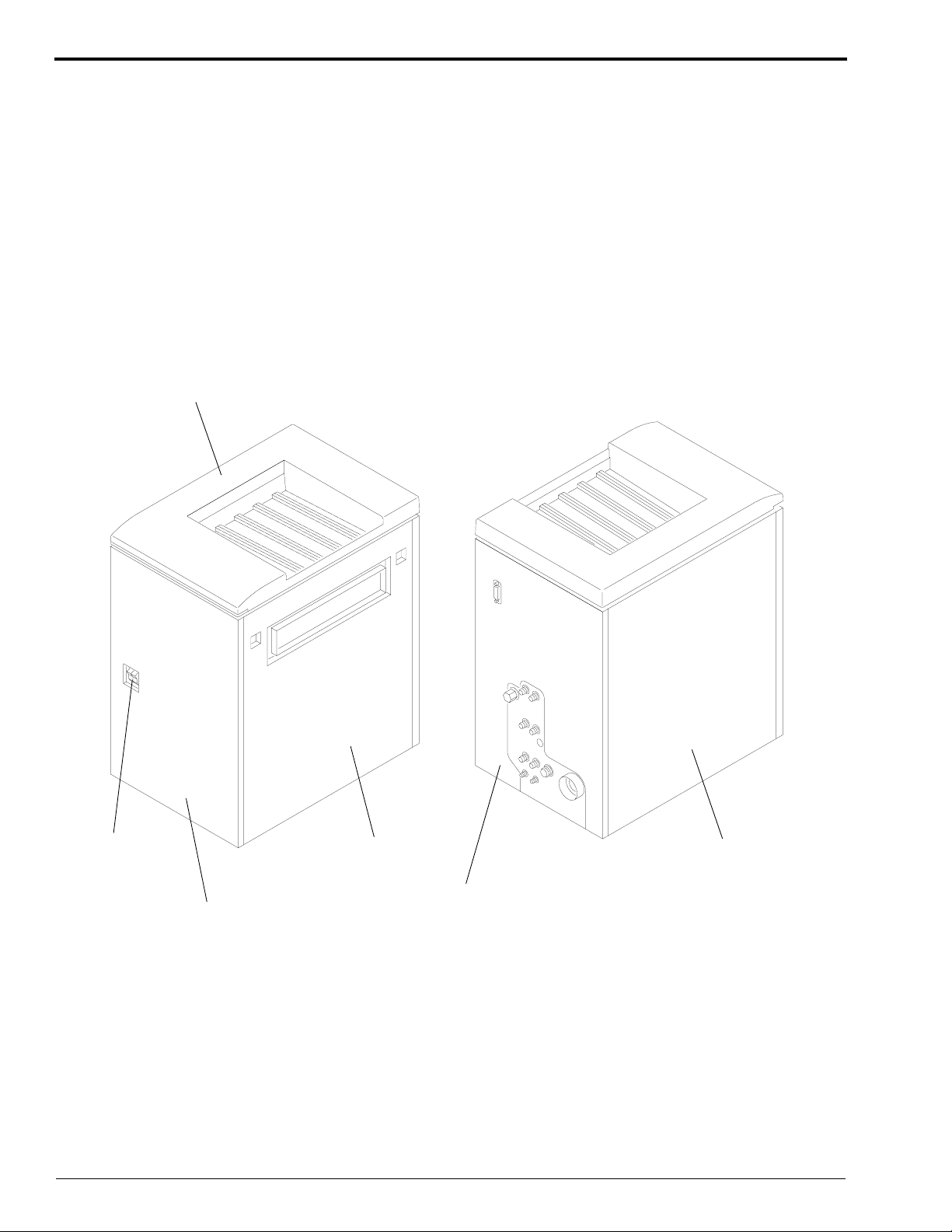
Position and Identification of Subassemblies . . . . . . . . . . . . . . . . . . . . . . . . . . . 2-3
De-energizing and Energizing the PROCESSOR . . . . . . . . . . . . . . . . . . . . . . . 2-5
General Access to the SORTER or to the PROCESSOR . . . . . . . . . . . . . . . . . 2-6
Installing the TOP COVER . . . . . . . . . . . . . . . . . . . . . . . . . . . . . . . . . . . . . . . . 2-7
Replacement of the DIVERTERS or the BEARINGS . . . . . . . . . . . . . . . . . . . . . . . . 2-8
Replacement of a SOLENOID . . . . . . . . . . . . . . . . . . . . . . . . . . . . . . . . . . . . . . . . . . 2-9
Replacement of the INTERLOCK SWITCH . . . . . . . . . . . . . . . . . . . . . . . . . . . . . . . 2-10
Replacement of a MODULE. . . . . . . . . . . . . . . . . . . . . . . . . . . . . . . . . . . . . . . . . . . . 2-11
Replacement of the SENSOR on a MODULE . . . . . . . . . . . . . . . . . . . . . . . . . . . . . . 2-12
Replacement of the ROLLERS
on a LEAD or MAIN MODULE or on the ACCESS DOOR. . . . . . . . . . . . . . . . . 2-14
Replacement of the IDLER ROLLERS and SPRINGS on a MODULE . . . . . . . . . . 2-16
Replacement of the BIN ROLLER . . . . . . . . . . . . . . . . . . . . . . . . . . . . . . . . . . . . . . . 2-17
Replacement of the Front BEARING . . . . . . . . . . . . . . . . . . . . . . . . . . . . . . . . . . . . . 2-17
Replacement of the GEAR or the Back BEARING . . . . . . . . . . . . . . . . . . . . . . . . . . 2-18
Replacement and Adjustment of the DRIVE BELT . . . . . . . . . . . . . . . . . . . . . . . . . . 2-19
Replacement of the DRIVE MOTOR or the GEARBOX. . . . . . . . . . . . . . . . . . . . . . 2-20
Replacement of the MAIN DRIVE SHAFT . . . . . . . . . . . . . . . . . . . . . . . . . . . . . . . . 2-21
Replacement of the WORM GEARS . . . . . . . . . . . . . . . . . . . . . . . . . . . . . . . . . . . . . 2-22
Replacement of the GAS SPRING . . . . . . . . . . . . . . . . . . . . . . . . . . . . . . . . . . . . . . . 2-23
Replacement of the 4000 BOARD or MOTOR CONTROLLER BOARD . . . . . . . . 2-24
Replacement of the 100 BOARD . . . . . . . . . . . . . . . . . . . . . . . . . . . . . . . . . . . . . . . . 2-25
Replacement of the IDLER GEARS. . . . . . . . . . . . . . . . . . . . . . . . . . . . . . . . . . . . . . 2-27
Preventive Maintenance . . . . . . . . . . . . . . . . . . . . . . . . . . . . . . . . . . . . . . . . . . . . . . . 2-28