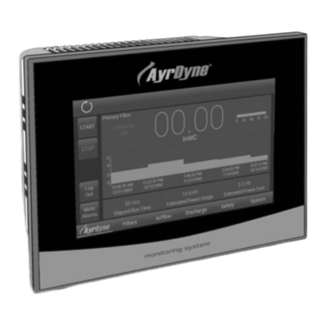
Dentech AYRDYNE 4.0 User manual

www.ayrdyne.com
Installation, Operation, and
Maintenance Manual
4.0

www.ayrdyne.com
Edition notice
DenTech Industrial
1975 N. Reading Rd.
Denver, PA 17517
For customer support, please contact
our service technicians.
Phone: (717) 335-4899
Email: service@dentechindustrial.com
Or visit dentechindustrial.com/customer-support
AD-IOM
Revised December 2021
Printed in the USA.

www.ayrdyne.com
. . . . . . 20
. . . . . . . . 22
. . . . . . . 24
. . . . . 25
. . . . . . . . . 26
. . . . . . . . . . . . . 28
. . . . . . . . . . 30
. . . . . . . . . . 32
. . . . . . 34
36
1.1 Introduction
1.2 Safety
2.1 System
2.2 Filters
2.3 Airow
2.4 Discharge
2.4 Safety
3.1 Alarms
4.1 Removal of HMI
4.2 Installation of HMI
4.3 Installation and Removal of PLC
4.4 Installation and Replacement
of the Battery
5.1 Glossary
TABLE OF CONTENTS
1
1OVERVIEW
2
3
4
5
OPERATION
TROUBLESHOOTING
INSTALLATION &
REMOVAL
GLOSSARY
. . . . . . . . . . . . . . . . 2
. . . . . . . . . . . . . . . . . . . 3
. . . . . . . . . . . . . . . . . . 38
. . . . . . . . . . . . . . 40
. . . . . . . . . . . . 43
. . . . . 44
. . . . . . . . . . . . . . 44
. . . . . . . . . . . . . . . . . 46
. . . . . . . . . . . . . . . . . . 5
. . . . . . . . . . . . . . . . . . 20
. . . . . . . . . . . . . . . . . . 26
. . . . . . . . . . . . . . . . . . 32
. . . . . . . . . . . . . . . . . . 36
2.2.1 Status Bar Overview
2.1.2 Navigation Bar Overview
2.1.3 Main Screen Overview
2.1.4 Metrics (Static Pressure)
2.1.5 Alarms
2.1.6 Settings – Users
2.1.7 Settings – I/O
2.1.8 Settings – Devices
2.2.1 Primary Information
2.2.2 Primary Settings
2.2.3 Primary Solenoids
2.2.4 Secondary Information
2.3.1 Static Pressure
2.3.2 Velocity
2.3.3 VFD Settings
2.4.1 Rotary Valve
2.4.2 Double Dump Valve
2.5.1 Safety Circuit & Isolation Valve
. . . . . . . 6
. . . . . 7
. . . . . . 8
. . . . 10
. . . . . . . . . . . . . 12
. . . . . . . . 14
. . . . . . . . . 16
. . . . . . . 18

www.ayrdyne.com
INTRODUCTION
OVERVIEW
2
The purpose of this document is to outline
proper installation, maintenance, operation,
and care of the AyrDyne®Monitoring System
Human Machine Interface (HMI). This
document is in no way intended to be used
to determine the reliability of this product
outside of its originally intended application.
It is the duty of the end user or integrator to
perform the appropriate risk analysis in order
to determine the relevance of its use within any
specic application.
All pertinent state, regional, and local
safety regulations must be observed when
installing and using this product. For reasons
of safety and to help ensure compliance
with documented system data, only the
manufacturer should perform repairs to
components.
Failure to follow the guidelines outlined in
this manual may result in injury, harm, or
improper operating results. Failure to observe
this information may also result in equipment
damage, premature wear, or failure.

www.ayrdyne.com
SAFETY
SAFETY
OVERVIEW
3
The installation, maintenance, operation, and
care of the AyrDyne®Monitoring System Human
Machine Interface (HMI) should only be performed
by individuals who are qualied and trained
to do so. A “qualied” person in this context is a
person who has skills and knowledge related to the
construction and operation of electrical equipment
and its installation through both work experience
and training. Additionally, a qualied person is one
who has received and undergone safety training
specic to electrical maintenance. Anyone who has
not undergone safety training specic to this system
should not operate or perform maintenance on the
system.
In terms of maintenance of this system, “lock out tag
out” safety protocol applies. This means that any
time maintenance on this system is performed, the
machine must be shut down, unplugged, and tagged
or labeled, explaining that maintenance is taking
place.
DenTech is not liable for any
consequences arising from misuse of
this system. If you are unsure of whether you
are qualied to use or maintain this system, please
contact an electrician or other qualied professional
for assistance. Failure to follow safety protocol for
this and any other system could result in serious
bodily harm or other injury. No responsibility is
assumed by DenTech for any consequences arising
out of the use of this material.
1.2
This symbol indicates that an electrical hazard
exists which could result in personal injury if
the instructions are not followed.
This safety alert symbol is used to alert you
to potential personal injury hazards. Obey all
safety messages that follow this symbol to
avoid possible injury or death.

4www.ayrdyne.com

5
www.ayrdyne.com 5
SYSTEM
This section covers the navigation and operation of the standard AyrDyne Monitoring System. The
operation and functionality of each screen is covered in detail in later sections. The table below shows the
layout of the screens. Available screens depend on system requirements and conguration.
Airow
Safety
System
Filters
Discharge
Alarms
Settings
Overview
Primary Info
Airow Control
Primary Solenoids
Metrics
Primary Settings
VFD Settings
Secondary Info
Alarms monitoring and control
User settings, IO settings, and analog and digital device
settings
Contains all monitoring, settings, and controls related to airow
Contains all monitoring, settings, and controls related to safety
An overview of the system and the rst screen to display
when power is applied
Primary lter dierential pressure monitoring and cleaning
Airow monitoring and control settings
Primary lter cleaning system monitoring and manual
control
Contains system wide monitoring, settings, and controls
Contains all monitoring, settings, and controls related to the lters
Contains all monitoring, settings, and controls related to the discharge system
System Metrics
Primary lter cleaning settings
VFD monitoring and parameter entry
Secondary lter dierential pressure monitoring
OPERATION
5
2.1 OPERATION OVERVIEW
2.1

6www.ayrdyne.com
SYSTEM
6
2.1.1 STATUS BAR OVERVIEW
The status bar is visible in all screens. This bar displays system information, active alarm description, and
corrective action.
USER
Shows the user that is currently logged in.
Pressing the user icon will logout the current
user.
TIME AND DATE
This graphic display shows the internal date
and time. Pressing the time and will display a
pop-up entry page where the date and time
can be adjusted.
LOGO
This graphic display shows the logo
of the company that you may contact
for information on the system, spare or
replacement parts ordering and help with
the system. Pressing the logo will display the
contact information. Once on the information
screen, you may press anywhere on the
screen to return to the home screen.
4
5
3
SYSTEM STATE INDICATOR
This graphic display shows the current
system state.
SYSTEM FAULTS
This text display shows details of any active
faults as well as corrective actions.
1
2
System is Stopped
System is Running
System is Cleaning
System is Faulted
2.1
OPERATION
4 5321

7
www.ayrdyne.com
The navigation bar is located at the bottom of each screen.
The blue line and white font indicate the section currently displayed.
An orange bubble with an exclamation point denotes a warning.
A red bubble with an exclamation point denotes an alarm.
SYSTEM
7
2.1.2 NAVIGATION BAR OVERVIEW
START
This button starts the system.
STOP
On the rst press, this button initiates
shutdown of blower. On the second press,
this button initiates shutdown of components
pertaining to downtime cleaning sequence.
Note:When there is an active fault, the
Clear Faults button displays instead of the
Stop button. After the corresponding fault
conditions have been eliminated, press the
Clear Faults button to clear all faults.
1
2
2 3
3
4
SYSTEM
This button displays system screen.
FILTERS
This button displays the lters screen.
AIRFLOW
This button displays the airow screen.
DISCHARGE
This button displays the discharge screen.
SAFETY
This button displays the safety screen.
4
5
5
6
6
7
7
2.1
OPERATION
1a
a
b
b
c
c

www.ayrdyne.com
SYSTEM
8
2.1.3 MAIN SCREEN OVERVIEW
2.1
OPERATION
9
8
7
10
1
3
2 4 5
6

www.ayrdyne.com
SYSTEM
9
PRIMARY FILTER DP
This numeric display and dial display show
the lter dierential pressure measured
between the dirty and clean sides of the
lters.
PRIMARY FILTER LIFE
This numeric display and dial display show
lter status and remaining life.
DATA PLOT
This graphical display shows the lter
dierential pressure over time. The timeline
view can be changed from one day to six
months.
AIRFLOW
This numeric display and bar graph show the
system static pressure, velocity, or volume
measured.
VFD (Hz)
This numeric display shows VFD output
frequency (measured in Hertz).
UPTIME (Hrs)
This numeric display shows the total time
that the collector has been powered on
(including time running, stopped, and
faulted).
AUTO STOP (Hrs)
This shows the status of the auto stop
Auto Stop Disabled by REM run:
Auto stop is not available when
using the remote run signal.
Schedule Auto Stop:
Press and follow on-screen prompts
to schedule an auto stop.
Auto Stop in hhh:mm:ss:
Shows the remaining hours, minutes,
and seconds until the system
automatically stops.
1
2
3
4
5
6
7
9
8
2.1
a
b
c
RUNNING TIME (%)
This numeric display shows what percentage
of the uptime was spent running.
STOPPED TIME (%)
This numeric display shows what percentage
of the uptime was spent stopped.
FAULTED TIME (%)
This numeric display shows what percentage
of the uptime was spent in a fault condition.
10
OPERATION

www.ayrdyne.com
SYSTEM
10
2.1.4 METRICS (STATIC PRESSURE)
2.1
OPERATION
1
2
3
4
5
6
14
7 8 9 10 11
13
12

www.ayrdyne.com
SYSTEM
11
1
2
5
6
3
4
7
9
8
10
11
12
13
14
RUNTIME (h)
This numeric display shows the total system
runtime for the calendar year (measured in
hours). This metric is not resettable.
SP AVE (in WC or FPM)
This numeric display shows the average
Static Pressure for the calendar year. This
metric is not resettable.
HZ AVE
This numeric display shows the average
blower frequency for the calendar year
(measured in Hertz). This metric is not
resettable.
DP
This numeric display shows the average
dierential pressure for the calendar year.
This metric is not resettable.
CLEAN PULSES
This numeric display shows total cleaning
pulses executed by the lter cleaning
system for the calendar year (if equipped).
MONTH
This column shows the month of year for
the saved metrics. Blue numbers in the
corresponding rows represent the current
month.
RUN
This numeric display shows the total system
runtime for the corresponding month
(measured in hours). This metric is not
resettable.
SP OR FPM
This numeric display shows the average
static pressure (SP) inWC or feet per minute
(FPM), depending on system conguration,
for the corresponding month. This metric is
not resettable.
HZ
This numeric display shows the average
blower frequency for the corresponding
month (measured in Hertz). This metric is
not resettable.
DP
This numeric display shows the average
dierential pressure for the corresponding
month. This metric is not resettable.
PULSES
This numeric display shows the total
number of cleaning pulses for the
corresponding month. This metric is not
resettable.
POWER SAVINGS TOTAL (USD)
This numeric display, visible when equipped
with a VFD, shows estimated power usage
cost savings in comparison to the usage of a
motor starter.
POWER SAVINGS YEAR-TO-DATE (USD)
This numeric display, visible when equipped
with a VFD, shows estimated power usage
cost savings on a yearly basis in comparison
to the usage of a motor starter.
ESTIMATED POWER USAGE MONTH
DISPLAY
This bar graph shows estimated power
usage each month if equipped with a VFD.
2.1
OPERATION

www.ayrdyne.com
SYSTEM
12
ACTIVE
This tab shows active alarms with a time
stamp of when the alarm occurred and
description of that alarm.
1
2.1
2.1.5 ALARMS
OPERATION
1

www.ayrdyne.com
SYSTEM
13
HISTORY
This tab shows previously active alarms
with a time stamp and description of each
alarm.
RELOAD
This button reloads the alarm history on the
screen.
DELETE
This button deletes the alarm history on the
screen.
2
3
4
2.1
OPERATION
2
3
4

www.ayrdyne.com
SYSTEM
14
2.1.6 SETTINGS - USERS
2.1
OPERATION
1a
2 3
ci
cii
ciii
1b 1c 1d

www.ayrdyne.com
AUTO LOGON
Allows the manager to set up Auto Logon.
When enabled, the system will attempt to
log on the user as specied in the user and
password elds. Note that these elds are
NOT linked to the user administration table.
Thus changing user names and passwords
in the table will break the auto logon feature
until the user and password are updated in
the auto logon elds.
DEFAULT USERS AND PASSWORDS
The system ships with the default users and
passwords below. Make sure to make your
passwords secure and document them.
User: maint
Password: 123
User: manager
Password: 123
User: operator
Password: 123
To create a new user:
1. Log in as a manager
2. Press on an empty row in the table
3. Assign a user, password, group, and
logo time
To change a user’s password:
1. Press on “Password”
2. Follow on-screen prompts
SYSTEM
15
1 2
3
USER ADMINISTRATION TABLE
This table allows administration of users
and permissions.
User:
Shows the users in the system.
Password:
Shows the password for the
respective user.
Group:
Shows the group for the respective
user.
Manager: Can perform any
operation on the system as
well as add or remove users,
change group assignments,
and change passwords for
any user.
Maintenance: Can
perform any operation
except for user
administration. May change
their own password or logo
time.
Operator: Can change
settings on the system that
are not part of the airow
and balancing. May change
their own password or logo
time.
Logotime:
Shows the inactivity time in minutes
that the respective user has
prior to being logged o
automatically.
2.1
a
a
b
c
b
c
d
OPERATION
i.
ii.
iii.

www.ayrdyne.com
SYSTEM
16
2.1.7 SETTINGS - I/O
2.1
OPERATION
1 32

www.ayrdyne.com
SYSTEM
17
1
2
3
DIGITAL IN
This graphic display shows the status of
each input. A gray number indicates that
the corresponding input is OFF; a yellow
number indicates that the corresponding
input is ON. Each input may also be ipped
by the “Flip” button immediately to the right.
When the “Flip” button is gray, the input
remains as wired; when the “Flip” button is
blue, the input state is ipped. The number
immediately to the right of the “Flip” button
shows the status of the input as evaluated in
the program.
DIGITAL OUT
This graphic display shows the status of
each output. A gray number indicates that
the corresponding output is OFF; a yellow
number indicates that the corresponding
output is ON.
ANALOG IN / OUT
This graphic display shows the signal of
each analog input / output from 0 – 100%.
2.1
OPERATION

18 www.ayrdyne.com
SYSTEM
2.1
OPERATION
2.1.8 SETTINGS - DEVICES
5
6
7
2
3
41
Table of contents
Other Dentech Measuring Instrument manuals
