Geokon 3900 User manual

Instruction Manual
Model 3900
Embedment Strain Gauge
No part of this instruction manual may be reproduced, by any means, without the written consent of Geokon®.
The information contained herein is believed to be accurate and reliable. However, Geokon®assumes no responsibility for errors,
omissions or misinterpretation. The information herein is subject to change without notification.
Copyright © 2007-2019 by Geokon®
(Doc REV E, 04/30/19)


Warranty Statement
Geokon warrants its products to be free of defects in materials and workmanship, under normal
use and service for a period of 13 months from date of purchase. If the unit should malfunction,
it must be returned to the factory for evaluation, freight prepaid. Upon examination by Geokon,
if the unit is found to be defective, it will be repaired or replaced at no charge. However, the
WARRANTY is VOID if the unit shows evidence of having been tampered with or shows
evidence of being damaged as a result of excessive corrosion or current, heat, moisture or
vibration, improper specification, misapplication, misuse or other operating conditions outside of
Geokon's control. Components which wear or which are damaged by misuse are not warranted.
This includes fuses and batteries.
Geokon manufactures scientific instruments whose misuse is potentially dangerous. The
instruments are intended to be installed and used only by qualified personnel. There are no
warranties except as stated herein. There are no other warranties, expressed or implied, including
but not limited to the implied warranties of merchantability and of fitness for a particular
purpose. Geokon is not responsible for any damages or losses caused to other equipment,
whether direct, indirect, incidental, special or consequential which the purchaser may experience
as a result of the installation or use of the product. The buyer's sole remedy for any breach of this
agreement by Geokon or any breach of any warranty by Geokon shall not exceed the purchase
price paid by the purchaser to Geokon for the unit or units, or equipment directly affected by
such breach. Under no circumstances will Geokon reimburse the claimant for loss incurred in
removing and/or reinstalling equipment.
Every precaution for accuracy has been taken in the preparation of manuals and/or software,
however, Geokon neither assumes responsibility for any omissions or errors that may appear nor
assumes liability for any damages or losses that result from the use of the products in accordance
with the information contained in the manual or software.

TABLE of CONTENTS
1. INTRODUCTION .................................................................................................................................................. 1
2. INSTALLATION.................................................................................................................................................... 1
3. TAKING READINGS ............................................................................................................................................ 1
3.1 CIRCUIT DIAGRAM .............................................................................................................................................. 2
3.2 USING THE GEOKON GK-502 READOUT BOX ..................................................................................................... 2
4. DATA REDUCTION.............................................................................................................................................. 3
4.1 DISPLACEMENT CALCULATION ........................................................................................................................... 3
4.2 STRAIN CALCULATION........................................................................................................................................ 3
4.3 TEMPERATURE CORRECTION FACTOR................................................................................................................. 4
APPENDIX A. SPECIFICATIONS .......................................................................................................................... 5
APPENDIX B. THERMISTOR TEMPERATURE DERIVATION ...................................................................... 6
APPENDIX C. TYPICAL CALIBRATION REPORT ........................................................................................... 7
FIGURES
FIGURE 1-CIRCUIT DIAGRAM ....................................................................................................................................... 2
FIGURE 2-TYPICAL CALIBRATION REPORT .................................................................................................................. 7
TABLES
TABLE 1-INPUT CONNECTIONS .................................................................................................................................... 1
TABLE 2-SPECIFICATIONS ............................................................................................................................................ 5
TABLE 3-THERMISTOR RESISTANCE VERSUS TEMPERATURE ...................................................................................... 6
EQUATIONS
EQUATION 1-DISPLACEMENT....................................................................................................................................... 3
EQUATION 2-STAIN CALCULATION WITH TEMPERATURE CORRECTION....................................................................... 4
EQUATION 3-RESISTANCE TO TEMPERATURE .............................................................................................................. 6

1
1. INTRODUCTION
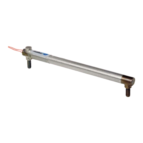
The Model 3900 Embedment Strain Gauge is designed for the measurement of dynamic strains
in concrete structures and soils. It comprises a full-bridge strain gauge proving ring element
coupled in series with a tension spring which is stretched between two end flanges. An outer
PVC tube sealed with O-rings provides a waterproof housing. The end flanges are embedded and
move in accordance with the surrounding material. The voltage signals from the strain gauge are
transmitted via cable to the readout location.
The strain gauge can be read out by means of the Geokon Model 502 Readout Box or by a
applying a 2 to 12 Volt excitation to the input leads and reading the corresponding millivolt
output. The output at full range is approximately 3 mV/V. The standard wiring for use with the
GK-502 readout box is configured to compensate for the use of long cables by the remote
sensing of the input voltage at the sensor. A Thermistor is included inside the sensor to measure
temperatures. This requires a cable with four shielded pairs of conductors.
2. INSTALLATION
The embedment gauge is delivered with the sensor set at an approximately midrange position
ready for installment. The standard range is ± 2500 microstrains. (Other ranges are available).
An initial test can be conducted by connecting the strain gauge to the GK-502 Readout Box or to
a regulated voltage supply. Movement of the end flanges should produce a corresponding change
in the gauge output. At no time should the end flanges be twisted or pulled beyond the range of
the sensor as this could permanently damage the gauge.
The gauge should be installed directly in the concrete or soil by hand. Large aggregate should be
removed from the area immediately surrounding the sensor. The use of vibrators immediately
next to the gauge should be avoided. The standard cable has a thick PVC jacket and can be
placed directly in the concrete.
3. TAKING READINGS
Connect the ten-pin connector to the GK-502 readout box or connect the bare wires to a voltage
supply and millivoltmeter as follows:
Bendix Pin
Circuit Label
Description
Geokon Purple Cable
A
S-
Bridge Output -
White's Black
B
P+
Bridge Excitation +
Red
C
P-
Bridge Excitation -
Red's Black
D
S+
Bridge Output +
White
E
NC
No Connection
NC
F
G
Ground for shield
Shield
G
T
Thermistor
Blue
H
T
Thermistor
Blue’s Black
J
RS+
Remote Sense +
Green
K
RS-
Remote Sense -
Green's Black
Table 1 - Input Connections

2
3.1 Circuit Diagram
P-
P+
S+
S-
RS+
RS-
G
Strain Gage
Figure 1 - Circuit Diagram
3.2 Using the Geokon GK-502 Readout Box
The user is referred to the GK-502 Instruction Manual for additional information on the
following instructions:
1) Connect the embedment gauge to the readout box by means of the 10-pin input connector.
2) Press the ‘ON/OFF’ button power switch to the "ON" position.
3) Press the ‘UNITS’ button until the UNITS displayed are mV/V.
4) Read the display and record.
5) See the GK-502 Instruction Manual for further instructions.

3
4. DATA REDUCTION
4.1 Displacement Calculation
The basic units utilized by Geokon for measurement and reduction of data from Model 3900
Embedment Strain Gauges are mV/V
If a GK-502 readout box is in use mV/V can be displayed directly.
The displacement Dis given by the equation:
D = ((R1- R0) ×C
Equation 1 - Displacement
Where;
D is the displacement in the units given on the calibration report provided with the instrument.
R0is the initial GK-502 reading in mV/V.
R1is the current GK-502 reading in mV/V.
C is the calibration factor in millimeters/mV/V, or inches/mV/V as supplied on the Cal Sheet.
(See Appendix C. for a sample calibration report.)
If a regulated power supply and a millivoltmeter are used, then calculate the mV/V by dividing
the displayed millivolt output by the voltage input measured at the sensor using the remote signal
leads, (Green and Green’ Black).
4.2 Strain Calculation
To calculate the strain ε,divide the measured displacement Dby the gauge length L.
The standard length for Lis 203 mm (Eight inches)
Example: Using a GK-502, R0= -0.8640 and R1= -0.5563, C = 0.05193 inches/mV/V.
Strain ε = ((-0.5563-(-0.8640) x 0.05193/8 = +2000 microstrain (tension)
Note that an increasing reading denotes a tensile strain.

4
4.3 Temperature Correction Factor
Tests have shown that the temperature effect is such that the embedment gauge reading goes
down (compression) as the temperature goes up and the required temperature correction factor is
plus six microstrains per °C.
So, for example, using the GK-502 (displaying mV/V) to take the readings, and a standard eight-
inch-long gauge, where Cis given in inches/mV/V, the calculation for strain S, corrected for
temperature change (T1- T0)measured in degrees Centigrade, is:
S = (R1- R0) ×C/8 + 6(T1- T0) microstrain
Equation 2 - Stain Calculation with Temperature Correction
Where Cis given in mm/mv/v the equivalent equation is
S = ((R1- R0) ×C/203 + 6(T1- T0) microstrain

5
APPENDIX A. SPECIFICATIONS
Standard Range¹: 5000 microstrain
Accuracy: ± 0.1% FS
Linearity: <0.5% FSR
Resolution: ± 0.025% FSR
Repeatability: 0.1% FSR
Temperature Effect: 0.12% FSR/°C
Temperature Range:
−20 to +80° C
0 to 110° F
Active Gauge Length2203 mm
Input Resistance: 350Ω
Output Resistance: 350 Ω
Excitation Voltage: 2 to 15 V DC
Maximum Excitation Voltage: 30 V
Cable Type:
Four twisted pair (eight conductor) 22 AWG
Foil shield, PVC jacket, nominal OD=9.5 mm (0.375")
Table 2 - Specifications
Notes
¹ Other ranges are available on request.
2 Other gauge lengths available on request.

6
APPENDIX B. THERMISTOR TEMPERATURE DERIVATION
Thermistor Type: YSI 44005, Dale #1C3001-B3, Alpha #13A3001-B3
Resistance to Temperature Equation:
T= 1
A+B(LnR)+C(LnR)3-273.15 °C
Equation 3 - Resistance to Temperature
Where;
T =Temperature in °C.
LnR =Natural Log of Thermistor Resistance
A =1.4051 ×10⁻³
B =2.369 ×10⁻⁴
C =1.019 ×10⁻⁷
Note: Coefficients calculated over the −50 to +150°C. span.
Ohms
Temp
Ohms
Temp
Ohms
Temp
Ohms
Temp
Ohms
Temp
201.1K
-50
16.60K
-10
2417
+30
525.4
+70
153.2
+110
187.3K
-49
15.72K
-9
2317
31
507.8
71
149.0
111
174.5K
-48
14.90K
-8
2221
32
490.9
72
145.0
112
162.7K
-47
14.12K
-7
2130
33
474.7
73
141.1
113
151.7K
-46
13.39K
-6
2042
34
459.0
74
137.2
114
141.6K
-45
12.70K
-5
1959
35
444.0
75
133.6
115
132.2K
-44
12.05K
-4
1880
36
429.5
76
130.0
116
123.5K
-43
11.44K
-3
1805
37
415.6
77
126.5
117
115.4K
-42
10.86K
-2
1733
38
402.2
78
123.2
118
107.9K
-41
10.31K
-1
1664
39
389.3
79
119.9
119
101.0K
-40
9796
0
1598
40
376.9
80
116.8
120
94.48K
-39
9310
+1
1535
41
364.9
81
113.8
121
88.46K
-38
8851
2
1475
42
353.4
82
110.8
122
82.87K
-37
8417
3
1418
43
342.2
83
107.9
123
77.66K
-36
8006
4
1363
44
331.5
84
105.2
124
72.81K
-35
7618
5
1310
45
321.2
85
102.5
125
68.30K
-34
7252
6
1260
46
311.3
86
99.9
126
64.09K
-33
6905
7
1212
47
301.7
87
97.3
127
60.17K
-32
6576
8
1167
48
292.4
88
94.9
128
56.51K
-31
6265
9
1123
49
283.5
89
92.5
129
53.10K
-30
5971
10
1081
50
274.9
90
90.2
130
49.91K
-29
5692
11
1040
51
266.6
91
87.9
131
46.94K
-28
5427
12
1002
52
258.6
92
85.7
132
44.16K
-27
5177
13
965.0
53
250.9
93
83.6
133
41.56K
-26
4939
14
929.6
54
243.4
94
81.6
134
39.13K
-25
4714
15
895.8
55
236.2
95
79.6
135
36.86K
-24
4500
16
863.3
56
229.3
96
77.6
136
34.73K
-23
4297
17
832.2
57
222.6
97
75.8
137
32.74K
-22
4105
18
802.3
58
216.1
98
73.9
138
30.87K
-21
3922
19
773.7
59
209.8
99
72.2
139
29.13K
-20
3748
20
746.3
60
203.8
100
70.4
140
27.49K
-19
3583
21
719.9
61
197.9
101
68.8
141
25.95K
-18
3426
22
694.7
62
192.2
102
67.1
142
24.51K
-17
3277
23
670.4
63
186.8
103
65.5
143
23.16K
-16
3135
24
647.1
64
181.5
104
64.0
144
21.89K
-15
3000
25
624.7
65
176.4
105
62.5
145
20.70K
-14
2872
26
603.3
66
171.4
106
61.1
146
19.58K
-13
2750
27
582.6
67
166.7
107
59.6
147
18.52K
-12
2633
28
562.8
68
162.0
108
58.3
148
17.53K
-11
2523
29
543.7
69
157.6
109
56.8
149
Table 3 - Thermistor Resistance Versus Temperature
55.6
150

7
APPENDIX C. TYPICAL CALIBRATION REPORT
Figure 2 - Typical Calibration Report
Table of contents
Other Geokon Measuring Instrument manuals

Geokon
Geokon 4430 User manual

Geokon
Geokon 6165 User manual

Geokon
Geokon 4200ER User manual

Geokon
Geokon 6300 User manual

Geokon
Geokon 4300 Series User manual

Geokon
Geokon 4500S User manual

Geokon
Geokon 6150F User manual

Geokon
Geokon 4420 User manual

Geokon
Geokon 1900 User manual

Geokon
Geokon 3400 Series User manual

Geokon
Geokon 4425 User manual

Geokon
Geokon 4425 User manual

Geokon
Geokon 4675LV User manual

Geokon
Geokon GK-604D User manual

Geokon
Geokon 4500 Series User manual

Geokon
Geokon 4500 Series User manual

Geokon
Geokon GK-604D User manual

Geokon
Geokon 4580 User manual

Geokon
Geokon 4911 User manual

Geokon
Geokon 4400 User manual