Deprag MINIMAT-ED Series User manual

014161en
Operating Instruction Booklet
- Original instructions -
Digital Electric Screwdriver
MINIMAT-ED
330EG36-0012 440000 A
330EG36-0018 440000 B
330EG36-0048 440000 C
330EG36-0032 440000 E
NOTICE ALL DOCUMENTATIONS !
Before beginning work this operating instruction booklet and the enclosed
safety instructions (no. 016000, pink-colored booklet) have to be read through
carefully. Always follow the instructions during operation. Give this operating in-
struction booklet and the appropriate safety instructions to the operator.

Contents
1SIGNAL WORD AND SYMBOL DEFINITION...............................................................4
2SAFETY INSTRUCTIONS .............................................................................................5
2.1. Safety Instructions for Electronic Screwdrivers ..........................................................5
3INTENDED USE ............................................................................................................5
4DELIVERY CAPACITY..................................................................................................6
5GENERAL......................................................................................................................6
6OPERATION..................................................................................................................7
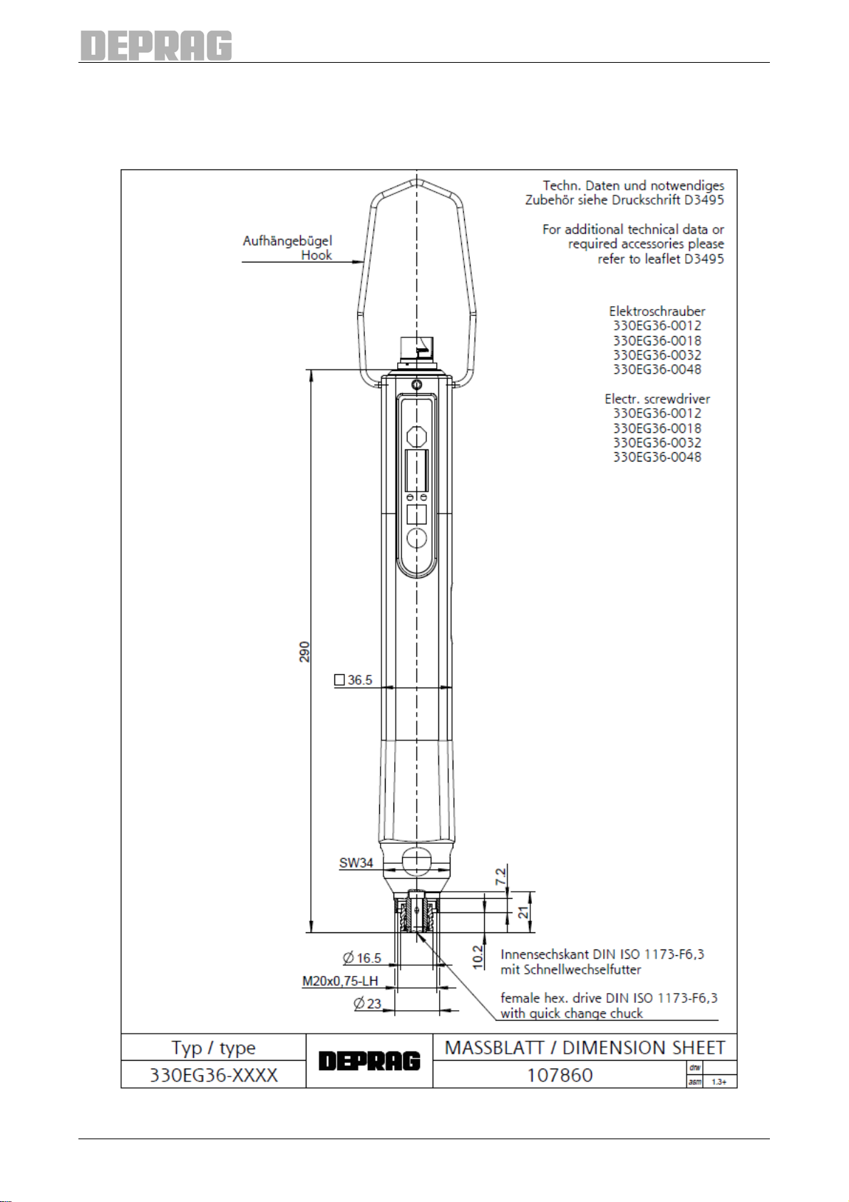
6.1. Dimensional Drawing .................................................................................................7
6.2. Assembly Instructions ................................................................................................8
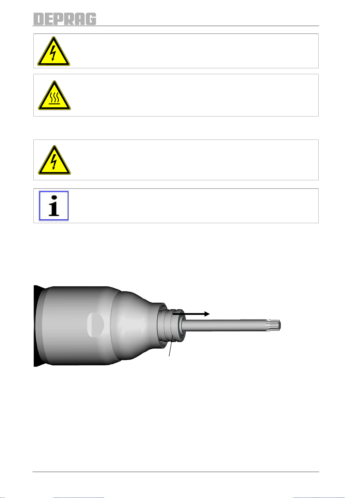
6.3. Change of Bits..........................................................................................................10
7OPERATION................................................................................................................11
7.1. Operating element....................................................................................................11
7.1.1 Status LEDs...........................................................................................................11
7.1.2 Function buttons.....................................................................................................11
7.1.3 Display ...................................................................................................................12
7.2. Screwdriver start ......................................................................................................12
7.3. Program selection / Torque setting...........................................................................12
7.4. Menu operation ........................................................................................................12
7.5. Menu structure .........................................................................................................13
7.6. Pressure test function...............................................................................................14
7.7. Display test...............................................................................................................14
8DESCRIPTION OF THE SETTINGS............................................................................16
9SCREWDRIVING TEMPLATE.....................................................................................17
9.1. Description of the screwdriving sequences ..............................................................17
9.2. Screw assembly program.........................................................................................17
9.3. Loosening program ..................................................................................................18
10 MAINTENANCE AND UPKEEP ................................................................................19
11 ERROR DISPLAY AND TROUBLESHOOTING........................................................20
11.1. System error...........................................................................................................20
11.2. Error in the screwdriving sequence........................................................................21
12 TROUBLESHOOTING...............................................................................................22
13 ACCESSORIES - OPTIONAL EQUIPMENT .............................................................23
13.1. Required accessories.............................................................................................23
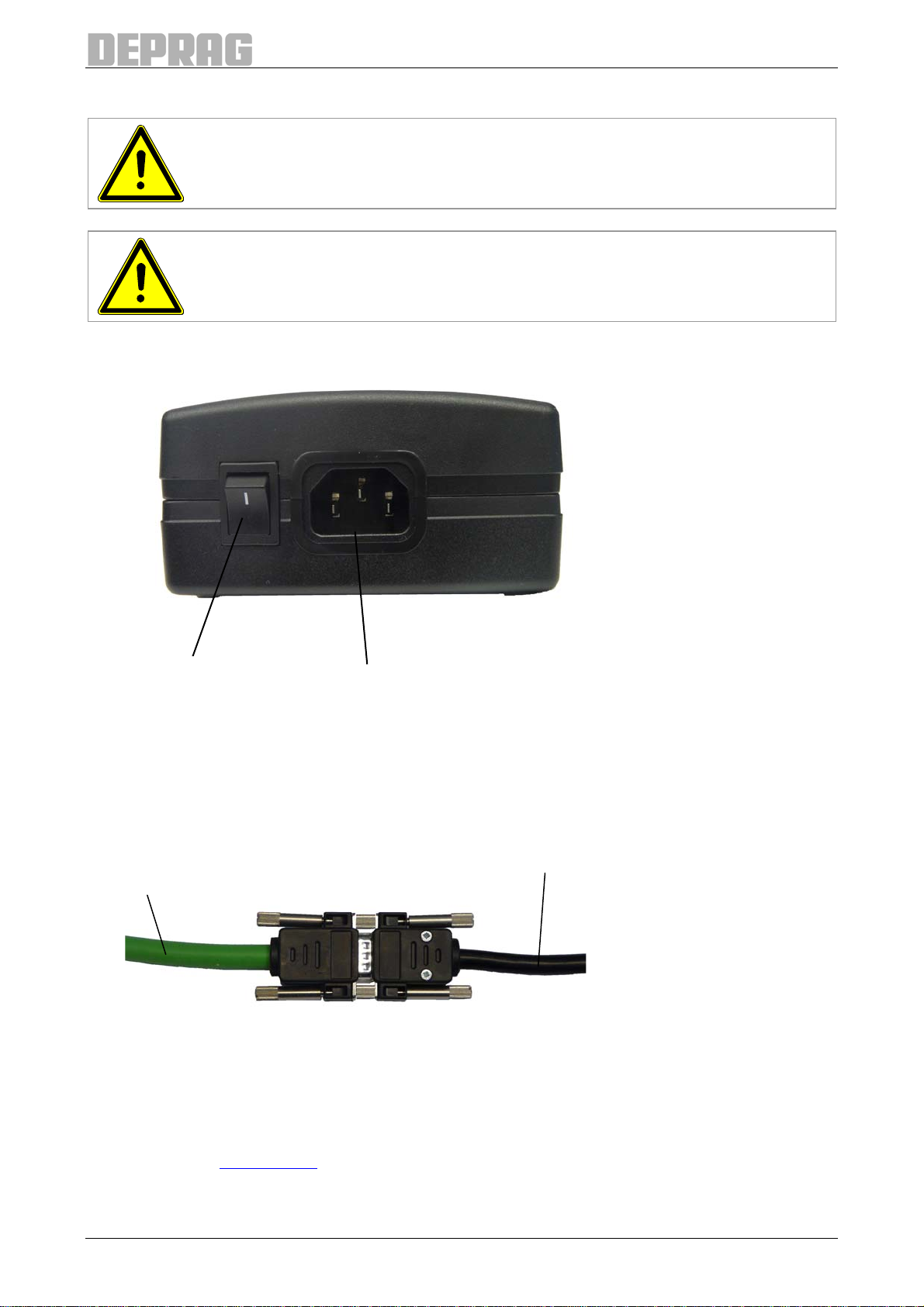
13.1.1 Motor cable ..........................................................................................................23
13.1.2 Power unit ............................................................................................................23
13.1.3 Power supply cable..............................................................................................23
13.2. Optional accessories..............................................................................................24
13.2.1 Spring sleeve .......................................................................................................24
13.2.2 EF-Control............................................................................................................25
13.2.3 Screwdriver adapter.............................................................................................25
13.2.4 Balancer...............................................................................................................26
13.2.5 Additional accessories..........................................................................................26
14 SHUT DOWN AND STORAGE..................................................................................27
2

15 TECHNICAL DATA....................................................................................................27
16 EC-CONFORMITY DECLARATION..........................................................................28
17 SERVICE LOCATIONS AND AUTHORIZED PARTNERS........................................29
List of illustrations
Illustration 1 – Dimensional Drawing....................................................................................7
Illustration 2 – Power supply connections............................................................................8
Illustration 3 – Connection of motor cable to the power unit ................................................8
Illustration 4 – Installation ....................................................................................................9
Illustration 5 – Change of Bits............................................................................................10
Illustration 6 – Operating element......................................................................................11
Illustration 7 – EF-Control ComCenter ED.........................................................................25
Illustration 8 – Clamping area for screwdriver adapter.......................................................25
List of tables
Tables 1: Scope of Delivery ..............................................................................................6
Tables 2: Status LEDs.....................................................................................................11
Tables 3: Function buttons..............................................................................................11
Tables 4: Menu structure.................................................................................................13
Tables 5: Description of the settings ...............................................................................16
Tables 6: System error....................................................................................................20
Tables 7: Error in the screwdriving sequence .................................................................21
Tables 8: Fault solutions .................................................................................................22
3

1 Signal Word and Symbol Definition
The signal words and symbols used in the technical documentation (safety instructions,
operating instruction booklet, etc.) have the following meaning:
DANGER
Indicates an immediate danger which causes serious injuries or even
death if not avoided.
WARNING
Indicates a threatening danger which can cause serious injuries or even
death if not avoided.
CAUTION
Indicates a danger or unsafe procedure which can cause injuries to a per-
son or material damages if not avoided.
NOTICE
Indicates a potentially dangerous situation which can cause damage to
the product or its surroundings if not avoided.
IMPORTANT
Indicates tips and other useful information.
In each case the symbol used does not replace the safety text. The text must always be
read fully. In some cases other symbols will be used with the signal words.
4

2 Safety Instructions
2.1. Safety Instructions for Electronic Screwdrivers
Disconnect the machine from the power supply, prior to changing bits.
Do not wear loose clothing or jewelry; for movable parts can seize them.
Wear a hairnet, if operator has long hair.
Keep hands off the installed bit or socket.
Injury is possible, if the driver reacts with an unexpected motion or when driver is used
with a broken bit.
Injury is possible, if the driver or the installed bits/socket reacts with an unexpected mo-
tion.
When using tool with a bit-adapter or bit-extension (i.e. Magnetic Bit holder), make sure
that those items are in good condition and well suited for the application with this tool.
When installing driver into a support arm, make sure that the tool is rigidly mounted.
When not using any support arm or stand, place both feet securely on the floor. This
enables the Operator to easily absorb any tool reaction force.
Install a side-handle or counter-holder to the driver, if the reaction force
cannot safely be absorbed by operator.
After turning off the tool, the bit will continue to rotate (inertia).
In no case is it permissible to exceed the rated voltage.
In the case of a power interruption, it is necessary to reset the controller.
CAUTION
The screwdriver will heat-up in relation to its average load respectively
sequence of operation. If the selection of the type of screwdriver is incor-
rectly or its operation is not appropriate for the application, the tool might
overheat which could result in injuries (burnings).
3 Intended Use
DEPRAG MINIMAT-ED Screwdrivers of straight design are intended to be used only for
manual assemblies, preferably for vertical applications. They are exclusively designed for
screw-assembly in an industrial environment.
The digital electric screwdriver is also designed for the operation in electrostatic exposed
areas and where an ESD-safe assembly is required (specifications according to DIN EN
61340-5-1).
Using this electric screwdriver does not exclude employing all other required or necessary
ESD avoidance measures (requirements according to DIN EN 61340-5-1 and VDE 0100).
Connection and measurement of the electric screwdriver are to be carried out according to
chapter 6.
IMPORTANT
Start-up and continuous operation of the electric screwdriver are only
allowed in conjunction with a DEPRAG power unit.
5

4 Delivery Capacity
Check that the shipment is complete and that there have been no damages in transit.
Quantity Name Order No.
1 Electric Screwdriver 440000 A / B / C / E
1 Operating instruction booklet 014161
1 Safety Instruction Booklet 016000
Tables 1: Scope of Delivery
5 General
The essential characteristics of this screwdriver series are:
required torque can be set in the chosen unit (Nm, Ncm or in.lbs) by button directly
on the screwdriver
digital display that shows the set torque directly on the screwdriver
trigger start or push-to-start options
integrated quick change chuck for simple tool change
balancer hook
low noise operation
ergonomic rectangular housing design
less space required due to integrated controller
torque-accuracy like the reliable DEPRAG-Control Screwdriver
Password protection against unauthorized parameter change
Status and results display on the screwdriver
Suitable for the use in electrostatic exposed areas
integrated diagnostics functions
The DEPRAG MINIMAT-ED Screwdriver is designed for use in an industrial environment
for a maximum torque of 1.2 / 1.8 / 3.2 or 4.8 Nm (depending on the screwdriver type
chapter 15 Technical Data).
For operation of the electric screwdriver, the following components are required:
MINIMAT-ED Screwdriver 330EG36-...
Power unit
power supply cable
Motor cable (available in different lengths)
For order no. of the power unit, power supply cable and the motor cable chapter 13.1
Required accessories
The screwdriving sequence will be initiated by either push-to-start or trigger start. Selection
and/or change of the screwdriving sequence can be carried out via a menu function di-
rectly on the screwdriver.
6

6 Operation
6.1. Dimensional Drawing
Illustration 1 – Dimensional Drawing
7

6.2. Assembly Instructions
CAUTION
The electric screwdriver may only be operated by competent personnel.
WARNING
Danger to life from electric shock!
Disconnect the machine from the power supply before any assembly, instal-
lation or maintenance work.
ON/OFF switch power cable connection
Illustration 2 – Power supply connections
Proceed in the following order when installing:
(see Illustration 4 – Installation)
1. Connect the electric screwdriver to the motor cable.
2. Connect the motor cable to the power unit.
Motor cable of the Power unit cable
electric screwdriver
Illustration 3 – Connection of motor cable to the power unit
3. Connect the power cable to the power unit.
4. Connect the power cable to the power network.
5. Switch on the power unit.
6. Carry out required settings on the screwdriver
(Chapter 7Operation).
8

WARNING
Disconnect screwdriver from power supply before changing or mount-
ing the screwdriver tool (bit, socket) or accessory.
CAUTION
Screwdriver will heat-up in relation to its average load respectively se-
quence of operation If the selection of the type of screwdriver is incorrectly
or its operation is not appropriate for the application, the tool might overheat
which could result in injuries (burnings).
6.3. Change of Bits
DANGER
Machine can start. Serious injuries could be caused.
Disconnect the machine from the electricity supply.
IMPORTANT
Use perfect inserting tools (e.g. bits) and connecting components with
DIN 3126 – E6.3 (¼”) external hexagon end only.
The EC-screwdriver is equipped with a quick change chuck.
1. Pull the sleeve forward towards the tip of the screwdriver spindle and insert new bit or
remove old bit.
2. Push the new bit (E6.3 (¼“)) into the hex until it locks.
3. Let sleeve snap back.
sleeve
Illustration 5 – Change of Bits
10

7 Operation
7.1. Operating element
function buttons
status LEDs
7 segment display
Illustration 6 – Operating element
7.1.1 Status LEDs
Colour Name Nomenclature
green Status OK last screw assembly OK
red Status NOT
OK last screw assembly NOT OK
Tables 2: Status LEDs
IMPORTANT
If both LEDs flash at the same time program selection is selected on the
screwdriver.
When moving into the settings menu both LEDs switch off.
7.1.2 Function buttons
Symbol Description Meaning
Start Start screwdriving program (only if the screwdriver is set to but-
ton start, see ...link)
Reversal Change between assembly and loosening programs. For every
one of the 5 screw assembly programs (programs 1-5) there is
a corresponding loosening program (programs 6-10).
Program se-
lection / Menu A short press of the button moves into the program selection
torque setting, a long press of the button moves into the set-
tings menu.
A long press of the button is indicated by a line in the upper
edge of the display (¯ ¯ ¯).
Tables 3: Function buttons
11

IMPORTANT
Differing assignments of the function buttons will be described in the appro-
priate places.
7.1.3 Display
The display shows results and the menu.
During normal operation the screw assembly results are shown on the display:
If assembly was OK, the torque result of the last screwdriving step of the assembly is dis-
played in the selected torque unit. If there were errors, the error number is displayed (see
...link).
If a system error occurs the text “Err” and a 3 digit error number are displayed alternately.
For error descriptions see ...link.
IMPORTANT
Differing displays are described in the appropriate places.
7.2. Screwdriver start
Depending on the selected torque mode, the MINIMAT-ED Digital Electric Screwdriver
starts by push-to-start or pushing the button .
To change between the screw assembly and loosening program press button .
Program assignment:
fasten 1 2 3 4 5
loosen 6 7 8 9 10
7.3. Program selection / Torque setting
Depending on the torque mode selected (see 8 Description of the settings) a pre-set pro-
gram can be selected via program selection and the torque can be adjusted.
As follows:
• A short press on button , both LEDs flash.
• Use the buttons (-) and (+) to select the required program / torque
• To quit program selection – a short press on button , both LEDs go out and the
number of the currently selected screw assembly or loosening program is dis-
played (Pxx).
7.4. Menu operation
To access the menu press and hold button , both LEDs go out and the current menu is
shown on the display (e.g. F01).
A short press of the button changes the selected menu or selected parameter, a longer
press of the button and you quit the selected menu or selected parameter.
Use the buttons (-) and (+) to select the required menu item or parameter.
12

7.5. Menu structure
MAIN MENU FUNCTION SETTINGS / CRITERIA
F01 Displays version of power
unit --
F02 Displays version of
screwdriver logic --
F03 Displays version of dis-
play --
F04 Torque unit setting 1: Nm
2: Ncm
3: in-lbs
F05 Start type setting 1: Push-to-start
2: Button
F06 Delay interrupt setting 0-30 *100ms
F07 Torque mode setting 1: Torque setting in torque unit steps
2: Select between 5 adjustable screw assembly and
loosening programs
F08 Password setting 0: No password
<>0: Password
F09 Main rotational direction
setting 1: Right
2: Left
F10 Display test setting 1: Switch off display test
2: Switch on display test
F11 Pressure test function see 7.6 Pressure test function
F12-20 reserved --
F21 Program 1 setting
A1 Speed
A2 Shut-off angle
F22 Program 2 setting
A3 Shut-off torque
Search run
A4 Speed
F23 Program 3 setting
A5 Shut-off torque Screw assembly to
torque
A6 Direction
F24 Program 4 setting
A7 Speed
A8 Shut-off angle
Screw assembly /
Loosening to angle
F25 Program 5 setting
F26 Program 6 setting
F27 Program 7 setting
A1 Speed
F28 Program 8 setting
A2 Shut-off angle Loosening to angle
F29 Program 9 setting
F30 Program 10 setting
Tables 4: Menu structure
13

7.6. Pressure test function
NOTE
In normal operation the screwdriver starts once the turn-on threshold has
been exceeded and stops once it has dropped below the turn-off threshold.
Test the function of the push-to-start as follows:
1. start test function via menu function F11.
2. hold the screwdriver vertically.
3. in the lower segment of the display a line appears ( | | |).
4. push down on the screwdriver.
5. when the turn-off threshold has been exceeded a second line appears ( | | |).
6. when the turn-off threshold has been exceeded a third line appears ( | | |).
7.7. Display test
If you want to test whether all segments and buttons are correctly functioning on the
screwdriver display then you can switch the display test on either by clicking on “Activate”
in the ComCenter ED menu SystemMaintenance or when using a screwdriver without
ComCenter ED by clicking on the menu F10 on the screwdriver and setting the value at 2
(switch on display test).
The test can be switched off by clicking on “Deactivate” in the ComCenter ED menu Sys-
tem Maintenance or when using the screwdriver without ComCenter ED by clicking the
button on the screwdriver and setting the value at 1 (switch off display test) in the menu
F10.
If you switch on the screwdriver and on the display there are three horizontal lines shown
at the top, middle and bottom (≡≡≡)then the screwdriver is in display test mode.
You can bypass the test by clicking the button and the test will begin instead the next
time the tool is started.
Once the test has been started, it must be completed through to the end.
Carry out a display test as follows:
1.Press the button to start the test, a line in the middle of the display (– – –) shows
the start of the test.
2.Press the button five times
3.S1 is displayed each time as confirmation
4.Press the button five times
5.S2 is displayed each time as confirmation
6.Press the button five times
7.S3 is displayed each time as confirmation
8.A line appears in the middle of the display (– – –) to signal the end of the key test
9.The green and red LEDs are switched on
10.Press any key on the screwdriver in order to start the segment test
11.The LEDs switch off again
14

12.In the left segment on the display 8. appears
13.Press any key on the screwdriver to move to the next segment
14.In the middle segment on the display 8. appears
15.Press any key on the screwdriver to move to the next segment
16.In the right segment on the display 8. appears
17.Press any key on the screwdriver to finish the display test
18.On the display OK? appears
19.Press the button to leave the display test
If you press the button or the display test will start again the next time the screw-
driver is switched on.
15

8 Description of the settings
Parameter Description
Torque unit The torque unit used for the display and setting of torque values.
Type of start The screwdriver can be started using push-to-start or button start.
This can be set via the menu Type of start (F05).
Delay interrupt Delay interrupt is set to prevent a screwdriving procedure being
recorded as cancelled if the start signal of the screwdriver is inter-
rupted and restarted within the set time. This is particularly impor-
tant in combination with a screw feeder to avoid errors when push-
ing the screw through the mouthpiece.
Torque mode There are two torque modes available for the screwdriver:
Torque setting in torque unit steps:
In this mode only program 1 is active as the screw assembly pro-
gram as well as program 6 as the loosening program. All parame-
ters (which had been adjusted in the menu) are used from program
1.
The shut-off torque for program 1 can be adjusted directly using the
program selection button.
The reversal button is used to start loosening program 6.
Select between adjustable screw assembly and loosening pro-
grams:
In this mode there are 5 screw assembly and 5 loosening programs
available which can be adjusted via the menu.
Use program selection to select between the programs 1 to 5.
Use the reversal to start the corresponding loosening program (e.g.
screw assembly program 2 -> Loosening program 7).
Password The screwdriver menu can be protected using a password. The
password can be set in the range 000 to 999.
If the password is set to 000 all menus are freely accessible.
It is set to 000 on delivery.
Main rotational di-
rection The main rotational direction shows which direction is defined as
screw assembly. Main rotational direction right means that all
screwdriving templates for screw assembly are in right rotation and
all screwdriving templates for loosening are in left rotation
Tables 5: Description of the settings
16

9 Screwdriving template
5 screw assembly and 5 loosening programs can be adjusted.
9.1. Description of the screwdriving sequences
9.2. Screw assembly program
Structure of the screw assembly program:
Search run:
A1 Speed
A2 Target angle
A3 Target torque
Screw assembly to torque:
A4 Speed
A5 Target torque
Screw assembly / Loosening to angle:
A6 Direction
A7 Speed
A8 Angle
The individual steps can be deactivated independently from each other. In this case the
following parameters should be set to zero:
Search run: Shut-off angle
Screw assembly to torque Shut-off torque
Screw assembly / Loosening to angle: Shut-off angle
Search run
The screwdriving template search run can be used to make contact/insertion easier.
When beginning the screwdriving step time monitoring and angle measurement are
started. Cyclical torque measurements are carried out.
The screwdriving sequence is ended once the shut-off angle or shut-off torque has been
reached or the maximum screwdriving time is exceeded.
The screwdriving step is recorded as OK (error free) if shut-off via angle or torque is suc-
cessful.
The screwdriving step is recorded as NOT OK (errors present) if the torque is outside the
set limits or the screwdriving time is exceeded.
The following parameters are used in the screwdriving template:
• A1 - Speed: adjustable (10% to 100% of the maximum screwdriver speed)
• A2 – Shut-off angle: adjustable (0 to 990 *10 degrees)
• A3 – Shut-off torque: adjustable (0 to maximum screwdriver torque)
• Torque upper limit: 120 % of the shut-off torque
• Angle lower limit: Shut-off angle - 10°
• Angle upper limit: Shut-off angle + 10°
• Maximum time: 10 s
Screw assembly to torque
The screwdriving template screw assembly to torque is a tightening procedure with shut-
off to torque. Cyclical torque measurements are carried out.
The screwdriving sequence is ended once the shut-off torque has been reached.
17

The screwdriving step is recorded as OK (error free) if the shut-off via torque is successful
and the value of the torque in within the set limits.
The screwdriving step is recorded as NOT OK (errors present) if the torque is outside the
set limits or the screwdriving time is exceeded.
The following parameters are used in the screwdriving template:
• A4 - Speed: adjustable (10% to 100% of the maximum screwdriver speed)
• A5 – Shut-off torque: adjustable (0 to maximum screwdriver torque)
• Torque lower limit: 80 % of the shut-off torque
• Torque upper limit: 120 % of the shut-off torque
• Maximum screwdriving time: 10 s
Screw assembly / Loosening to angle
The screwdriving template screw assembly / loosening to angle is a tightening / loosening
procedure with shut-off to angle. Angle measurement begins when the screwdriving step is
started. Cyclical torque measurements are carried out.
The screwdriving procedure is ended once the shut-off angle has been reached, the
maximum screwdriving time has been exceeded or the maximum torque has been
reached.
The screwdriving step is recorded as OK (error free) if the shut-off via angle is successful
and the value of the angle is within the set limits.
The screwdriving step is recorded as NOT OK (errors present) if the angle or torque are
outside the set limits.
The following parameters are used in the screwdriving template:
• A6 - Direction: select between right rotation (001) / left rotation (002)
• A7 - Speed: adjustable (10% to 100% of the maximum screwdriver speed)
• A8 – Shut-off angle: adjustable (0 to 990 *10 Grad)
• Angle lower limit: Shut-off angle - 10°
• Angle upper limit: Shut-off angle + 10°
• Torque lower limit: 0
• Torque upper limit: maximum torque of the screwdriver
• Maximum screwdriving time: 10 s
9.3. Loosening program
Structure of the loosening program:
Loosening to angle:
A1 Speed
A2 Target angle
Loosening to angle
The screwdriving template loosening to angle is a loosening procedure with shut-off to an-
gle. Angle measurement begins when the screwdriving step is started. Cyclical torque
measurements are carried out.
The screwdriving procedure is ended once the shut-off angle has been reached, the
maximum screwdriving time has been exceeded or the maximum torque has been
reached.
The screwdriving step is recorded as OK (error free) if the shut-off via angle has been suc-
cessful and the value of the angle is within the set limits.
18

The screwdriving step is recorded as NOT OK (errors present) if the angle or torque are
outside the set limits.
The following parameters are used in the screwdriving template:
• A1 - Speed: adjustable (10% to 100% of the maximum screwdriver speed)
• A2 – Shut-off angle: adjustable (0 to 990 *10 Grad)
• Minimum angle: shut-off angle - 10°
• Maximum angle: shut-off angle + 10°
• Minimum torque: 0
• Maximum torque: maximum torque of the screwdriver
• Maximum screwdriving time: 10 s
10 Maintenance and Upkeep
WARNING
Disconnect machine from the power supply before any disassembly,
maintenance or repair work!
Disassembly/assembly of the machine may only be carried out by
DEPRAG technicians.
Inspection and maintenance may only be carried out by trained electrical specialists. Incor-
rect assembly can lead to the risk of accidents for the operator and damages to the ma-
chine.
Please note that
the machine must be disconnected from the power network before any maintenance or
repair work.
the work area must be clean during all maintenance and repair work. Do not eat or
smoke whilst working on the machine.
If the following rules are adhered to the machine can be expected have a long life-span
and be constantly reliable in operation:
Regular inspection of the machine for external damages.
Worn or damaged bits should be replaced immediately. Damaged or broken bits can
cause accidents.
IMPORTANT
In normal operation (single shift operation) we recommend that the machine
should be returned to DEPRAG every 12 months for inspection, calibration
and cleaning.
If necessary the machine should be sent for inspection if there are any issues.
19

20
11 Error display and troubleshooting
11.1. System error
If you discover that the MINIMAT–ED screwdriver is defective, please send it to DEPRAG.
Please do not try to troubleshoot or rectify any electrical fault on your own under any cir-
cumstances whatsoever.
Number Error description / Troubleshooting
001 Temperature too high!
Check the screw assembly process and adjust if required. If necessary please con-
tact the DEPRAG service department.
002 - 011 No troubleshooting available, the screwdriver must be returned for inspection.
Please contact the DEPRAG service department.
… reserved
100 Switch the MINIMAT®–ED screwdriver off and on again. If the error remains please
contact the DEPRAG service department.
101 - 103 Make sure that the drive of the ED screwdriver can move freely. Restart the
MINIMAT®–ED screwdriver.
104 - 105 No troubleshooting available, the screwdriver must be returned for inspection.
Please contact the DEPRAG service department.
106 Temperature too high!
Check the screw assembly process and adjust if required. If necessary please con-
tact the DEPRAG service department.
107 - 143 No troubleshooting available, the screwdriver must be returned for inspection.
Please contact the DEPRAG service department.
… reserved
201 - 203 Contact the DEPRAG service department.
204 - 206 No troubleshooting available, the screwdriver must be returned for inspection.
Please contact the DEPRAG service department.
207 - 208 Contact the DEPRAG service department.
… reserved
301 - 308 Switch the MINIMAT®–ED screwdriver off and on again. If the error remains please
contact the DEPRAG service department.
… reserved
Tables 6: System error
This manual suits for next models
4
Table of contents
Other Deprag Power Tools manuals
Popular Power Tools manuals by other brands

Ferm Industrial
Ferm Industrial HDM1042P Original instructions

MULTIQUIP
MULTIQUIP Mikasa Series Operation and parts manual

Graphite
Graphite 59G020 manual

WABECO
WABECO F1410 LF operating instructions

SW Stahl PROFI Tools
SW Stahl PROFI Tools 20320L instruction manual

Sumake
Sumake AWP35 Original instructions