DesignTech Smart Entry 20083 / 25583 User manual

V6.3
Smart EntryTM
Model 20083 / 25583
Model 20084 / 25584
Installation Manual
7955 Cameron Brown Court
Springfield, Virginia 22153 USA
Tel: 703-866-2000 ; Fax: 703-866-2001
Page 2 20083 / 20084
Congratulations on your purchase of the Smart Entrytm from DesignTech.
Smart EntrytmProtects You:
Lock and unlock your doors & trunk by remote control.
Optional Features Include (external relays necessary):
Car Locator
Remote Panic/Rescue alarm
Turn on your domelight by remote control.
Starter-kill to prevent vehicle from being stolen.
Additional alarm input for other sensors.
Passive or active operation (also locks doors).
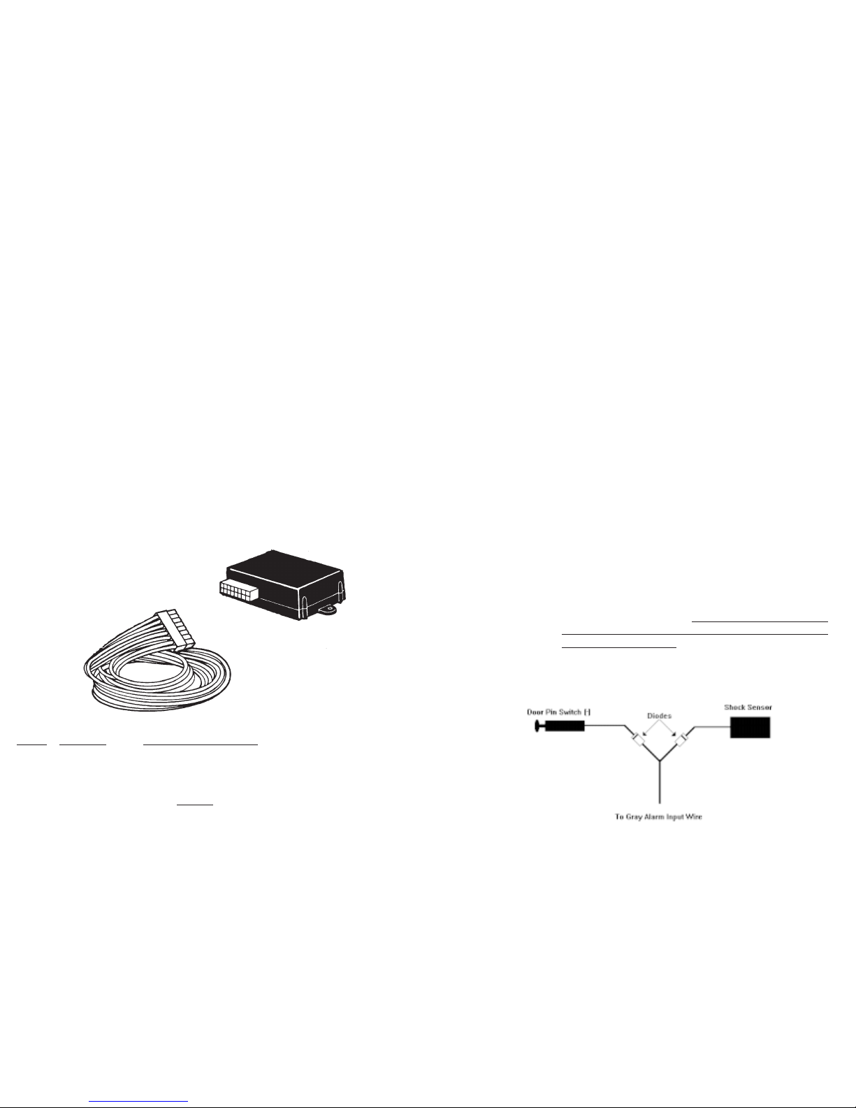
This system allows for a very quick installation using the generic harness (part
#27004)orwith'plug-in'vehiclespecificharnesses. Thetransmitterwhichcomes
withtheunitisalreadyprogrammedtothereceiverandincludesalonglifelithium
battery that will last many years.
CONTENTS: Model
20083 20084
25583 25584
Smart Entrytm Module YES YES
Transmitters (3 button) 1 1
Parts Baggie Yes Yes
Type of Lock and Unlock Outputs Transistor Relay
Contained in the baggie:
4 cable ties
2 "Protected by DesignTech" window stickers
ToolsRequired:
Set of screw drivers Drill and 1/2" drill bit for switch hole
Wire cutter and strippers Crimping tool
Soldering iron and solder Test / Volt meter
Smart Entrytm model 20084 has 2 built-in relays to control Lock and Unlock.
All other outputs are negative transistor outputs (-400mA) and require external
relays.
20083 / 20084 Page 3
1. Mounting and Connecting the module:
The information that follows shows the generic wire harness list. Custom har-
nesses designed to plug into specific vehicles are available and are separately
listed.
Screws or cable ties may be used for mounting the module in the driver's left kick
panel area. We recommend mounting after everything has been completed and
tested fully. Be sure to leave access to the LED and white push button on the side
of the case for programming.
Make sure that the white antenna wire is as straight as possible and not likely to
be touching any moving parts. Make sure not to let this white antenna wire touch
metal ground as this will severely impede transmitter range.
A description of each wire for the GENERIC Harness
(Model #27004) is as follows:
2. BLACK Chassis ground. (strip off 1/2" of insulation of the end of the
wire and screw to the metal frame in the kick panel area).
3. RED +12 volts constant such as the ignition power feed in the steer-
ing column area. (15 amp fuse must remain in-line).
STEP COLOR WIRE FUNCTION
Page 4 20083 / 20084
4. RED/BLACK This is the On/Off Control switch wire. This switch will al-
ready be connected to the harness. You will notice that one
side of the switch goes to the Red/Black wire and the other
side of the switch to Ground.
5. ORANGE Ignition input -- connect to an ignition wire which has +12
volt when key is in the ignition (normal running) position but
has no voltage when the key is out.
6. GREEN/WHITE Trunk or Auxillary output. For Trunk your vehicle must
have an electric trunk release. This is a negative transistor
output (-400mA) - you must use an external relay (not sup-
plied) when hooking up this wire. See Page 9 for a detailed
hook-up using a relay.
7. VIOLET Optional Starter Kill, Dome Light or Headlight transistor out-
put (-400mA). This wire must drive an external relay. See
Step 14 for details on setting these options.
8. BLUE Horn/Siren. This is a transistor output (-400 mA) which can
be used to drive an external relay which in turn can power a
horn or a siren. See programing options for changing this
output from horn to siren mode.
9. GRAY Optional alarm input. You can hook this wire to the vehicle's
door pin switch so that when the door is opened the alarm will
sound if the system is armed. This input is assuming negative
polarity. You must use a relay to switch the polarity on posi-
tive pin switch vehicles. You can also add additional alarm
sensor inputs -- such as a shock sensor -- to this wire. If you
add more than one input to this wire be sure to diode isolate
each input as shown here.

20083 / 20084 Page 5
10. ForthefollowingLock/Unlockwires --seetheseparateGREENSHEET
for vehicle wiring colors and locations as well as for instructions for
hook-up.
For Model 20083/25583: These are transistor outputs (-400mA) and must
drive relays. (Many Japanese vehicle can be driven directly from these nega-
tive transistor outputs).
WHITE/RED Lock transistor (-) output
WHITE/GREEN Not Used
YELLOW/RED Unlock transistor (-) output
YELLOW/GREEN Not Used
RED/WHITE Not Used
For Model 20084/25584: These are relay outputs.
WHITE/RED Lock Common relay output (Pin 30 of the on-board relay)
WHITE/GREEN Lock Normally Closed relay output (Pin 87a of the on-board
relay)
YELLOW/RED Unlock Common relay output (Pin 30 of the on-board re-
lay)
YELLOW/GREEN Unlock Normally Closed relay output (Pin 87a of the on-
board relay)
RED/WHITE Lock/Unlock relay polarity input -- must be hooked up.
(normally open, Pin 87 contact for both relays)
11. Plug the harness into the module at this time. Note that upon first power
up -- the red LED light on the module flashes once and gives you a 5 second
window to enter into the Transmitter Code Learning mode described toward the
end of the manual. After 5 seconds, the led flashes 4 short times to indicate the
end of transmitter code learning mode and the start of normal operation.
12. Mount the switch: Drill a 1/2" hole and mount the switch in a
convenient location for the user. Make sure the dot on the switch is facing
upward for correct orientation of up being 'On'.
Page 6 20083 / 20084
13. TRYING OUT THE UNIT:
Always keep one window rolled down to avoid locking yourself out of the vehicle.
Your transmitter has already been factory coded to the Smart Entrytm . (If it does not
trigger any of the following functions, and you have already checked your connections,
follow the steps for Transmitter Code Learning at the end of the manual.) Generally,
the transmitter button should be held down until the Smart Entrytm unit responds
with the desired feature.
Button 1: Hold for one second -- Lock and Arm (One chirp, if hooked up)
Button 2: Hold for Onesecond -- Car Locator (Brief Horn/Siren sound, if
hookedup)
Hold fortwo seconds -- Panic (45 second horn/alarm sound, if
hookedup)
Button 3: Hold for onesecond -- Unlock and Disarm (Two chirps, if
hookedup)
Hold for two seconds -- Pop the trunk
NOTE: If the alarm is sounding -- Button 2 held for 2 seconds will turn off the
alarm. Also, when you disarm the alarm -- it will give 4 chirps if the it
has alarmed since the last time it was armed.

20083 / 20084 Page 7
14. PROGRAMMING OPTIONS:
There are 4 options which can be set as described in the Programming Method section
following this section.
A. Horn-vs-Siren (Factory setting is Horn)
This product gives you the option of having a pulsed output for a car horn or a
constant output for a siren.
B. Lock Follow Ignition (Factory setting is "No Lock Follow Ignition")
This option will automatically lock the doors 2 seconds after the car is started,
and will automatically unlock the doors when the key is removed from the igni-
tion.
C. Passive vs Active Arming (Factory setting is Active Arming)
In the Active arming mode -- the alarm will not arm until you Lock the doors
with the Left button on the transmitter -- 1 chirp will be heard for arming.
Passive arming will arm and lock the vehicle 25 seconds after the key has been
removed from the ignition and all of the doors have been closed. You must still
disarm the system in both modes with the keychain transmitter's Left button -- 2
chirps will be heard for disarm. In passive arming the system will arm the door
pin switch, activate starter-kill, and Lock the doors 25 seconds after the ignition
is turned off AND the alarm has seen the last door close. Pushing the Left button
on the transmitter to control lock will override this passive feature. NOTE: The
doors will automatically Lock after the 25 seconds time.
D. Violet Wire Options: Starter Kill / Domelight / Headlight.
(Factory setting is Starter Kill). If you do not want Starter Kill, this VIOLET
wire can be set for two different functions -- Domelight or Headlights. In the
Dome light mode, the output comes on each time the door is unlocked with the
Right button -- and stays on for 25 seconds or until the ignition key is turned on.
In the Headlights mode the headlights will come on along with the horn/siren
during lock/unlock, panic and alarm. See Option 4 of the Programming Options
on the next page for setting these options.
Page 8 20083 / 20084
15. PROGRAMMING METHOD:
This section will set or reset any of the four options.
1) Turn the Control Switch (the toggle switch) OFF (down). (The switch has a
dot on the side which is the ON position).
2) Push the white button on the side of the case of the receiver and the red LED
will flash once letting you know you are in option 1. Push the white button
again to scroll to option 2 (the LED will flash twice) and again for option 3
(the LED will flash 3 times) and again for option 4 (4 flashes) -- then back
to option 1 again if necessary.
3) When you are at the option you want to change -- simply press the Left,
Middle or Right button on the transmitter to choose the function you want.
After a few seconds of holding the transmitter button down -- the red LED
on the receiver will come on signifying acceptance of new option -- then you
can release the transmitter button and push the white button again to scroll
to the next option or wait 5 seconds for this routine to exit out.
Transmitter Button to be pressed
Left Middle Right
Option 1: Lock Follow Ignition
“No Lock Follow Ignition” X
“Lock Follow Ignition” X
Option 2 Passive vs Active Arming
Active X
Passive X
Option 3: Horn vs Siren
Horn X
Siren X
Option 4: Function of Violet Wire
Starter Kill X
Dome Light X
Headlights X
20083 / 20084 Page 9
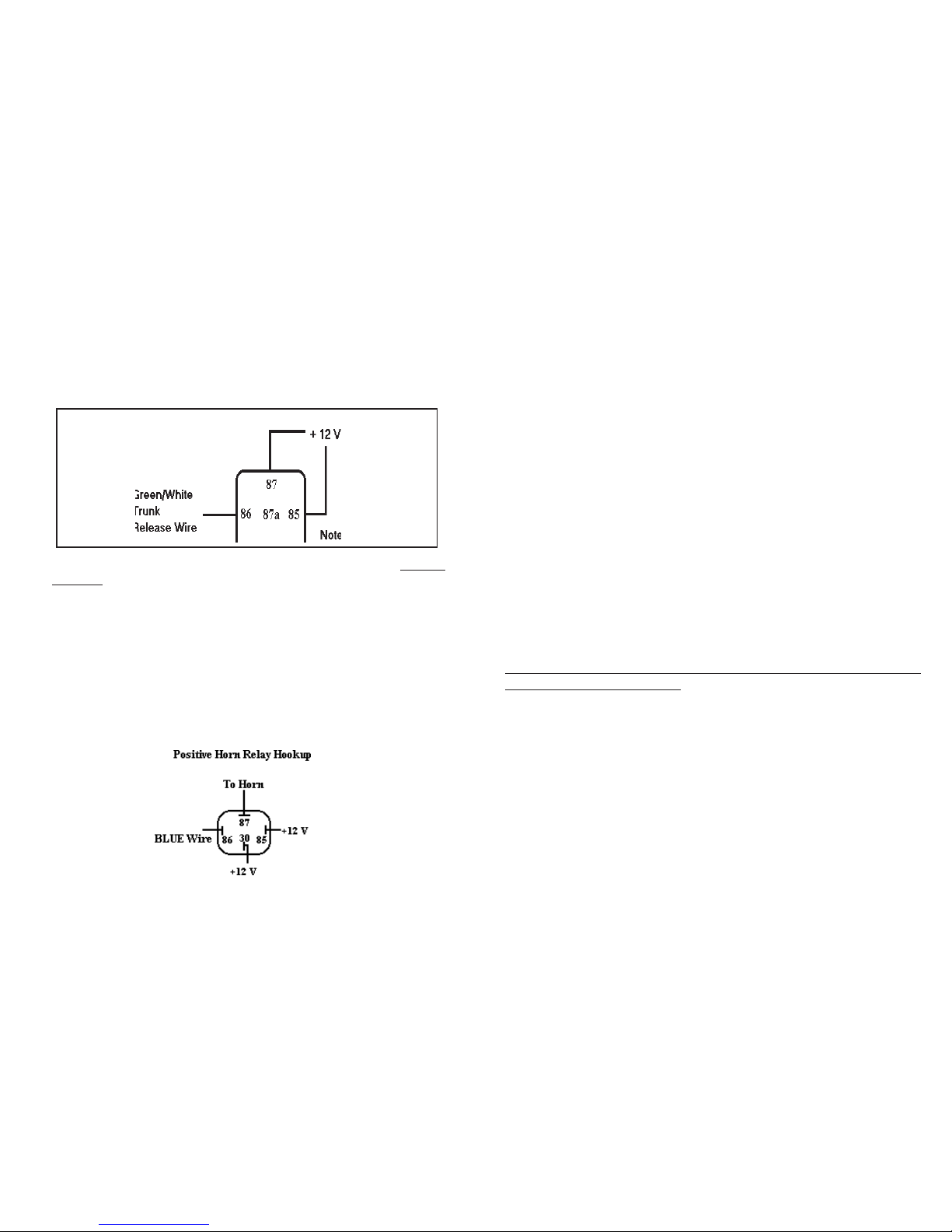
16. Example of optional Trunk hookup using an external relay:
Take a relay with 10 amp or higher capacity and a 12 volt coil. Locate the
push button for the trunk (usually in the glove compartment). You will
noticetwowiresbehindthis push button switch. Connect the Smart Entry's
Green/White Trunk wire to one side of the relay coil and constant +12
volts to the other side of the coil. Both the Common and Normally Open
contacts of the relay go to the push button switch:
If you are using one of the automotive industry standard relays like the Bosch 30
amp relay -- the connections would be as follows:
Pin 85 (Positive side of relay's coil) +12 volts constant
Pin 86 (Negative side of relay's coil) Green/White wire
Pin 30 (Relay's common contact) One side of the trunk push button wire.
Pin 87 (Relay's normally closed contact) The other side of the trunk
push button wire.
Example of Horn hookup using an external relay:
Take a relay with 10 amp or higher capacity and a 12 volt coil. This example
shows a Bosch 30 Amp relay being used.
Page 10 20083 / 20084
17. Transmitter Code Learning: Your Smart Entry module comes
factory coded to one of 16 million different codes and is already programmed. If
you unit does not respond to your transmitter in any way after checking the con-
nections, or you want to have additional transmitters (up to 4) to trigger your
Smart Entry module -- follow the following directions:
1. Disconnect power for 5 seconds. Re-apply power.
2. Within 5 seconds, push the white button on the side of the Smart Entry
(the red LED will flash twice) then push and hold the left button on the
transmitter for 5 seconds until the red LEDon the receiver comes on -
- stop pushing transmitter button.
3. If you have a 2nd transmitter, within 5 seconds push the left button for
a few seconds until the red led on the receiver comes on. Release
transmitter button. Repeat for up to 4 total transmitters.
4. Wait 5 seconds for receiver to exit out of code learning mode -- the red
led on the receiver flashes 4 times.
Note: Teaching the module a new transmitter code will erase all previ-
ously learned codes -- so all transmitters must be taught.
Ifyouhavelost your transmitter and the alarmisarmed,itcanbeturned off
as follows using the valet switch:
1. Insert your key into the vehicle ignition and turn to the "run" position.
2. Toggle the valet switch four times off and on and the alarm will disarm.
For any technical assistance regarding this product you may call DesignTech on our
toll-free telephone number - (800) 337-4468.

20083 / 20084 Page 11
7955 Cameron Brown Court; Springfield, Virginia 22153 USA
Tel: 703-866-2000 ; Fax: 703-866-2001
OTHER ACCESSORIES
A. Extra transmitters for more than one user in the family. Up to four transmitters can be
used with each Smart Entrytm.
B. Garage Door Receiver Unit will allow Your Smart Entrytm transmitter to operate an
electric garage unit.
C. You can remotely control your vehicle with our AutoCommand model 20022.
These products are available through your dealer or directly from DesignTech :
3 button transmitter 20061 $49.95
AutoCommand remote starter 20022 $149.95
30 amp relay 20043 $9.95
Siren 20400 $49.95
Shock Sensor 20610 $49.95
Transmitter batteries 20059 $7.95
Universal Garage Door Module 30021 $49.95
All prices are in US Dollars and include shipping and handling.
Page 12 20083 / 20084
LIMITEDWARRANTY
DesignTech International,Inc. Warrants tothe originalconsumer/purchaser that this product shall be free
ofdefects in material andworkmanship under normal use and circumstances for a periodof two (2) years
from the date of original purchase for use. When the original consumer/purchaser returns the product to
DesignTech International Inc., 7955 Cameron Brown Court, Springfield, Virginia 22153 within the war-
ranty period, and if the product is defective DesignTech International, Inc. will at its option repair or
replacesuch.
This warranty shall constitute the sole liability of DesignTech International, Inc. concerning the product.
DesignTech International, Inc. expressly disclaims all otherwarranties INCLUDING, WITHOUT LIMI-
TATION, THE WARRANTIES OF MERCHANT ABILITY AND FITNESS FOR A PARTICULAR
PURPOSE. NO PERSON, FIRM , OR CORPORATION IS AUTHORIZED TO ASSUME FOR
DESIGNTECH INTERNATIONAL, INC. ANY OTHER LIABILITY IN CONNECTION WITH THE
SALE AND USE OF THE PRODUCT. DesignTech International, Inc. and agents and distributors will
bear no liability whatsoever for incidental or consequential damages or charges of any kind.
Some states do not allow the exclusion or limitation of incidental or consequential damages, so the above
disclaimer regarding incidental or consequential damages may not apply to you.
This warranty shall be effective only if the registration card is fully completed and mailed with proof of
purchase to: DesignTech International, Inc., 7955 Cameron Brown Court, Springfield, Virginia 22153
within ten (10) days after date of purchase.
This warranty is void if the product or has been damaged or tampered with or if the product or any such
parts have been opened. In all cases of damage during shipment, a claim must be filed with the shipping
carrier and not with DesignTech International, Inc.
Thiswarranty gives you specificlegal rights; you may also have other rights whichvary from state to state.
OUTOF WARRANTY REPAIRS
DesignTech International, Inc. will at its option either (1) replace this product with a functionally similar
(butnot necessarily visually identical) refurbishedproduct or (2) repair the original product and return it to
theoriginal consumer/purchaser C.O.D. covering all reasonable repair or replacement chargesif the prod-
uct is returned prepaid to DesignTech International, Inc., 7955 Cameron Brown Court, Springfield, VIR-
GINIA 22153, after the two year warranty period has expired.
__________________________________________________________________________
This registration card must be returned within ten (10) days of purchase.
NAME__________________________________________________User's Age_________
ADDRESS________________________________________________________________
________________________________________________________________________
City State Zip
PLACE OF PURCHASE_________________________DATE OF PURHASE____________
Product Purchased: _____model 20083/25583; ______model 20084/25584
Purchasedfor : __________YOURSELF _________SPOUSE
__________OTHER FAMILY MEMBER _________FRIEND
Where did you learn about this product?__________________________________________
Vehicle Make:__________________Vehicle Model:________________Year:____________
___________Please send me FREE information on other innovative DesignTech products.
DesignTech International, Inc.
7955 Cameron Brown Court, Springfield, Virginia 22153
Tel: (703) 866-2000 Fax: (703)866-2001
Table of contents
Other DesignTech Security System manuals


