CEBEK AL-10 User manual

AL-10
Alarm station
Station for alarm system. Device for the control and processing of the shot from Input, output, corresponding timings, out for
telephone indicators, input against manipulation, and optocoupled Input relays detection sensors.
It Includes relay, acoustic indicator and status leds for the count down of the activation/deactivation and shot.
TECHNICALCHARACTERISTICS
Power supply:12/24 V D.C.
Maximum consumption:80 mA.
Relay of a switched circuit:250 V./5A. maximum.
Alarm shot, Relay activation: 2 min.(Repeating the cycle up to the alarm disconnection).
Alarm activation (it can be selected): by Closing contacts or high level, (5 V.D.C.)./ Supplying the module
Alarm deactivation: Closing contacts or high level, (5 V.D.C.).
Shot alarm input: Optocoupled, external signal at high level, 12 V.D.C. a
Input against manipulation: Closing of contacts or high level, (5 V.D.C.).
Min./Max timing for input and output times: 2 scales can be selected (0 to 24 sec.), (24 to 50 sec.).
Shot output for auxiliary circuits: NPN open collector output, (100 mA. max.).
Indicators for available activation time, output and indicator of shot alarm:leds 3 mm.
Net weight:65 gr..
Length x Width x Deep:87,5 x 72 x 30 mm.
Operating temperature:-25 ºC up to +55 ºC.
Rules: In accordance with 89/336/CEE Electromagnetic compatibility rule and its 32/31/CEE and 93/68/CEE modifications. RoHS free.
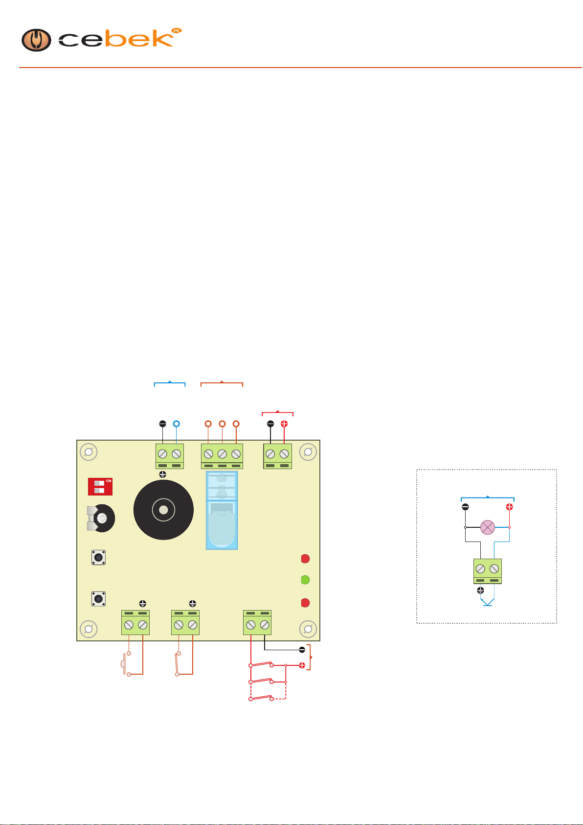
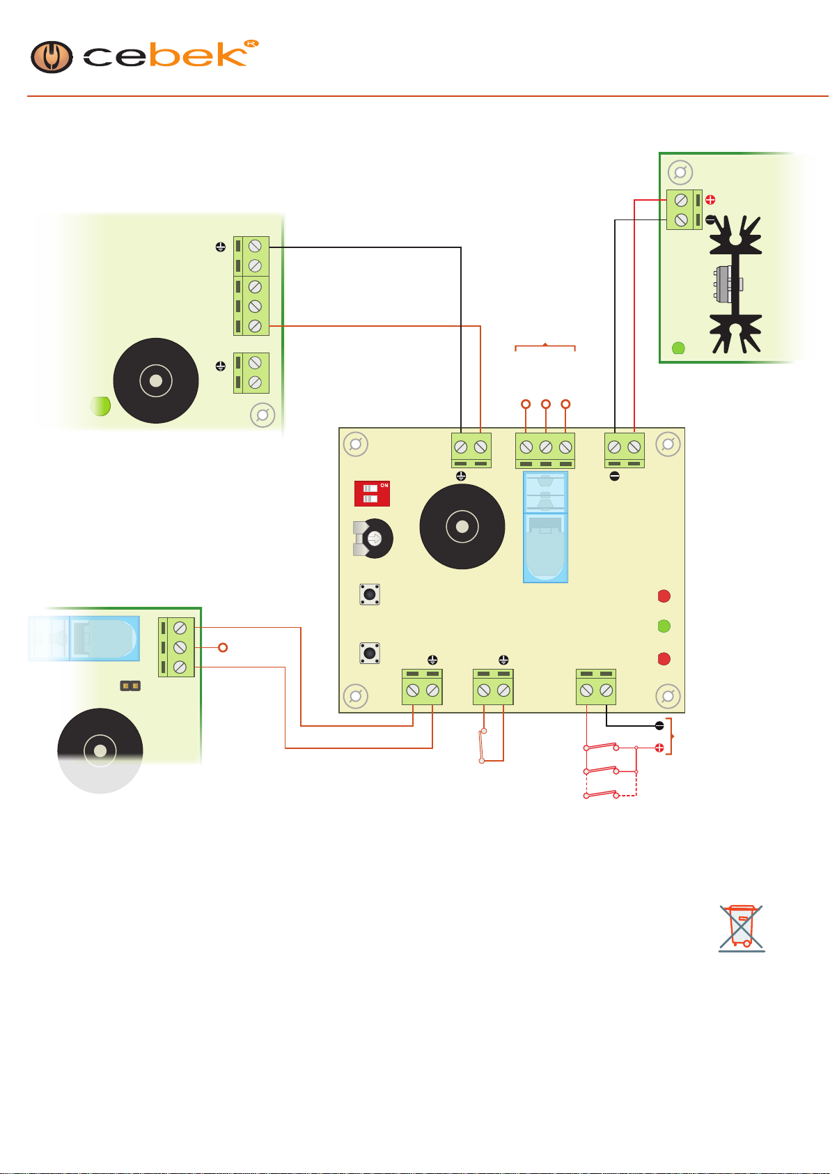
INSTALLATION
Powersupply.
The connexion has to be done on the “Power” input. Respecting the polarity, the AL-1 circuit requires a 12 VDC power supply correctly filtered. We
recommend you to use a short circuit power supply with low ripple level, as our FE-103 or FE-503 power supplies, which have been developed to
perfectly answer to the circuit needs. Do never use transformer or rectifier to avoid to damage the circuit.
Note: Install a fuse and a switch has it is indicated on the schedule. Both are necessary for the module’s protection as well as for your own safety, as
it is required by the “CE” regulations. Consult the corresponding power supply’s instruction manual.
Control inputs.
The module has 3 inputs. The length of the cable used in for their connexion has to be as short as possible. If the distance is superior to 50 cm, it will
be necessary to use shielded cable, connecting the braid to the corresponding terminal indicated with the ground symbol. In any case, the maximum
length will be to 2m.
Activation of Start and Box inputs. The activation of these two inputs is done closing the corresponding terminal with the common negative terminal
indicated with the ground symbol. The activation can be also done through an external voltage signal. In such case, the signal have to be 5. DC.
perfectly stabilized, with the negative connected to the circuit’s common negative, terminal with the ground symbol. The activation will be done if the
signal is equal to 0 V.
Activation of the “Alarm-In” shot input. The activation and corresponding alarm shot, (if it is not firstly deactivated), will be done when the input
receives a 12 V.D.C signal. It does not allow the activation closing both terminals, but an external 12 V.D.C signal connected according to the polarity
indicated on the circuit.
The input Against Manipulating is activated when released the union of its two terminals, (Box and ground), or via external signal of 5 VDC, when this
is like to 5 V. Its operation for a switch that controls the closure of the carrier of the alarm, if it is opened without disconnecting the alarm previously,
the switch will release the two contacts for the Box input fire alarm, regardless of the expected time of entry.
Salida O_SiG.
The "O_Sig" output is activated when the relay of the circuit do it, that mean when the alarm is activated, supplying to the output a NPN transistor
signal to opened collector, destined to the activation (for instance), of Cebek telephone dialling circuits, like DA-08.
When it has happened an intrusion without deactivation code, the relay and the "O_Sig" output are activated. In the drawing, there is a connexion of
this output with a dialling circuit to warn about the intrusion, calling to the pre-assigned number, (DA-08 module).
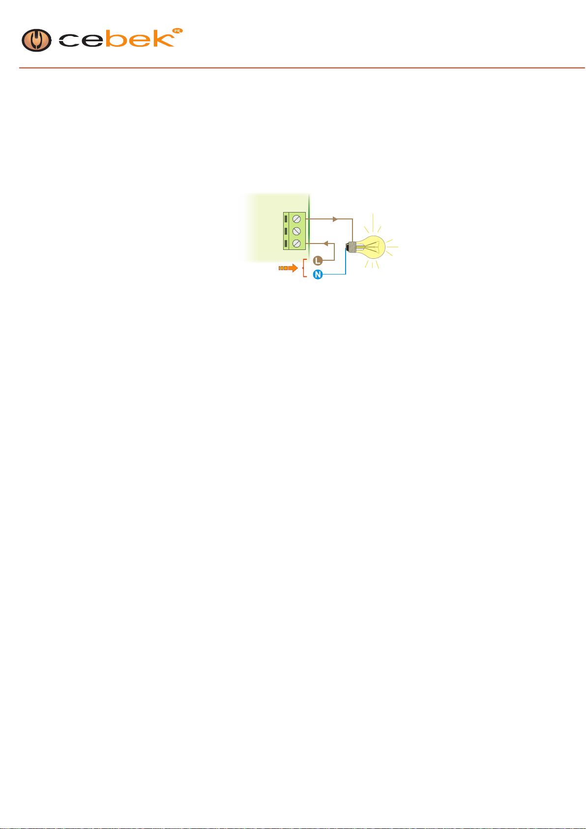
Relay Connexion. To control sirens orotheralarm indicators.
The relay connection does not have to be contemplated like an output, it does not supply voltage. Electrically insulated from the rest of the
circuit, its function is to open or to close its contacts to allow or to interrupt the cross of an electrical signal, like a standard switch with a bulb.
The relay has three terminals: Common, Normally opened in rest (NOT), and Normally closed in rest, (NC).
You have to directly connected one of both load supply cables to the same one, the other one has to be inserted through contacts of the relays,
typically between the Common and NO, as it is specified in the fig 1, internally the relay will cut or valid the electric flux of the cable.
1/4
rev. 3708
Connection of the load in A.C.Connection of the load in D.C.
Fig 1. How to connect the load
Load connexion. Load connexion.
Normally closed, (Nc)
Normally Open, (No)
Common
Load,
Device
Normally closed, (Nc)
Normally Open, (No)
Common
Load,
Device

AL-10
Alarm station
INSTALLATION , (continued).
Considerations of the relay.
Specially with inductive loads, a relay output can produce a fluctuation, flashing, etc,.. or an incorrect operating mode. In such case, you have to
install an anti-spark circuit between the two relay contacts used in the connexion, that will assure the absorption the current peak generated by the
mentioned problem. See the fig 2.
If the load connected to the relay of the circuit is supplied at 230 V. you have to apply a 100nF/400 V type X2 capacitor and a 47 ohms ½ W resistor.
If the load is supplied at 12 or 24 V. D.C., the installation will only require a X2 capacitor, without the resistor. If necessary, you could use different
values, from 10 nF till 47 nF, but always with capacitors type X2, until the fluctuation disappears.
Considerations on the installation.
Preferably, you have to install the circuit into a box, enclosure or rack correctly ventilated.
The device does not be installed in places with great humidity and possibility of condensation, very high temperatures, or in contact with líquids.
You also have to avoid the contact between the circuit and metallic objects like bracelets, chains, etc.
OPERATING MODE
Operating modes.
There are two operating modes for this module, the Programming mode where alarm times are configured, and the Operative mode where the alarm
acts or is in rest.
When the alarm is activated, the output time is the interval that the alarm is “waiting for” sensors signals to be activated if necessary. It is the
maximum time to leave the place without being detected.
The input time is the margin that the alarm offers to be deactivated before its activation. It is the maximum time, once detected to use the code, the
key or the deactivation switch.
Programming.
It is only possible to reach the programming mode if the alarm is not activated. (green LED light on).
During the programming the output time and the input time can be adjusted, between 0 and 50 seconds.
Time selection is done adjusting the TIME variable resistor placed on the circuit. Being O sec. the minimum and 25 sec. the maximum if the DIP 1 is
placed in Off. If the DIP 1 is placed in On, the variable resistor can be adjusted between 24 and 50 seconds.
Programming process.
The access to the programming mode, you have to maintain pressed Enter during a minimum of 3 seconds, then automatically the module will
generate a brief acoustic signal and it will be located in the Output time.
Output time (Green LED blinking).
To store the position and time of the variable resistor, a pulsation must be done in Enter. The circuit will emit a long acoustic signal indicating the
attainment of the operation and will leave the Programming mode.
To make no changes in the output time and to pass to the input time, you have to do a brief pulsation in Select
Input time (red LED "On" blinking)
As it was previously indicated, to accede to input time repeating the process to accede to programming mode and pressing on Select. The position-
ing in the input time will be correct if the red LED is blinking.
As for the output time, a pulsation on Enter will store the position and time assigned to the Timer variable resistor. The circuit will store in the input
time the new registry and will emit a long acoustic signal, if the modification has been correctly done, leaving the programming mode
Select, will switch the programming between input time and output time. If Enter is not pressed, there is no change in the corresponding time.
If there is any pulsation on Enter or Select in an interval of 20 seconds, automatically the circuit will leave the stored Programming mode.
Registries stored in the input time and output time will not be eliminated when the module is not supplied; they can only be modified with a new time
allocation through the programming mode.
Operative mode
Activation/ Deactivation
Initially the alarm is unworkable, in rest, (green LED light on). Activating the Start input, the count down of the output time is activated. The acoustic
indicator will generate several followed tones, increasing their speed as the end of the timing.
Finally, the alarm will be activated, (red LED light on) and waiting for any sensor signal.
Deactivation and return to the unworkable state is done when the start input is activated. The activation and the return to the unworkable state is
done when you press again on the Start input.
2/4
rev. 3708
Fig 2. Anti-fluctuations filter of the relay.
Load connexion.
Normally closed, (Nc)
Normally Open, (No)
Common
Load,
Device

OPERATING MODE, (continued).
Activation/ Deactivation
The alternative between On and Off, is done each time you press Start, allowing access controllers using the PIN code (like our DA-03 or other
access controllers), to activate or deactivate the alarm each time you insert a code, an access card , etc...
Alternatively to the activation/deactivation through the start input, the circuit can be configured to automatically connect the alarm when it is supplied.
This function is predicted for applications when there is a loss of electrical fluid, and for higher security the alarm must remain activated.
Through DIP 2 you can configures this function. DIP 2 on Off does not allow the automatic activation. DIP 2 on ON allows automatic activation when
it is supplied.
Alarm activation. Sensor.
When the module detects the activation of the Box input, it is automatically activated.
When the module detects the activation of the Alr_In input, the input timing starts. If before its end, the alarm is not deactivated, there will be a shot.
The object of the Box input is to install a sensor against the box opening where the alarm is placed, avoiding the forced deactivation after a non
authorized entrance. For this reason its shot is immediate without any possibility to timer it.
The Alr_In input must be connected to the different sensors which are centralized in the alarm. These sensors have to be connected in parallel, or to
be placed on a concentrator circuit that transmits a single signal to the alarm. The sensors signal levels or commutation type must correspond to the
described ones in the section : Installation.
If the shot is done, the relay connexion time will be 2 minutes. (This time cannot be modified). When this time is finished, if the Alr_In input or the Box
input are still active, the module will continue during 2 minutes more, continuously until the alarm will be deactivated or the shot condition in Alr_In or
Box disappears.
3/4
rev. 3708
AL-10 CONNECTION
Outp ut Wiring Ma p O_Sig
AL-10
Alarm station
1 2
AL-10
On
Select
Time
Acoustic indicator
Buzzer
Set
O_Sig
Start
Box
Alr_In
Sensor Nc
Activation/Desactivation
No, (push button normally open) Sensor Nc
Sensor Nc
Sensor
Enclosure / Rack
Nc, (normally closed)
Relay
Power
Time
Auto
Enter
Off
Alr
Oc
BoxSt
min.
max.
+12 0
Relay
Sensor’s Supply
Power Supply
(+12 V.D.C.)
NPN Output (BC337)
Open Collector
12 V.D.C.
Common
Emitter
Collector
Nc
No
O_Sig
Output NPN (Open Collector)
Load Power Supply
Load
BC337

INFORMATION REGARDING the PROTECTION of the ENVIRONMENT
When this product is no longer in use, it cannot be deposited next to the normal domestic residuals, it is necessary to take it
to a point of selective collection for electrical and electronic apparatuses recycling. A symbol on the product, instructions
manuals or the packing indicates it. Materials are recyclable as they are marked. If you practice the reuse, the recycling or
another form of use of old apparatuses, you are making an important contribution toward the protection of the environment.
Please consult to your city council which can inform you bout the nearest and appropriate drain from your home.
DO NOTFORGET/ WARRANTY
This component has to be used by professionals, or end-user with enough knowing and/or a determinate technical level, allowing him to develop
himself its required projects or applications. If it is used for didactic purpose we strongly suggest to use and to assemble it under the teacher
supervision. Cebek does not offer additional explanations, technical assistance nor alternative didactic support to the reflected one in the present
instructions manual. The guarantee of this one product is exclusively prescribed to pieces supplied in this kit, to damage or wrong operating mode
not provoked by inadequate or wrong handling form the user. In such case you have to contact with our technical department, Electronic
mail:[email protected]/fax +34 93 432 29 95/tel. +34 93.331.12.49. The Cebek products have 3 years of guarantee from the date of purchase. We
can bring technical modifications without previous information. We did not assume any responsibility by errors of technical modification. The
instruction manual of this product corresponds to the transcription of the documentation supplied by the manufacturer. For more information, please
consult our web site: www.cebek.com where you can also find more products.
4/4
rev. 3708
AL-10
Alarm station
AL-10 CONNECTION
WEEE
1 2
AL-10
FE-103
DA-08
DA-03
On
Select
Time
Acoustic indicator,
(Buzzer)
Set
O_Sig
Start
Box
Alr_In
Sensor Nc
Sensor Nc
Sensor Nc
Sensor
Enclosure / Rack
Nc, (normally closed)
Relay
Power
Time
Auto
Enter
Off
Alr
Led
Oc
Prg
BoxSt
JP2
min.
max.
+12
+12 0
Relay
Sensors’supply
Power Supply AL-10. (12 V.D.C.)
connection to telephone transmitter
Activation by PIN code 12 V.D.C.
Common
Nc
No
Common
Nc
No
Rec
AL1
AL2
AL3
AL4
This manual suits for next models
1
Table of contents