DESSALATOR PRO COMPACT D90 Use and care manual

PRO COMPACT & CAD D90 to D200 v2.4 (03/21)
PRO COMPACT & CAD – D90 to D200
90 to 200 liters/hour – 230 (or 400V)
ASSEMBLY AND USER MANUAL
Dessalator®
ZI des 3 Moulins
282 rue des Cistes
06600 Antibes, France
www.dessalator.com
PRO CAD
PRO COMPACT

PRO COMPACT & CAD D90 to D200 v2.4 Page 2
Table of Contents
Copyright / Disclaimer ............................................................................................................. 3
List of Components .................................................................................................................. 4
Assembly ................................................................................................................................. 7
1) List of supplies necessary for assembly .................................................................... 7
2) Seawater inlet ............................................................................................................ 8
3) Motor/Pump Block .................................................................................................... 10
4) Electric connections ................................................................................................. 11
5) Membrane Block ...................................................................................................... 11
6) Control panel ............................................................................................................ 12
7) Mini Remote Control (optional) ................................................................................ 14
Start-Up ................................................................................................................................. 15
1) Precautions before start-up ...................................................................................... 15
2) Starting-up the watermaker ...................................................................................... 16
3) Stopping the watermaker: without rinsing of the membranes .................................. 18
4) Stopping the watermaker: with automatic rinsing of the membranes ...................... 20
5) Using the Mini Remote Control (optional) ................................................................ 22
Operation ............................................................................................................................... 23
Maintenance .......................................................................................................................... 24
1) Membranes maintenance ........................................................................................ 24
2) Rinsing frequency of the membranes ...................................................................... 24
3) Sterilizing the membranes ....................................................................................... 25
4) High-pressure pump ................................................................................................ 26
Spare Parts ............................................................................................................................ 26
Appendix A1: How do watermakers work? ............................................................................ 27
Appendix A2: Mounting of the DESSALATOR® high-pressure nozzles ............................... 28
Appendix A3: Manual Rinsing Procedure .............................................................................. 29
Appendix A4: Instructions for the Sterilizing Cartridge .......................................................... 30
Appendix A5: Troubleshooting .............................................................................................. 31
Appendix A6: Guide of the Indicator Lights of the Mini Remote Control ............................... 32
Appendix A7: Circuit diagram of the electronic board ........................................................... 33
Appendix A8: Schematic drawing COMPACT version .......................................................... 34
Appendix A8: Schematic drawing CAD version ..................................................................... 35

PRO COMPACT & CAD D90 to D200 v2.4 Page 3
Copyright / Disclaimer
Dessalator®
ZI des 3 Moulins, 282 rue des Cistes
Bâtiment Euro 92
06600 Antibes, France
www.dessalator.com
+33 4 93 95 04 55

PRO COMPACT & CAD D90 to D200 v2.4 Page 4
List of Components
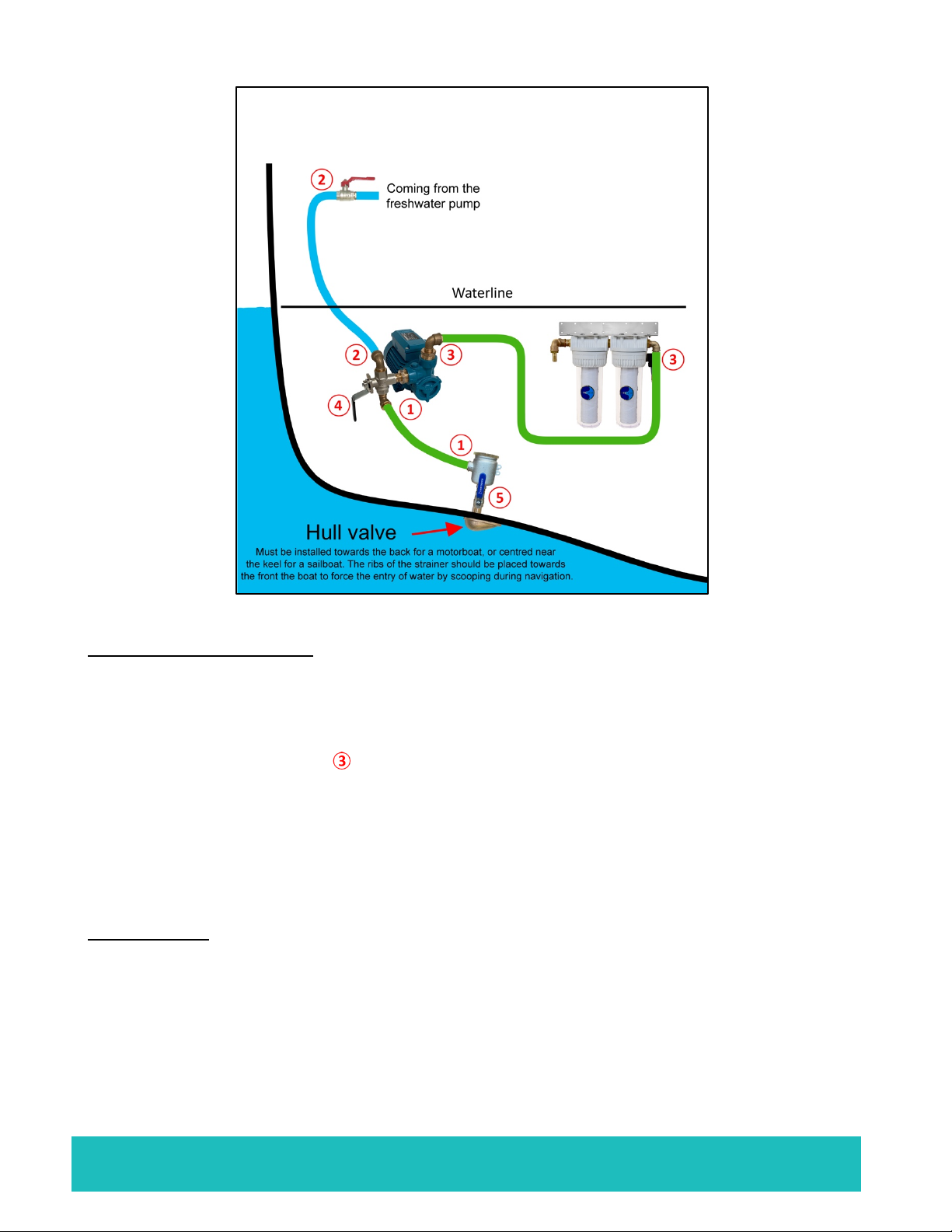
Hull Valve
Ø Must be placed as low as possible in the boat so as to avoid drawing in any
air
Ø Must be installed towards the back for a motorboat, or centered near the
keel for a sailboat. The ribs of the strainer should be placed towards the
front the boat to force the entry of water by scooping during navigation.
Ø The strainer of the hull valve helps stop large particles at the entrance of the
system.
Ø The basket filter is attached directly to the valve (photo opposite).
Prefilter
Ø Must be placed as close as possible to the hull valve and, if
possible, beneath the waterline to ensure a better yield/output.
Ø The first 25 micron cartridge does the pre-filtration, then the
second 5 micron cartridge brings a finer filtration.
Ø Comes with a tool for screwing / unscrewing the tank.
Ø Comes equipped with a solenoid valve for automated rinsing
of the fresh water system.
Seawater pre-pump
Ø The pre-pump is equipped with a 3-way valve (for manual
rinsing of the fresh water system).
Ø It must be placed as low as possible in the boat and be easily
accessible.
Ø The pressurized fresh water must be connected to the three-
way valve to facilitate manual rinsing and sterilization of the
watermaker; see the layout diagram at the start of the user
manual.
Tip: Do not forget to place 2 stainless steel collars at each joint
DO NOT PLACE THE PUMP WHERE THERE IS A RISK OF WATER SPRAYS

PRO COMPACT & CAD D90 to D200 v2.4 Page 5
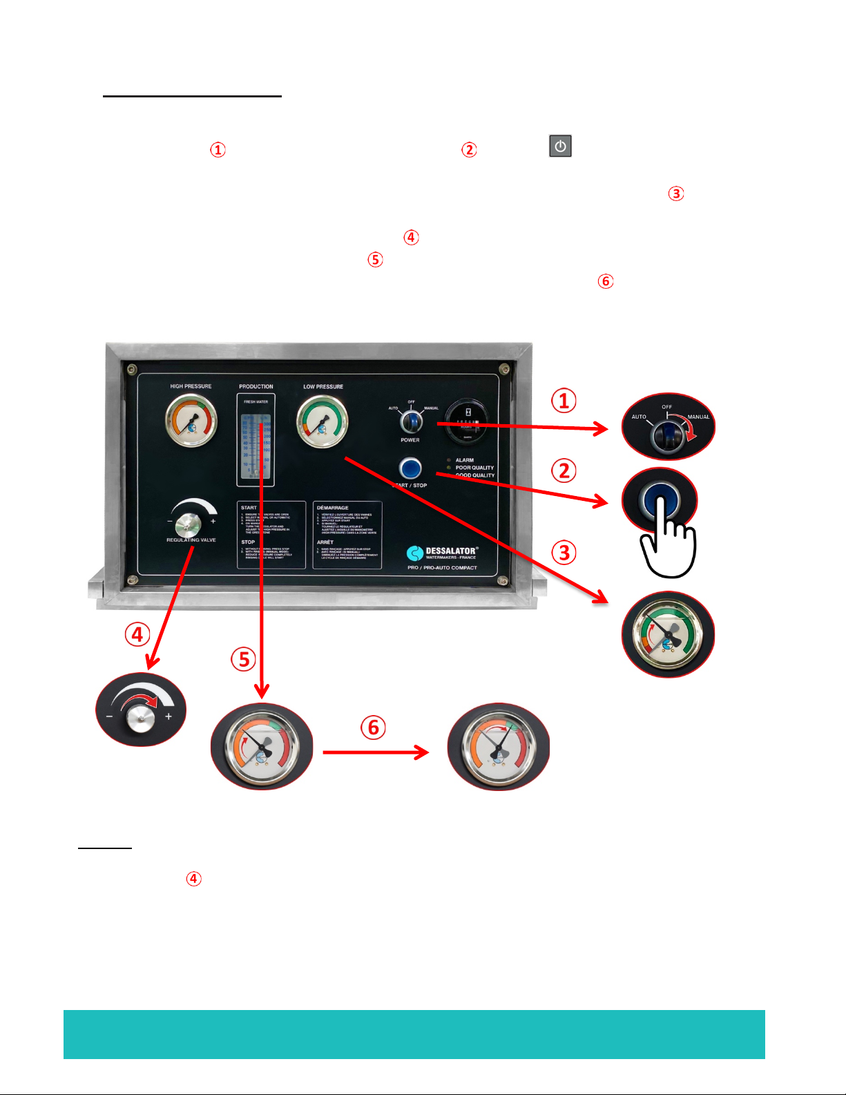
Front Control Panel
The control panel is separate from the engine (for the CAD version) and incorporated into the
frame (for the COMPACT version). It allows you to control the watermaker and is made up of
the following elements:
Ø A high-pressure manometer
Ø A flowmeter
Ø A start switch
Ø A Manual or Automatic mode selection switch (optional)
Ø A dial for pressure adjustment
Ø An operating hours counter
Ø Three indicator lights for control
CAD version
COMPACT version

PRO COMPACT & CAD D90 to D200 v2.4 Page 6
Motor Block
Ø The HP motor block can push seawater out to 60-65 Bars.
Ø Composed of the 230 or 400 Volts motor.
Ø Must be installed in a ventilated space.
Ø The motor block is separate from the control panel for the CAD version or is incorporated
in a frame which contains the control panel for the COMPACT version.
CAD version COMPACT version
Membrane Block
The number of membranes depends on the desired production flow: 90 to 200 liters/hour
1 membrane for a production of 90 liters of
water per hour (1200x100x120mm).
2 membranes for a production of 160 liters of
water per hour (1200x190x120mm).
3 membranes for a production of 200 liters of
water per hour (1200x270x120mm).

PRO COMPACT & CAD D90 to D200 v2.4 Page 7
Piping (supplied by Dessalator®)
Ø High-pressure piping from the pump to the membranes and from the membranes to
the control panel. An 8-meter pipe is provided, it should be cut into two parts. The
length of each part is to be determined according to the distance of the different
elements.
Ø 4 special DESSALATOR® fittings* for high-pressure piping (see assembly procedure
in Appendix A2).
§ * Including one 90° elbow fitting for the back of the control panel, which can
swivel 360°.
Ø Fresh water production piping going from the outlet of the membrane block to the
dashboard (6 meters long).
Assembly
1) List of supplies necessary for assembly
Ø Screws (self-tapping and more).
Ø Stainless steel ties, Ø 8-16mm and Ø 12-22mm.
Ø ‘Electrician’ plastic ties.
Ø Loctite 542 liquid or Loctite 577 paste.
Ø Polyurethane sealant, Sicaflex or equivalent.
Ø Corrugated sheath for electric cables and high-pressure tubes.
Ø Braided-core flexible hose, Ø 12mm, Ø 15mm and Ø 19mm inner diameter Tricoclair
and 3mm thick.
Ø Various tools (drills, saws, Ø 271mm hole saws, etc.).

PRO COMPACT & CAD D90 to D200 v2.4 Page 8
2) Seawater inlet
Seawater inlet valve
Ø The strainer should be placed as low as possible beneath the waterline so that it does
not draw in any air. It should be placed far from the discards.
Ø Pierce the hull with a Ø 27mm hole saw.
Ø The streaks of the strainer must be placed towards the front of the boat to allow the
water to naturally enter by scooping during navigation.
Ø Seal the junction with the hull properly using polyurethane sealant or Sicaflex. Do not
forget to paint the submerged part with special underwater paint.
Ø The hull valve must remain accessible for maintenance operations.
Ø Seal the valve/strainer and valve/hose connections with Loctite 577.
Seawater pre-pump
Ø The pre-pump must also be installed below the waterline for better production and
must be easy to access.
Ø The pre-pump is equipped (at its suction) with a 3-way valve
Ø On the 3-way valve: for the seawater suction of the pre-pump (on the seawater
inlet valve side), the connection must be made with Tricoclair type piping with an
inside diameter of Ø 19 mm . And with Tricoclair piping with an inside diameter
of Ø 15 mm for the other side of the 3-way valve (rinsing side).
Ø The connection for rinsing with fresh water must be made with the water from
the pressurized fresh water group circuit.
Ø The discharge from the pre-pump to the pre-filter block must be made with
Tricoclair type piping with an inside Ø 15 mm.
Ø The valve handle must be switched to the seawater position (see Appendix 3
for the 3 positions of the 3-way valve).
Ø An optional fixing bracket is available to fix the pre-pump to a vertical wall.
➥
Note : For manual rinsing, switch the valve handle to the fresh water position (see below
for the 3 positions of the valve) and follow the instructions in Appendix A3.
PRO COMPACT & CAD D90 to D200 v2.4 Page 9
Cartridge prefilter block
Ø The prefilter must also be installed beneath the waterline to ensure a better
yield/output. It must be easy to access.
Ø The fixing bracket is reversible to allow you to adjust the installation height.
Ø For the inlet and outlet , piping connections must be made with Tricoflex Ø 15 mm
(inside diameter). Do not forget to fasten 2 stainless steel collars on each fitting.
Ø Allow a minimum of 3 cm below the filter body for the clearance of the tank when
opening it. A screw is provided for screwing / unscrewing it.
Ø A solenoid valve is mounted behind the prefilter for automatic rinsing.
Connections
Ø Fasten two stainless steel collars on each connection, with the clamping heads
positioned opposite one another.
Ø Connection can be made under a sink, a washbasin or on the path of the pressurized
cold water piping.
Ø If the pipes are to pass through walls or be in contact with sharp corners, provide
protection against wear and friction by inserting them into a sheath or pipe of greater
diameter.
PRO COMPACT & CAD D90 to D200 v2.4 Page 10
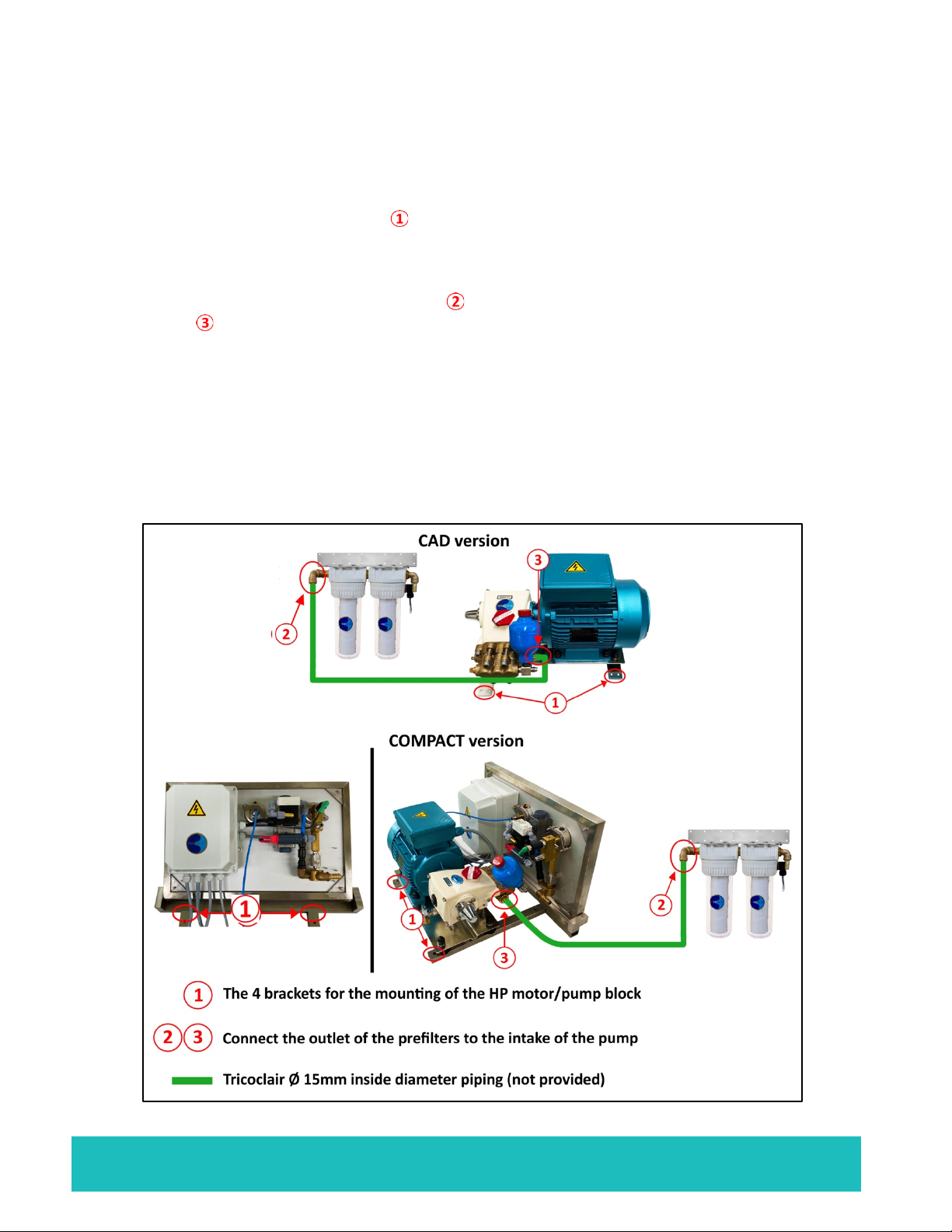
3) Motor Block
Ø To ensure optimal production, the assembly of the high-pressure motor block must be
completed in a horizontal position and in an area protected from water sprays.
Ø Use the 2 stainless steel legs under the 2 motors to fix the motor block. Leave a
few centimetres of wiggle room around it.
Ø Provide sufficient airflow for the ventilation of the motors.
Ø The connection of the prefilter outlet to the inlet of the pump on the suction-side
pump should be done using Tricoflex piping Ø 15mm (inside diameter) and 2
stainless steel collars at each connection.
Ø The connection of the pump's high-pressure head to the membrane inlet (red mark)
should be done using a high-pressure hose that is cut to size (follow closely the
assembly instructions in Appendix A2).
Ø Put a little liquid Loctite 542 or threadlock on the male and female cones before each
connection.

PRO COMPACT & CAD D90 to D200 v2.4 Page 11
4) Electric connections
Electrical connection of the 230 Volts (or 400 Volts) motor:
Electrical connections of the 230 Volt pre-pump:
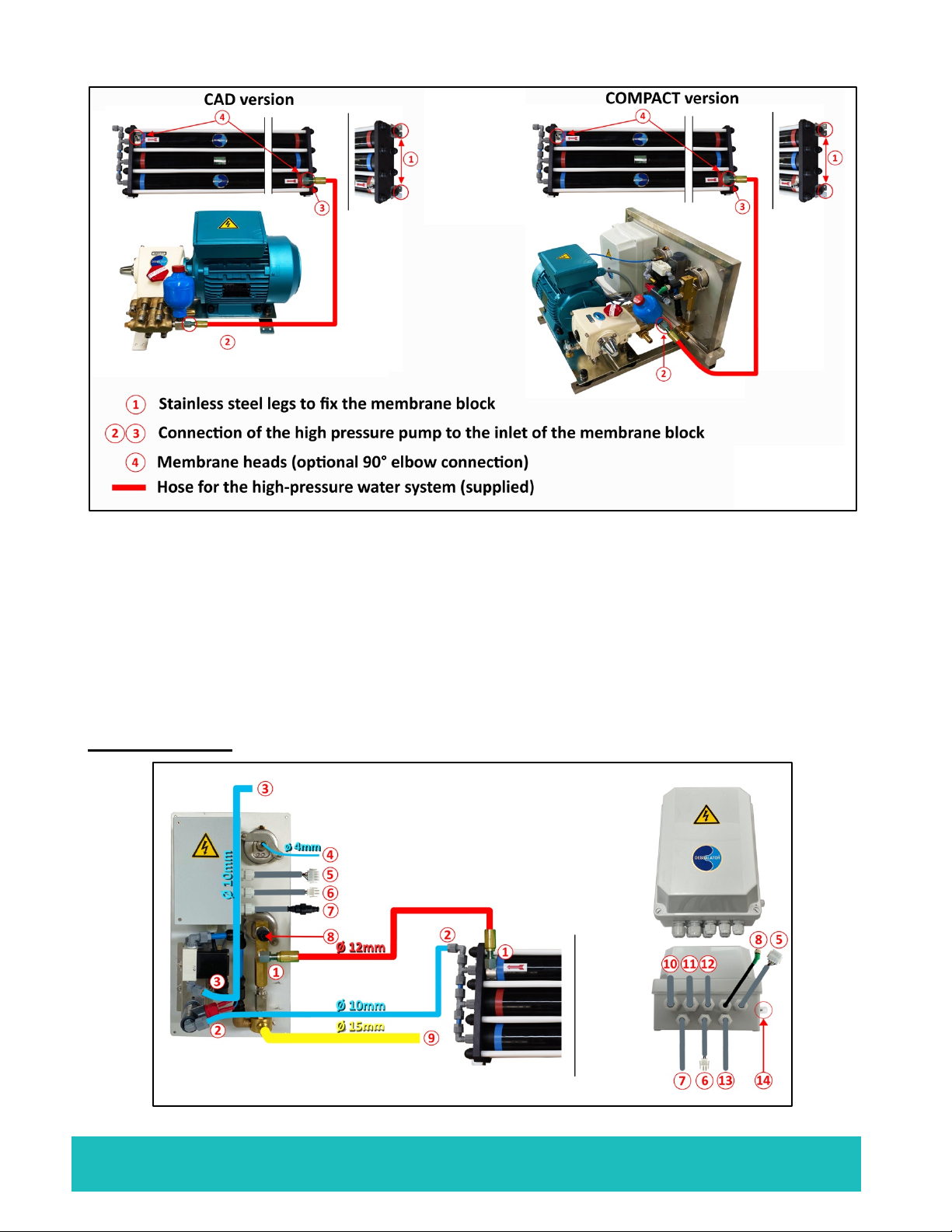
5) Membrane Block
Ø The membrane block should preferably be mounted horizontally (on the base or
side). A vertical position could lead to a yield/output loss over time.
Ø Fastening is done using self-tapping screws in the stainless-steel brackets .
Ø It is necessary to sheath the pipe connecting the output of the high pressure pump
to the inlet of the membranes because of the vibrations, which might lead to
leaks if the pipe is attached or in direct contact with something.
Ø The installation of the high-pressure nozzles must be carried out according to their
assembly instructions (see Appendix A2).
Ø Put some Loctite or threadlock on the 2 male and female cones before tightening.
Ø Available as an option: 90° elbow high-pressure nozzle for the inlet and outlet of
the membranes .
WARNING!
Never work with the power on! Turn off the power of your
entire system.
PRO COMPACT & CAD D90 to D200 v2.4 Page 12
6) Control panel
The control panel must be mounted on a vertical panel.
Ensure unrestricted access to the back of the control panel, this will make connections
easier. You should place it in a place where the light indicators are visible.
Example: below or on the sides of cupboards, under the chart or centre table, on the front
panel of a rear berth etc.
CAD version :
PRO COMPACT & CAD D90 to D200 v2.4 Page 13
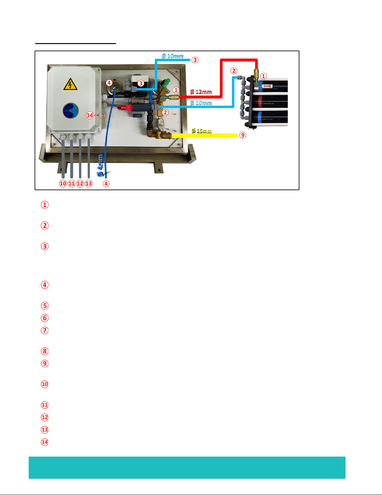
COMPACT version:
Black high-pressure hose to connect the membrane outlet to the pressure sensor of
the control panel.
Blue Serto hose to connect the water production outlet of the membranes to the inlet
of the switchboard probe.
Tricoclair hose with an inside Ø of 10 mm (allow a length of 20 meters), which you
must connect either directly to the tanks, or to the distribution clarinet or to the inlet of
the fresh water unit, provided that there is no valve at the outlet of the fresh water
tank.
4mm capillary tube. It connects to the LP manometer and connects to the side of the
HP pump.
12-pin plug, to be connected from the control panel to the electrical box.
2-pin plug, to be connected from the control panel to the electrical box.
Screw socket with 2-pin domino, connects to the 2-wire cable coming out of the
electrical box.
Screw socket to connect the electrical box to the pressure sensor on the control panel.
Ø 15mm discharge pipe, not supplied, which goes from the control panel to the boat's
discharge thru-hull.
230V (or 400V) power cable of the electrical box, to be connected to the output of the
circuit breaker.
Motor power cable.
Pre-pump power cable.
Power cable for the rinsing solenoid valve located on the pre-filters.
Reset fuse if the pre-pump impeller is blocked.
1.

PRO COMPACT & CAD D90 to D200 v2.4 Page 14
7) Mini Remote Control (optional)
General presentation:
The Dessalator® Mini Remote Control Dessalator allows
you to manage and monitor the watermaker.
You can start and shut down the machine simply by
pressing a single button on the Mini Remote Control. The
3 light indicators on the Mini Remote control have the
same functions as the 3 lights on the watermaker itself.
You can also schedule the automatic shutdown of the
watermaker after a given time of operation.
The Mini Remote is very intuitive, which is why this quick
guide only describes the basic functions and is meant to
serve as a convenient reference.
1: DISPLAY
2: RED LIGHT – ALARM
3: YELLOW LIGHT – POOR QUALITY
4: GREEN LIGHT – GOOD QUALITY
5: DOWN BUTTON
6: ON / OFF BUTTON
7: UP BUTTON
8: ENTER / CONFIRM BUTTON
9: DISPLAY TEXT LINE 1 – STATUS/INFO
10: DISPLAY TEXT LINE 2 – STATUS/INFO
11: PRESSURE INDICATOR
➥
Note: in the event of an alarm, you must restart the machine from the control
panel (and not from the Mini Control)

PRO COMPACT & CAD D90 to D200 v2.4 Page 15
Start-Up
1) Precautions before start-up
Mandatory:
Ø When using the device for the first time, after changing the filter, after the boat has
been grounded or stopped for a long time, you should flush the system using fresh
water by operating the three-way valve on the pre-pump. Position the valve upwards
in the fresh water position (see Appendix A3).
Purge the system for 1 minute: watermaker must be stopped and the pressure
regulator open (counterclockwise).
Ø Once the system is filled, put the valve back in seawater position (see Appendix A3).
➥
Note: If you are not going to use the watermaker at all for a month or more, we
recommend to either sterilize the membranes for storage (for a maximum duration of 6
months) or to rinse it out at least once a month.
Before starting the system back up, we recommend rinsing it out for two minutes (see
Appendix A3).
WARNING!
Before starting-up, check that the valves are open.

PRO COMPACT & CAD D90 to D200 v2.4 Page 16
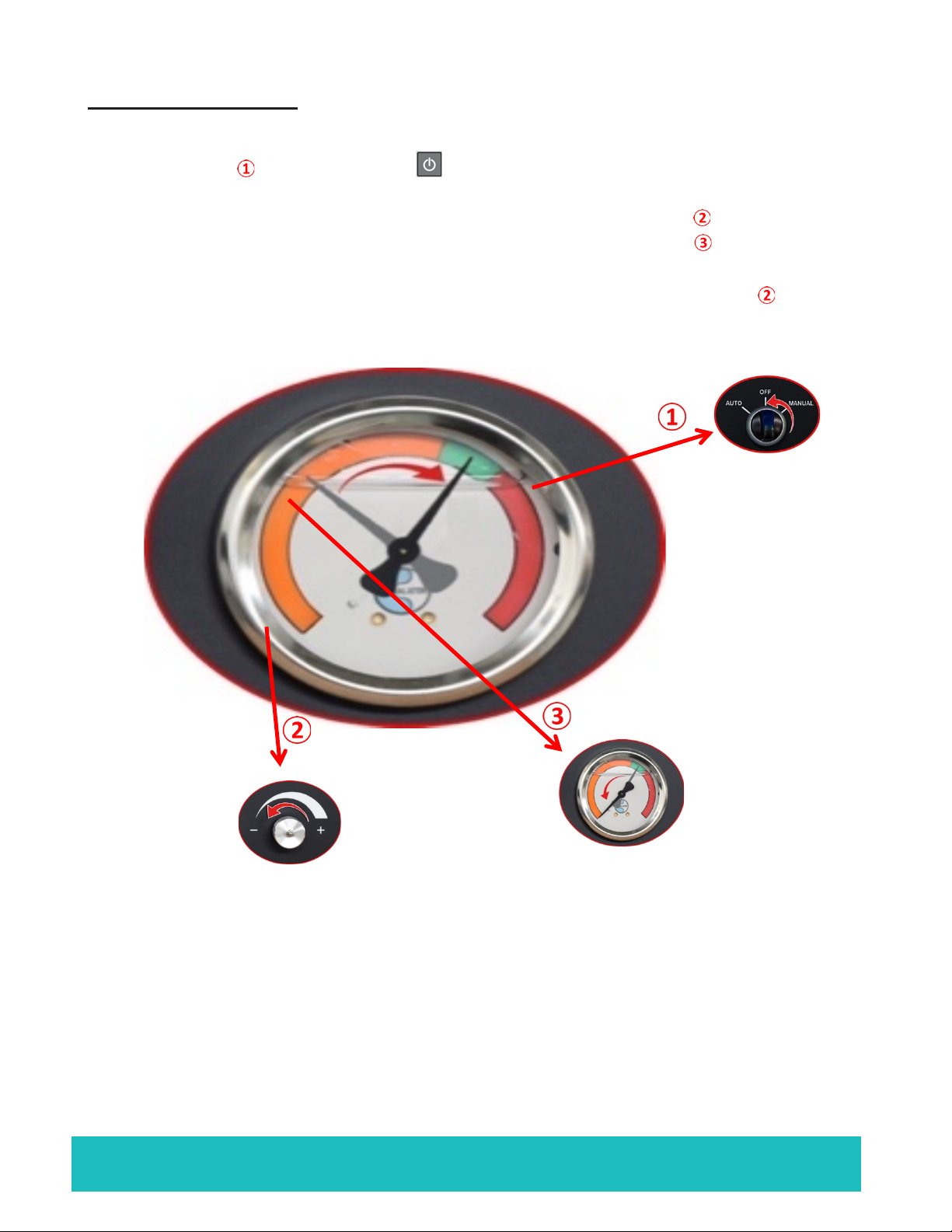
2) Starting-up the watermaker
CAD version:
Follow the procedure below:
Ø Set switch to "Manual" and press START or press on the Mini Remote
Control (which is optional, see procedure in paragraph 5).
Ø The system is rinsed for 5 seconds using fresh water.
Ø The low-pressure pump starts up, the needle on the low pressure gauge rises
to the green area.
Ø Now turn the pressure regulating dial to the right (clockwise), until the needle
of the high-pressure manometer reaches the orange zone. Continue to
gradually adjust until it reaches the beginning of the green zone
This pressure build-up procedure should last approximately 1 minute.
Make sure the pressure appears to be stable. The purpose of the above procedure is to
expel the air from the circuit and to have better pressure stability when the watermaker is
functioning.
PRO COMPACT & CAD D90 to D200 v2.4 Page 17
COMPACT version:
Follow the procedure below:
Ø Set switch to "Manual" and press START or press on the Mini Remote
Control (which is optional, see procedure in paragraph 5).
Ø The low pressure pump starts up, the needle on the low pressure gauge rises
to the green area.
Ø Now turn the pressure regulating dial to the right (clockwise), until the needle
of the high pressure manometer reaches the orange zone. Continue to
gradually adjust until it reaches the beginning of the green zone
This pressure build-up procedure should last approximately 1 minute.
➥Note: Setting the pressure to too high a level will force the watermaker stop and the
red light will come one. If this happens, decrease the pressure with the pressure
regulating dial and restart the start-up process above.
The fresh water yield depends on the temperature of the sea water and the cleanliness
of the 5 & 25 micron filters (in the pre-filter).

PRO COMPACT & CAD D90 to D200 v2.4 Page 18
3) Stopping the watermaker: without rinsing of the membranes
It is not necessary to rinse your membranes if you use your watermaker regularly.
CAD version:
Follow the procedure below:
Ø Set switch to "OFF" or press on the Mini Remote Control press (which is
optional, see procedure in paragraph 5).
Ø Lower the pressure by turning the pressure regulating dial to the left
(counterclockwise) until the needle of the high-pressure gauge reaches its
minimum.
Ø Once the dial cannot be turned further, reopen the pressure regulating dial by a
¼ of a turn (to the right).
PRO COMPACT & CAD D90 to D200 v2.4 Page 19
Version COMPACT :
Follow the procedure below:
Ø Set switch to "OFF" or press on the Mini Remote Control press (which is
optional, see procedure in paragraph 5).
Ø Lower the pressure by turning the pressure regulating dial to the left
(counterclockwise) until the needle of the high-pressure gauge reaches its
minimum.
Ø Once the dial cannot be turned further, reopen the pressure regulating dial by a
¼ of a turn (to the right).
Beyond 10 days without use, it is best to rinse the membranes before the watermaker is
started-up again (see manual rinse procedure in Appendix A3).
The rinsing procedure should be performed every month.
If you’re not going to use the watermaker at all, the membranes must be sterilized for
storage (for a maximum period of 6 months).

PRO COMPACT & CAD D90 to D200 v2.4 Page 20
4) Stopping the watermaker: with automatic rinsing of the membranes
A rinsing must be carried out if the watermaker is not going to be used for more than 3
weeks.
CAD version: Follow the procedure below:
After using the watermaker, do not turn it off.
Ø While the watermaker is still running, turn the pressure regulating dial all the
way to the left (counterclockwise) to lower the pressure of the gauge .
Ø Once the dial cannot be turned further, reopen the pressure regulating dial by a
¼ of a turn (to the right).
Ø The watermaker will stop producing water and will enter the rinsing procedure. The
green and yellow LEDs on the control panel will light up, indicating that the rinsing
procedure has started. This should take 60 seconds and stop automatically. The
green and yellow LEDs will turn off and the only indicator remaining will be the
blinking blue LED on the ON / OFF switch , to remind you to turn off your
watermaker by switching it to "OFF".
Automatic flushing is the best way to flush your system as it not only replaces
seawater with fresh water, but it also washes your pre-filter and allows to discharge
to the sea (through the suction through-hull) all impurities and debris accumulated
in the filter bowl.
This manual suits for next models
3
Table of contents
Other DESSALATOR Industrial Equipment manuals


Popular Industrial Equipment manuals by other brands


ABB
ABB HT580592 Operation manual

Trainsway
Trainsway ZH650 Installation and operating instructions

Sumitomo Drive Technologies
Sumitomo Drive Technologies TAPER-GRIP ST Installation and Maintenance

Wallenstein
Wallenstein P3 PULSE WP1624 Operator's manual

Mark 7
Mark 7 1050 PRO Autodrive user manual

ABB
ABB HT596785 Operation manual