NI PXI-5122 User manual

GETTING STARTED GUIDE
NI PXI/PXIe/PCI-5122
14-Bit, 100 MS/s PXI Oscilloscope
Note Before you begin, install and configure your chassis and controller.
This document explains how to install, configure, and test the PXI/PXIe/PCI-5122.
To access PXI/PXIe/PCI-5122 documentation, including the NI PXI/PXIe/PCI-5122 Getting
Started Guide, go to Start»All Programs»National Instruments»NI-SCOPE»
Documentation.
Caution You can impair the protection provided by the PXI/PXIe/PCI-5122 if you
use it in a manner not described in this document.
Contents
Electromagnetic Compatibility Guidelines...............................................................................2
Verifying the System Requirements......................................................................................... 2
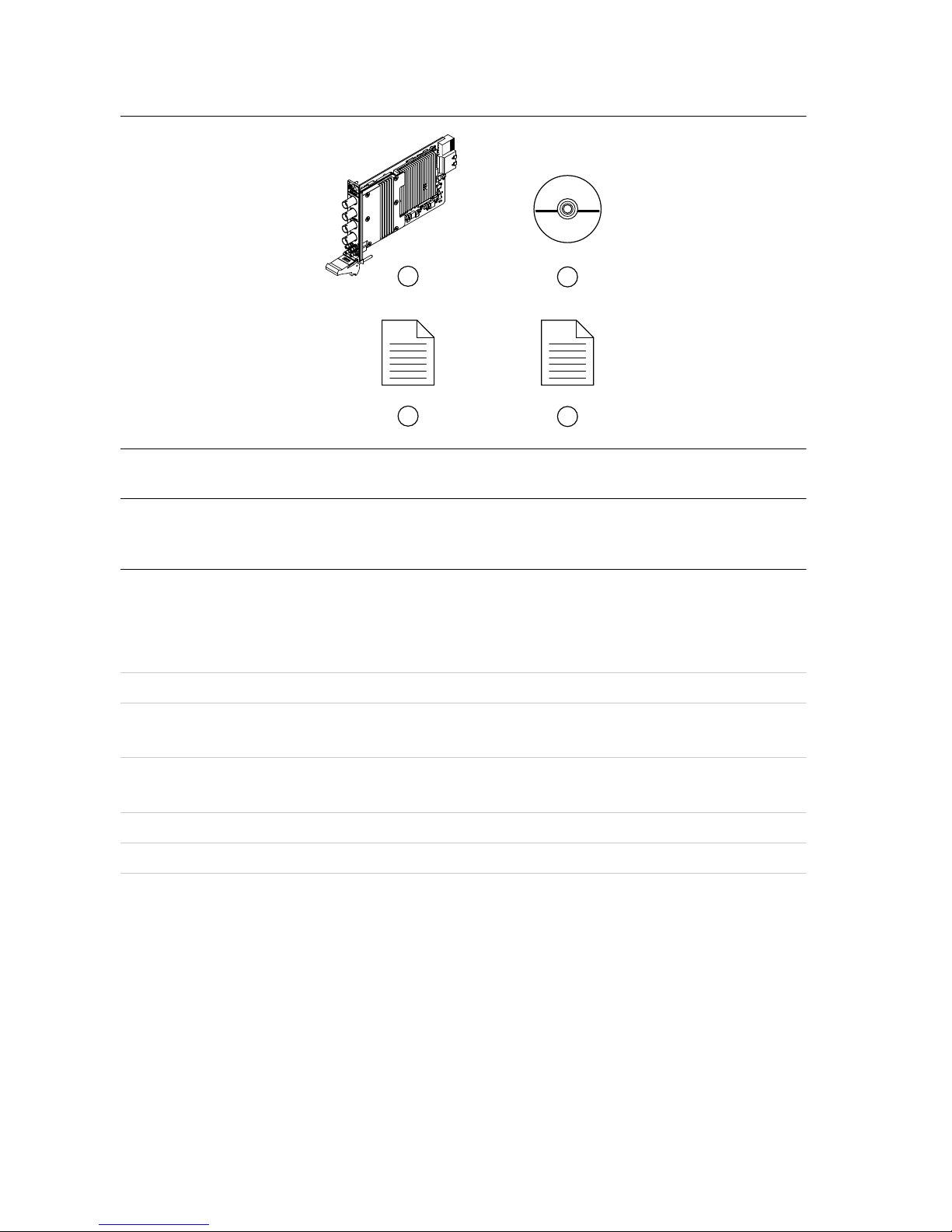
Unpacking the Kit.....................................................................................................................2
Kit Contents...................................................................................................................... 3
Preparing the Environment....................................................................................................... 3
PXI Modules..................................................................................................................... 3
PXI Express Modules....................................................................................................... 4
PCI Modules..................................................................................................................... 4
Installing the Software.............................................................................................................. 4
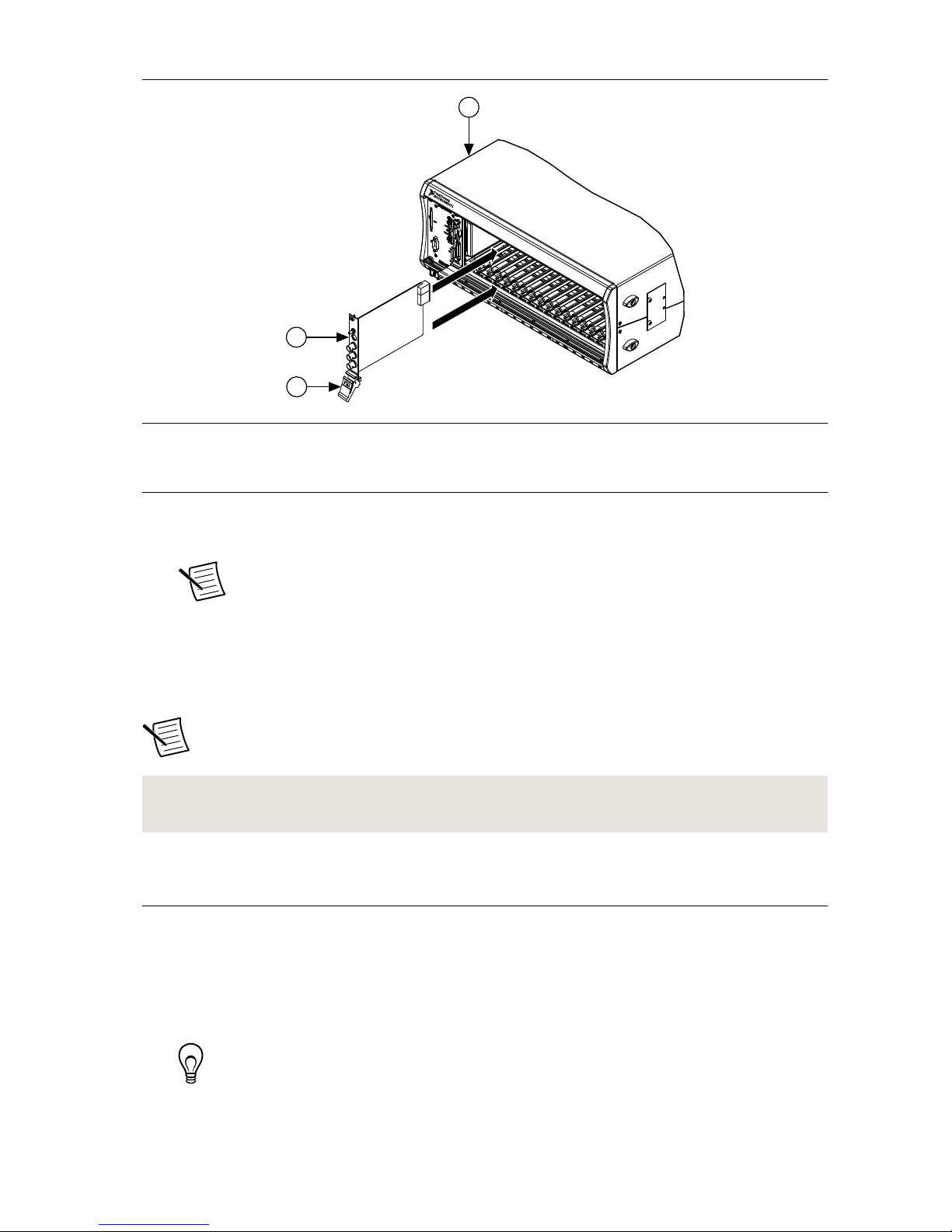
Installing the PXI/PXIe-5122................................................................................................... 5
Installing the PCI-5122.............................................................................................................6
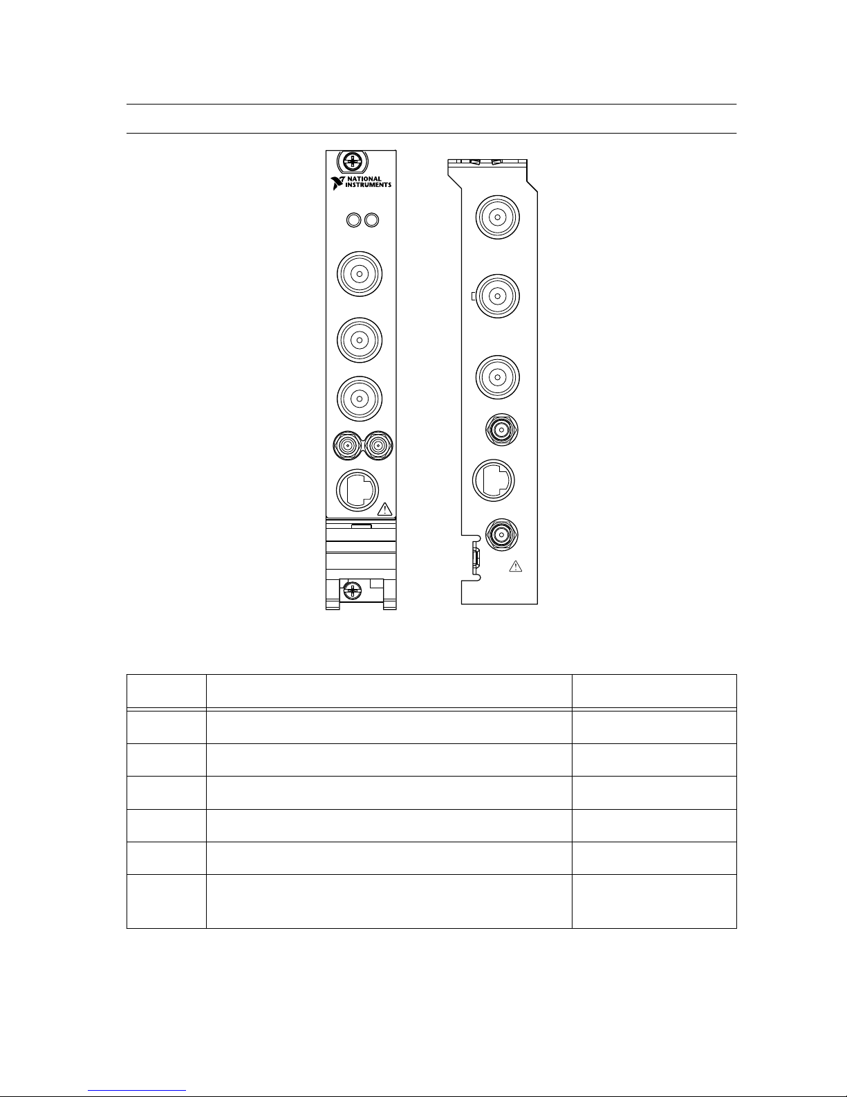
Front Panel Connectors and Indicators.....................................................................................8
Configuring the PXI/PXIe/PCI-5122 in MAX......................................................................... 9
Programming the PXI/PXIe/PCI-5122................................................................................... 10
NI-SCOPE Examples......................................................................................................11
Making a Measurement...........................................................................................................11
Making a Measurement with NI-SCOPE SFP................................................................11
Making a Measurement with LabVIEW.........................................................................11
Setting Up SMC-Based Devices for Synchronization............................................................12
PXI and PXI Express Modules....................................................................................... 12
PCI Modules................................................................................................................... 12
Troubleshooting...................................................................................................................... 12
Why Is the ACCESS LED Off When the Chassis Is On?.............................................. 12
What Should I Do if the PXI/PXIe/PCI-5122 Doesn't Appear in MAX?...................... 13

What Should I Do if the Module Fails the Self-Test?.....................................................13
Thermal Shutdown Error................................................................................................ 14
Where to Go Next................................................................................................................... 15
Worldwide Support and Services............................................................................................15
Electromagnetic Compatibility Guidelines
This product was tested and complies with the regulatory requirements and limits for
electromagnetic compatibility (EMC) stated in the product specifications. These requirements
and limits provide reasonable protection against harmful interference when the product is
operated in the intended operational electromagnetic environment.
This product is intended for use in industrial locations. However, harmful interference may
occur in some installations, when the product is connected to a peripheral device or test object,
or if the product is used in residential or commercial areas. To minimize interference with
radio and television reception and prevent unacceptable performance degradation, install and
use this product in strict accordance with the instructions in the product documentation.
Furthermore, any changes or modifications to the product not expressly approved by National
Instruments could void your authority to operate it under your local regulatory rules.
Verifying the System Requirements
To use the PXI/PXIe/PCI-5122, your system must meet certain requirements. For more
information about minimum system requirements, recommended system, and supported
application development environments (ADEs), refer to the readme, which is available on the
software media or online at ni.com/updates.
Unpacking the Kit
Caution To prevent electrostatic discharge (ESD) from damaging the device,
ground yourself using a grounding strap or by holding a grounded object, such as
your computer chassis.
1. Touch the antistatic package to a metal part of the computer chassis.
2. Remove the device from the package and inspect the device for loose components or any
other sign of damage.
Caution Never touch the exposed pins of connectors.
Note Do not install a device if it appears damaged in any way.
3. Unpack any other items and documentation from the kit.
Store the device in the antistatic package when the device is not in use.
2| ni.com | NI PXI/PXIe/PCI-5122 Getting Started Guide

Kit Contents
3
2
1
4
1. NI PXI/PXIe/PCI-5122
2. Driver Software DVD
3. NI PXI/PXIe/PCI-5122 Getting Started Guide
4. Maintain Forced-Air Cooling Note to Users
Preparing the Environment
Ensure that the environment in which you are using the PXI/PXIe/PCI-5122 meets the
following specifications.
PXI Modules
Operating Environment
Ambient temperature range 0 °C to 55 °C (Tested in accordance with
IEC 60068-2-1 and IEC 60068-2-2.)
Relative humidity range 10% to 90%, noncondensing (Tested in
accordance with IEC 60068-2-56.)
Maximum altitude 2,000 m (at 25 °C ambient temperature)
Pollution Degree 2
Indoor use only.
NI PXI/PXIe/PCI-5122 Getting Started Guide | © National Instruments | 3

PXI Express Modules
Operating Environment
Ambient temperature range 0 °C to 55 °C (Tested in accordance with
IEC 60068-2-1 and IEC 60068-2-2. Meets
MIL-PRF-28800F Class 3 low temperature
limit and MIL-PRF-28800F Class 2 high
temperature limit.)
Relative humidity range 10% to 90%, noncondensing (Tested in
accordance with IEC 60068-2-56.)
Maximum altitude 2,000 m (800 mbar) (at 25 °C ambient
temperature)
Pollution Degree 2
Indoor use only.
PCI Modules
Operating Environment
Ambient temperature range 0 °C to 45 °C (Tested in accordance with
IEC 60068-2-1 and IEC 60068-2-2.)
Relative humidity range 10% to 90%, noncondensing (Tested in
accordance with IEC 60068-2-56.)
Maximum altitude 2,000 m (at 25 °C ambient temperature)
Pollution Degree 2
Indoor use only.
Caution Clean the hardware with a soft, nonmetallic brush. Make sure that the
hardware is completely dry and free from contaminants before returning it to
service.
For complete specifications, refer to specifications document for your device at ni.com/
manuals.
Installing the Software
You must be an Administrator to install NI software on your computer.
1. Install an ADE, such as LabVIEW or LabWindows™/CVI™.
2. Insert the driver software media into your computer. The installer should open
automatically.
4| ni.com | NI PXI/PXIe/PCI-5122 Getting Started Guide

If the installation window does not appear, navigate to the drive, double-click it, and
double-click autorun.exe.
3. Follow the instructions in the installation prompts.
Note Windows users may see access and security messages during
installation. Accept the prompts to complete the installation.
4. When the installer completes, select Restart in the dialog box that prompts you to restart,
shut down, or restart later.
Installing the PXI/PXIe-5122
Caution To prevent damage to the PXI/PXIe/PCI-5122 caused by ESD or
contamination, handle the module using the edges or the metal bracket.
1. Ensure the AC power source is connected to the chassis before installing the module.
The AC power cord grounds the chassis and protects it from electrical damage while you
install the module.
2. Power off the chassis.
3. Inspect the slot pins on the chassis backplane for any bends or damage prior to
installation. Do not install a module if the backplane is damaged.
4. Remove the black plastic covers from all the captive screws on the module front panel.
5. Identify a supported slot in the chassis. The following figure shows the symbols that
indicate the slot types.
Figure 1. Chassis Compatibility Symbols
NI PXIe-1062Q
1
2
3
4
5
1. PXI Express System Controller Slot
2. PXI Peripheral Slot
3. PXI Express Hybrid Peripheral Slot
4. PXI Express System Timing Slot
5. PXI Express Peripheral Slot
PXI modules can be placed in PXI peripheral slots or PXI Express Hybrid peripheral
slots. PXI Express modules can be placed in PXI Express peripheral slots, PXI Express
Hybrid peripheral slots, or PXI Express System Timing slots.
6. Touch any metal part of the chassis to discharge static electricity.
7. Ensure that the ejector handle is in the downward (unlatched) position.
8. Place the module edges into the module guides at the top and bottom of the chassis. Slide
the module into the slot until it is fully inserted.
NI PXI/PXIe/PCI-5122 Getting Started Guide | © National Instruments | 5

Figure 2. Module Installation
2
3
NI PXIe-1075
1
1. Chassis
2. Hardware Module
3. Ejector Handle in Downward (Unlatched) Position
9. Latch the module in place by pulling up on the ejector handle.
10. Secure the module front panel to the chassis using the front-panel mounting screws.
Note Tightening the top and bottom mounting screws increases mechanical
stability and also electrically connects the front panel to the chassis, which can
improve the signal quality and electromagnetic performance.
11. Cover all empty slots using EMC filler panels or fill using slot blockers to maximize
cooling air flow, depending on your application.
12. Power on the chassis.
Note For more information about maximizing cooling air flow, refer to the
Maintain Forced-Air Cooling Note to Users included in your kit.
Related Information
Why Is the ACCESS LED Off When the Chassis Is On? on page 12
Installing the PCI-5122
1. Power off and unplug the computer.
2. Access the computer system expansion slots. This step might require you to remove one
or more access panels on the computer case.
3. Locate a compatible slot and remove the corresponding slot cover on the computer back
panel. PCI-5122 modules can only be inserted into PCI slots.
Tip To maximize airflow and extend the life of the PCI device, leave any
adjacent PCI slots empty.
6| ni.com | NI PXI/PXIe/PCI-5122 Getting Started Guide

4. Touch any metal part of the computer to discharge any static electricity.
5. Insert the module into the slot you selected. Gently rock the module in to place without
forcing it.
Figure 3. Module Installation
1
2
3
1. Module
2. System Expansion Slot
3. PC
6. Secure the module mounting bracket to the computer back panel rail.
Note Tightening the top mounting screw increases mechanical stability and
also electrically connects the front panel to the chassis, which can improve the
signal quality and electromagnetic performance.
7. Some computer manufacturers use a securing lever made of plastic to secure PCI devices;
such a lever is unacceptable and must be removed. Use the screw provided in the kit to
screw down the device. Otherwise, you must use a different computer chassis.
8. Replace any access panels on the computer case.
9. Power on your computer.
10. Verify that spread-spectrum clocking is enabled in the PC BIOS. For information about
how to verify this setting, refer to the PC user documentation
Note For SMC-based devices, spread-spectrum clocking varies the clock
signal to spread the timing clock signal over a small frequency range. Disabling
spread-spectrum clocking may affect the accuracy of device specifications.
NI PXI/PXIe/PCI-5122 Getting Started Guide | © National Instruments | 7

Front Panel Connectors and Indicators
Figure 4. PXI/PXIe/PCI-5122 Front Panels
ACCESS ACTIVE
CH 0
CH 1
CH 1
CH 0
TRIG
TRIG
AUX I/O
AUX I/O
+5 V
MAX
5 V
MAX
CLK IN
CLK IN
CLK OUT
CLK OUT
Table 1. PXI/PXIe/PCI-5122 Front Panel Connectors
Label Function Connector Type
CH 0 Analog input BNC female
CH 1 Analog input BNC female
TRIG External analog trigger BNC female
CLK IN Sample clock input and Reference clock input SMB jack
CLK OUT Sample clock output and Reference clock output SMB jack
AUX I/O PFI 0 and PFI 1 lines for digital trigger input/output
and probe compensation (PFI 1 only).
9-pin mini-circular DIN
8| ni.com | NI PXI/PXIe/PCI-5122 Getting Started Guide

Table 2. PXI/PXIe/PCI-5122 Front Panel Indicators
Label Function
ACCESS Indicates the status of the PCI bus and the interface from the PXI/PXIe-5122 to
the controller.
ACTIVE Indicates the status of the onboard acquisition hardware of the PXI/PXIe-5122
Figure 5. PXI/PXIe/PCI-5122 9-Pin DIN Connector Pin Assignments
4
3
5
6
7
8
9
1
2
1. +5 V (Fused)
2. GND
3. Reserved
4. Reserved
5. Reserved
6. PFI 1
7. Reserved
8. Reserved
9. PFI 0
Configuring the PXI/PXIe/PCI-5122 in MAX
Use Measurement & Automation Explorer (MAX) to configure your NI hardware. MAX
informs other programs about which devices reside in the system and how they are configured.
MAX is automatically installed with NI-SCOPE.
1. Launch MAX.
2. In the configuration tree, expand Devices and Interfaces to see the list of installed
devices.
Installed devices appear under the name of their associated chassis.
3. Expand your Chassis tree item.
MAX lists all devices installed in the chassis. Your default device names may vary.
Note If you do not see your device listed, press <F5> to refresh the list of
installed devices. If the device is still not listed, power off the system, ensure
the device is correctly installed, and restart.
4. Record the device identifier MAX assigns to the hardware. Use this identifier when
programming the PXI/PXIe/PCI-5122.
5. Self-test the device by selecting the device in the configuration tree and clicking Self-
Test in the MAX toolbar.
NI PXI/PXIe/PCI-5122 Getting Started Guide | © National Instruments | 9

The MAX self-test performs a basic verification of hardware resources.
Related Information
Making a Measurement on page 11
What Should I Do if the PXI/PXIe/PCI-5122 Doesn't Appear in MAX? on page 13
What Should I Do if the Module Fails the Self-Test? on page 13
Programming the PXI/PXIe/PCI-5122
You can acquire data interactively using the NI-SCOPE SFP, or you can use the NI-SCOPE
instrument driver to program your device in the supported ADE of your choice.
Table 3. PXI/PXIe/PCI-5122 Programming Options
Application
Programming
Interface (API)
Location Description
NI-SCOPE SFP Available from the start
menu at Start»All
Programs»National
Instruments»NI-SCOPE»
NI-SCOPE Soft Front
Panel.
The NI-SCOPE SFP acquires, controls,
analyzes, and presents data, similar to
stand-alone oscilloscopes. The
NI-SCOPE SFP operates on the PC, so
you can view and control waveforms
directly from your computer. You can
also run multiple sessions of the
NI-SCOPE SFP simultaneously.
NI-SCOPE
Instrument Driver
LabVIEW—Available on
the LabVIEW Functions
palette at Measurement
I/O»NI-SCOPE.
The NI-SCOPE API configures and
operates the device hardware and
provides customizable acquisition,
control, analysis, and measurement
options using LabVIEW VIs or
LabWindows/CVI functions.
C or LabWindows/CVI—
Available at Program
Files»IVI Foundation»
IVI»Drivers»niScope.
Microsoft Visual C/C++—
Use examples located in the
file directory Users
\Public\Documents
\National
Instruments\NI–SCOPE
\examples.
You can modify an NI-SCOPE C
example to create an application with
Microsoft Visual C/C++. Copy an
NI-SCOPE example to copy required
project settings for include paths and
library files. Alternatively, refer to the
Creating an Application with Microsoft
Visual C and C++ topic of the NI High-
Speed Digitizers Help to manually add all
required include and library files to your
project.
10 | ni.com | NI PXI/PXIe/PCI-5122 Getting Started Guide

NI-SCOPE Examples
Examples demonstrate the functionality of the device and serve as programming models and
building blocks for your own applications.
The NI Example Finder is a utility available for some ADEs that organizes examples into
categories and allows you to easily browse and search installed examples. You can see
descriptions and compatible hardware models for each example, or see all the examples
compatible with one particular hardware model.
To locate examples, refer to the following table:
Table 4. Locating NI-SCOPE Examples
Application Development
Environment (ADE)
Locating Examples
LabVIEW or
LabWindows/CVI
Locate examples with the NI Example Finder. Within
LabVIEW or LabWindows/CVI, select Help»Find
Examples, and navigate to Hardware Input and Output»
Modular Instruments.
ANSI C or Visual Basic Locate examples in the file directory Users\Public
\Public Documents\National Instruments\NI–
SCOPE\examples.
Making a Measurement
You can make a measurement interactively using the NI-SCOPE SFP or programmatically
using LabVIEW.
Making a Measurement with NI-SCOPE SFP
1. Connect CH 0 to an input signal.
2. Launch the NI-SCOPE SFP from the Start menu.
3. In the Select Device dialog box, select the device name assigned to the device in MAX.
4. Click Auto to adjust the acquisition display.
5. If the SFP is not already running, click Run.
Making a Measurement with LabVIEW
1. Launch LabVIEW.
2. Select Help»Find Examples.
3. Open the example VI that you want to use by selecting Hardware Input and Output»
Modular Instruments»NI-SCOPE (High-Speed Digitizers).
Tip If you are not sure which example to run, use the Quick Start VI, which is
found under Hardware Input and Output»Modular Instruments»NI-
SCOPE (High-Speed Digitizers)»Demos»niScope EX Quick Start.vi.
NI PXI/PXIe/PCI-5122 Getting Started Guide | © National Instruments | 11

4. Follow any setup instructions in the VI.
5. In the Resource Name drop-down menu, select the device name assigned to the device in
MAX.
6. Click Run to run the example program.
Setting Up SMC-Based Devices for
Synchronization
PXI and PXI Express Modules
You must identify the PXI/PXI Express system controller by completing the following steps:
1. Launch MAX.
2. In the MAX configuration pane, expand the chassis tree.
3. Right-click the name of the chassis you are using, and select Identify As.
4. Select your controller from the list. For example, select External PC if you are using an
MXI controller in an external PC.
PCI Modules
You must configure the RTSI cable by completing the following steps:
1. Connect an RTSI cable between the PCI devices to physically share triggers and/or
clocks.
2. Launch MAX.
3. In the MAX configuration pane, right-click Devices and Interfaces, and select Create
New.
4. In the dialog box that opens, select NI-RTSI Cable.
5. Click Finish.
6. In the MAX configuration pane, right-click the NI-RTSI cable, select Add Device to NI-
RTSI Cable, and select the device you want to add.
For more information about connecting PCI devices, refer to NI High-Speed Digitizers
Help»Programming»Reference»NI-TClk Synchronization Help.
Troubleshooting
Why Is the ACCESS LED Off When the Chassis Is
On?
The LEDs may not light until the module has been configured in MAX. Before proceeding,
verify that the PXI/PXIe/PCI-5122 appears in MAX.
If the ACCESS LED fails to light after you power on the chassis, a problem may exist with the
chassis power rails, a hardware module, or the LED.
12 | ni.com | NI PXI/PXIe/PCI-5122 Getting Started Guide

Caution Apply external signals only while the PXI/PXIe/PCI-5122 is powered on.
Applying external signals while the module is powered off may cause damage.
1. Disconnect any signals from the module front panels.
2. Power off the chassis.
3. Remove the module from the chassis and inspect it for damage. Do not reinstall a
damaged module.
4. Install the module in a different chassis slot from which you removed it.
5. Power on the chassis.
Note If you are using a MXI controller, power on the chassis before powering
on the computer.
6. Verify that the module appears in MAX.
7. Reset the module in MAX and perform a self-test.
If the ACCESS LED still fails to light and failures continue, contact NI technical support or
visit ni.com/support.
Related Information
Installing the PXI/PXIe-5122 on page 5
Installing the PCI-5122 on page 6
What Should I Do if the PXI/PXIe/PCI-5122 Doesn't
Appear in MAX?
1. In the MAX configuration tree, expand Devices and Interfaces.
2. Expand the Chassis tree to see the list of installed hardware, and press <F5> to refresh
the list.
3. If the module is still not listed, power off the system, ensure that all hardware is correctly
installed, and restart the system.
4. Navigate to the Device Manager.
Operating System Description
Windows 10/8.1 Right-click the Start button, and select Device Manager.
Windows 7 Select Start»Control Panel»Device Manager.
5. If you are using a PXI or PXI Express controller, verify that a National Instruments
entry appears in the System Devices list. Reinstall NI-SCOPE and the module if error
conditions appear in the list. If you are using an MXI controller, right-click PCI-to-PCI
Bridge, and select Properties from the shortcut menu to verify that the bridge is enabled.
What Should I Do if the Module Fails the Self-Test?
1. Restart the system.
2. Launch MAX, and perform the self-test again.
NI PXI/PXIe/PCI-5122 Getting Started Guide | © National Instruments | 13

3. Power off the chassis.
4. Reinstall the failed module in a different slot.
5. Power on the chassis.
6. Perform the self-test again.
Thermal Shutdown Error
If you receive an over-temperature or thermal shutdown error and your device shuts down,
complete the following steps to re-enable your device:
1. Power off the computer or chassis that contains the device.
2. Reinstall the device and make any necessary adjustments to make sure that the device is
effectively cooled.
3. Power on the computer or chassis.
Note The thermal shutdown error is reported until the device has cooled to an
acceptable operating temperature and has been successfully reset.
For more information about cooling the device, refer to the Maintain Forced-Air Cooling
Note to Users included in your kit.
Related Information
Installing the PXI/PXIe-5122 on page 5
Installing the PCI-5122 on page 6
14 | ni.com | NI PXI/PXIe/PCI-5122 Getting Started Guide

Where to Go Next
DISCOVER
Services
ni.com/services
NI Community
ni.com/community
Support
ni.com/support
NI Oscilloscopes
ni.com/oscilloscope
CREATELEARN
Getting Started with
LabVIEW
Getting Started with
LabWindows/CVI
EXPLORE
NI PXI/PXIe/PCI-5122
Specifications
NI High-Speed
Digitizers Help
NI-SCOPE Examples
NI High-Speed
Digitizers Help
NI-SCOPE Soft Front Panel
NI-SCOPE Instrument Driver
custom applications within
an application programming
interface (API).
about hardware features
or review device
specifications.
the application development
environment (ADE)
for your application.
more about your products through ni.com.
Located online at ni.com/manuals Located using the NI Example Finder
500MHz Oscilloscope
NI PXIe-5160
Worldwide Support and Services
The NI website is your complete resource for technical support. At ni.com/support, you have
access to everything from troubleshooting and application development self-help resources to
email and phone assistance from NI Application Engineers.
Visit ni.com/services for NI Factory Installation Services, repairs, extended warranty, and
other services.
Visit ni.com/register to register your NI product. Product registration facilitates technical
support and ensures that you receive important information updates from NI.
A Declaration of Conformity (DoC) is our claim of compliance with the Council of the
European Communities using the manufacturer’s declaration of conformity. This system
affords the user protection for electromagnetic compatibility (EMC) and product safety. You
NI PXI/PXIe/PCI-5122 Getting Started Guide | © National Instruments | 15

can obtain the DoC for your product by visiting ni.com/certification. If your product supports
calibration, you can obtain the calibration certificate for your product at ni.com/calibration.
NI corporate headquarters is located at 11500 North Mopac Expressway, Austin, Texas,
78759-3504. NI also has offices located around the world. For telephone support in the United
States, create your service request at ni.com/support or dial 1 866 ASK MYNI (275 6964). For
telephone support outside the United States, visit the Worldwide Offices section of ni.com/
niglobal to access the branch office websites, which provide up-to-date contact information,
support phone numbers, email addresses, and current events.
Refer to the NI Trademarks and Logo Guidelines at ni.com/trademarks for information on NI trademarks. Other
product and company names mentioned herein are trademarks or trade names of their respective companies. For
patents covering NI products/technology, refer to the appropriate location: Help»Patents in your software, the
patents.txt file on your media, or the National Instruments Patent Notice at ni.com/patents. You can find
information about end-user license agreements (EULAs) and third-party legal notices in the readme file for your NI
product. Refer to the Export Compliance Information at ni.com/legal/export-compliance for the NI global trade
compliance policy and how to obtain relevant HTS codes, ECCNs, and other import/export data. NI MAKES NO
EXPRESS OR IMPLIED WARRANTIES AS TO THE ACCURACY OF THE INFORMATION CONTAINED HEREIN AND
SHALL NOT BE LIABLE FOR ANY ERRORS. U.S. Government Customers: The data contained in this manual was
developed at private expense and is subject to the applicable limited rights and restricted data rights as set forth in FAR
52.227-14, DFAR 252.227-7014, and DFAR 252.227-7015.
© 2006—2016 National Instruments. All rights reserved.
376329A-01 Aug16
This manual suits for next models
2
Table of contents
Other NI Test Equipment manuals
Popular Test Equipment manuals by other brands

Datasensing
Datasensing ST 400AD quick start guide

Akron Brass
Akron Brass AFTK-LK-KIT operating instructions

Teledyne
Teledyne T3CP100-2 manual

TRI Electronics
TRI Electronics Gold Tester GT-4000 User instruction

Tektronix
Tektronix 178 Service instructions manual

Johnson Controls
Johnson Controls YORK ROOFTOP ACTIVA 017 / 022 manual