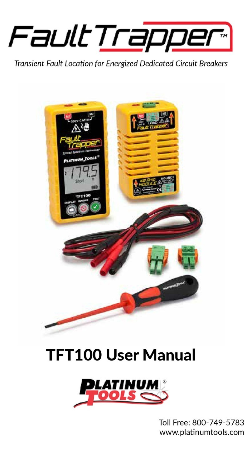
Platinum Tools Fault Trapper TFT100 User manual

Transient Fault Location for Branch Circuit Breakers
TFT100
2450 Turquoise Circle
Newbury Park, CA 91320
Toll Free: 800-749-5783

Fault Trapper™
Transient Fault Location for Branch Circuit Breakers
Toll Free: 800-749-5783 Page 2of 8V 1.3 (draft)
User Manual
Introduction
Fault Trapper™ is a new class of tester intended to locate the distance to a circuit anomaly that is either
intermittently causing a change in the circuit’s characteristics or blowing the circuit breaker. Fault
Trapper™ can capture and save both types of events and saves them separately. If the circuit breaker
trips, the backup battery powers the Fault Trapper™ to allow for an orderly shutdown. The last faults
can be viewed using the battery power. The In-Line Adapter isolates the circuit being monitored from
the breaker panel and all other breakers.
This product should only be used by and connected/disconnected from circuit to be tested by qualified
service personnel or certified electricians.
Features
In line monitoring of branch circuits up to 300 VAC and 40 amps
Fault Location reported as distance from Fault Trapper™.
Simple user interface - Backlit LCD display and three buttons
Back-up battery allows capture of breaker trips/Unpowered display of results
Safety Information
Safety Alert Symbols
To ensure safe operations of the Fault Trapper™, follow instructions carefully when using the unit and
observe warning and caution messages listed in this manual. Failure to observe warnings can result in
severe injury or death and can damage the unit.
•Fault Trapper™ is for use only by persons qualified to work in and around breaker panels.
•Do not use the Fault Trapper™ or cables if they appear damaged or the unit is not working
properly.
•Do not use with voltages and currents higher than the Fault Trapper™ is rated for - 100 to 240Vac
Symbol
Definition
(Exclamation point)
Warning: Potential for
personal injury.
Caution: Potential for
damage to or destruction of
equipment.
(CE symbol)
Conformité Européenne.
Conforms to European
Economic Area directives.
(TRASH SYMBOL)
Disposal information

Fault Trapper™
Transient Fault Location for Branch Circuit Breakers
Toll Free: 800-749-5783 Page 3of 8V 1.3 (draft)
and 40amp branch circuits or less.
•Turn off circuit breaker prior to attaching Fault Trapper™ and inline adapter to circuit to be
monitored.
•Do not use around explosive or flammable gas.
Safety Information (cont.)
•Use only test leads provided between Fault Trapper™ and In-Line adapter.
•Before opening the battery door, remove cables from Fault Trapper™.
•Always wear personal protective equipment when working with the Fault Trapper™
•Do not open case of either the Fault Trapper of the In-Line Adapter with any cables connected to
it
Included Equipment:
Fault Trapper Main Unit
40amp In-Line Adapter
Banana Plug Leader Cable
Two Plug-in 2 Wire Terminal Blocks - 8 to 24 AWG (0.2 to 10mm2)
Optional Accessories:
Spare Plug-in 2 Wire Terminal Blocks
Adapters to Standard Plugs/Outlets for inline monitoring

Fault Trapper™
Transient Fault Location for Branch Circuit Breakers
Toll Free: 800-749-5783 Page 4of 8V 1.3 (draft)
Fault Trapper™ Front Panel and Connections:
Connectors:
1. Power Source - Usually attached to circuit breaker terminal or terminals using plug in terminal
blocks supplied. Screws on terminal block should be tightened to 7in-lbs.
Connectors (continued):
2. Load - Wire or wires removed from circuit breaker attach here
3. Supplied Leader cable connects 40amp adapter to Fault Trapper™.
1
2
4
5
8
6
7
3

Fault Trapper™
Transient Fault Location for Branch Circuit Breakers
Toll Free: 800-749-5783 Page 5of 8V 1.3 (draft)
Display (4.) - Backlit LCD display shows distance to fault, time to fault, fault type and battery status.
Buttons:
5. Display - Used to power unit on briefly to view faults when not powered by AC and to toggle
between a breaker trip fault and a non-breaker trip fault, if there is one.
6. Ignore - Press to ignore events that are part of the circuit’s normal operation.
7. Test - Press button to start a monitoring. Stops a test if running.
8. Distance Units – Hold the Display and Ignore buttons for 3 seconds. The “ft” or “m” icons will flash
denoting the new unit used for measurement.
Caution - Turn off power to circuit the In-Line Adapter is being connected to!
Connecting In Line Adapter to Circuit Breakers (USA)
120V Breaker Connection 240V Breaker Connection
To connect to a 120Vac Standard Breaker (up to 40amps): All connections to the Fault Trapper 40 Amp
adapter are madding using plug in terminal blocks, torque screws to 7in-lbs:
1) Remove the hot wire from the breaker and attach to the load-side of the Fault Trapper 40Amp Adapter,
terminal L1.
2) Connect a white jumper wire from the other load-side terminal, L2, to the neutral/ground bus bar.
3) Connect a jumper wire from the source terminal S2 to the breaker terminal that the wire in step 1 was

Fault Trapper™
Transient Fault Location for Branch Circuit Breakers
Toll Free: 800-749-5783 Page 6of 8V 1.3 (draft)
removed from in step 1.
To connect to 220Vac Standard Breaker (up to 40amps): All connections to the Fault Trapper 40 Amp
adapter are madding using plug in terminal blocks, torque screws to 7in-lbs:
1) Remove the two hot wires from the breakers and attach to the load side of the Fault Trapper 40Amp
Adapter - terminal L1 black wire, terminal L2 red wire.
2) Connect a jumper wire from the source terminal S1 to the breaker terminal that the black wire was
removed from in step 1.
3) Connect a jumper wire from the source terminal S2 to the breaker terminal that the red wire
was removed from in step 1.
120V AFCI or GFCI Breaker Connection
To connect to a 120Vac GFI or AFCI breaker (up to 40amps): All connections to the Fault Trapper 40
Amp adapter are madding using plug in terminal blocks, torque screws to 7in-lbs:
1) Remove the hot and neutral (not the neutral connected to the neutral bus bar) wires from the
breaker and attach to the load side of the Fault Trapper 40Amp Adapter - Terminal L1 black wire,
terminal L2 white wire.
2) Connect a white jumper wire from the other source terminal, S2, to the neutral contact on the
breaker.
3) Connect a black jumper wire from the source terminal S2 to the breaker hot terminal.
Instructions for Use -After Connecting in one of the configurations above and switching on the
breaker(s).
Powering on Unit – Once the unit is powered by the AC power connection the battery level will be
shown on the display. The unit will be ready at this point to run a test. If there is no AC power

Fault Trapper™
Transient Fault Location for Branch Circuit Breakers
Toll Free: 800-749-5783 Page 7of 8V 1.3 (draft)
connection the Display button can be used to power the unit on using battery power to show the results
from a previous test.
Starting a Test – While powered by the AC power connection press the Test button. The Fault Trapper
will not run a test under battery power. The velocity of propagation used for distance measurement is
70% the speed of light, a nominal value for power wiring, and is not configurable.
Test Running – When a test is started boxes running left to right in the test results area and the up
down arrows on the left side will be flashing until a fault is shown. Once a fault is found the up down
arrows will continue to flash while the test is running while the distance to the last fault found is
shown. The lower left portion of the screen denotes the time. Before a fault is found the time will
show how long it has been since the test started. Once a fault is found the last fault will be shown and
the time will show how long the time was between the beginning of the test and the last fault found.
Stopping a Test – The three ways a test can stop are when the A/C power goes down, the Test button
is pressed and when the Ignore button is pressed. When the A/C power goes down the unit will run on
battery power for long enough to finish scanning for the fault which may have caused the A/C to
power off (breaker trip). If a fault occurred with the last 30 seconds before the A/C went down it will
be classified as the “Breaker Trip Fault”, the "Voltage!" icon will be displayed when this occurs. A non-
breaker trip fault (if found earlier during the test) will also be saved. When the Test button is pressed
during a test any fault found will be saved as a “Non-Breaker Trip Fault” and testing halted. A second
press of the Test button will restart testing and clear any previous faults and Ignores.
Ignore Feature - The Ignore button is used to tell the Fault Trapper that a fault it is detecting is part of
the normal operation of the circuit such as a motor starting up or a switch being toggled. Pressing the
Ignore button will save the location information and fault type and resume monitoring. The ignored
fault will be shown on the screen. To clear any saved ignores hold down the ignore button for 3
seconds. “Clr” will be shown on the screen to indicate the ignore fault was cleared. If the Ignore button
is pressed while testing the test will be stopped. If ignore is pressed and there is no fault saved from a
previous test dashes will be shown in the test result area to denote that no event is currently ignored. If
the ignored fault occurs during the last 30 seconds before the A/C power goes down it will still be shown
as the “Breaker Trip Fault”. The ignored fault is +/- 3% of the distance to the ignored fault location
(regardless of being a Short or an Open event).
Test Results - The Display button is used to show test results. If the AC power connection is off the unit
will use the 9 volt battery to power on the display and show the results from the last test. There can be a
“Breaker Trip” fault and a “Non-Breaker Trip” fault. The voltage icon will flash indicating that the fault
shown caused the breaker to trip. Tap the Display button to cycle between the two faults (if there are
more than one). Ft and M units can be toggled by holding down the Display and Ignore buttons for 3
seconds.
Battery Remaining – In the lower right portion of the screen is a battery icon with bars showing how
much remains for the 9V battery. Three bars shows a full battery, two bars is between 33% and 66%,
one bar is between 33% and 10%. A flashing battery outline icon shows that there is less than 10%
battery life remaining. Since the test runs for a short time after the A/C power shuts off it is
recommended to replace the 9V battery (with no A/C power present) once the battery indicator shows
one bar or a flashing battery outline icon.
Fault Trapper™
Transient Fault Location for Branch Circuit Breakers
Toll Free: 800-749-5783 Page 8of 8V 1.3 (draft)
Warning! - Remove any cables attached to the Fault Trapper™ before opening battery compartment!
Changing Battery
1) Remove screw on rear of unit near the middle with a #1 Philips head screwdriver.
2) Remove battery and disconnect from battery snaps.
3) Attach a new 9 volt alkaline battery to the battery snaps and return to battery compartment.
4) Place battery cover in slot and rotate shut. Fasten shut with screw removed. Do not over tighten!
Specifications
Physical Dimensions
Fault Trapper Main Unit
Size: 15.25 x 7.6 x 3.8 cm (6.0 x 3.0 x 1.5 inches)
Weight: 255 grams (9 oz.) With battery
40amp In-Line Adapter
Size: 11.5 x 7.6 x 5.85 cm (4.5 x 3.0 x 2.3 inches)
Weight: 312 grams (11 oz.)
Input Rating:
Fault Trapper Main Unit: 90 to 265 Volts ac rms 50/60 Hz, 4 watts max.
40amp In-Line Adapter: 300 Volts ac rms, 40 amp circuits maximum, supplies power to main unit
Measurement Method: Spread Spectrum Time Domain Reflectometry (SSTDR)
Accuracy: +/-10%
Maximum Length: 300 ft on NM-B or Wire in Conduit
Battery is used to review results when not AC powered
Battery Low Level: Approximately 5.5 volts
Battery Life (9 Volt alkaline battery, typical) - Standby: 2 years
Active: 4 hours typical
Environmental
Temperature -Operating: 0° to 50°C (32° to 122°F)
Storage temperature: -20° to 60°C (-4° to 140°F)
Long Term Storage w/ battery: 35°C maximum (95°F)
Humidity: 10% to 90%, non-condensing
Altitude: 2,000 meters (6,561ft) maximum
Other manuals for Fault Trapper TFT100
1
Table of contents
Other Platinum Tools Test Equipment manuals

Platinum Tools
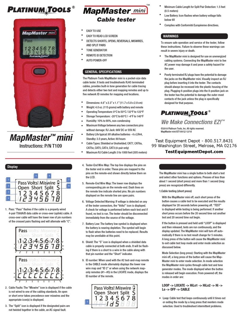
Platinum Tools Net Prowler TNP800 User manual

Platinum Tools
Platinum Tools Net Chaser TNC950AR User manual

Platinum Tools
Platinum Tools Cable Prowler TCB400 User manual

Platinum Tools
Platinum Tools TP220 User manual

Platinum Tools
Platinum Tools VDV MapMaster 2.0 User manual

Platinum Tools
Platinum Tools MapMaster mini User manual

Platinum Tools
Platinum Tools NETXPERT XG2 User manual

Platinum Tools
Platinum Tools Net Prowler TNP700 User manual

Platinum Tools
Platinum Tools VDV MapMaster User manual

Platinum Tools
Platinum Tools NETXPERT XG2 User manual