Detectortesters testifire XTR2 User manual

1
Testire XTR2
USER
MANUAL
detectortesters.com
EU: shift-consult Hubert Scherzinger
Hessenweier 9,79108 Freiburg, DE
Tel: +49 (0) 7665 91 21 74
No Climb Products Ltd.
163 Dixons Hill Road, Welham
Green. Hertfordshire, AL9 7JE,
United Kingdom
Tel +44 (0)1707 282 760

2
Testire XTR2
This product is intended to be used at height.
Exercise great care and always wear appropriate PPE
(personal protective equipment) when operating above
head height in order to avoid the risk of injury.
DO NOT OVER REACH. Keep proper footing and
balance at all times. Proper footing and balance
enables better control of the equipment in
unexpected situations.
Pay particular attention to avoid contact with overhead
items such as light ttings, overhead power cables and
any other objects that could be accidentally dislodged
which might cause danger to the operator or anyone
else in the vicinity.
Avoid prolonged, direct exposure to the vapour
generated by Testire XTR2. Safety Data Sheets for
the Testire XTR2 battery pack and Testire XTR2
Smoke Cartridge are available. It is recommended to
review the safety data sheets for Testire XTR2
Battery Pack and Testire XTR2 Smoke Cartridge
before use (see detectortesters.com).
This product contains hot parts.
DO NOT TOUCH the heat element. It may be very hot
immediately after use and may burn if touched.
Contains precision parts which may be easily damaged
and cause injury. DO NOT TOUCH the smoke uid
intake pipe in the smoke cartridge area or the heat
element in the tester cup.
Contains Lithium Ion rechargeable batteries:
• Do not dismantle, open, shred or incinerate
batteries.
• Do not expose batteries to heat or re. Avoid
storage in direct sunlight.
• Do not short-circuit a battery. Do not store bat-
teries loose in a box or drawer where they may
short-circuit each other or be short-circuited by
other metal objects.
• Do not subject batteries to mechanical shock.
• Keep batteries clean and dry.
• Do not use any charger other than that speci-
cally provided for use with the equipment. Refer
to the manufacturer’s instructions or equipment
manual for proper charging instructions.
• Do not leave a battery on prolonged charge when
not in use.
• Do not use any battery which is not designed for
use with this equipment.
• Do not use the battery in any other application.
• Keep batteries out of the reach of children.
• Dispose of properly.
CAUTIONS & WARNINGS
Warning Caution

3
Testire XTR2
• Read this User Manual completely before using your
Testire XTR2
• Keep this User Manual - save all safety and operational
instructions for future reference.
• Take note of the Warnings - Read carefully and follow all
warning labels on the product and those described in this
User Manual.
• Testire XTR2 is electronic test equipment and care
should be taken when handling and storing. Dropping the
unit on to a hard surface could damage it. Please look after
it, treat it with care for lasting use.
• This product is designed for indoor use only and should
not be subject to harsh environments. It is not designed
for use in hazardous areas (those containing explosive
vapour or dust). Do not use the equipment in places where
temperatures and/or humidity are high or go through
rapid changes including:
◦Direct sunlight
◦Near heat sources (stoves, radiators, etc.)
◦Sandy or dusty environments
◦In the presence of strong magnetic elds
◦Places prone to strong vibration
◦Restrictions detailed in the Technical Information (see
Section 12).
• Testire XTR2 may be used in ceiling and oor voids but
care must be taken to ensure that the unit and cup can
pass through gaps in both directions.
• Stop using Testire XTR2 immediately if you notice any
damage or unusual odours, liquids or sounds coming from
the unit. Turn the power off immediately and consult tech-
nical support and troubleshooting (see section 11).
• Use only approved accessories as described in this manual
that are recommended by the manufacturer for your Testi-
re XTR2 (see section 7).
• Testire XTR2 x1
• Testire smoke generator x1
• TES3 smoke cartridge x1
• Testire battery pack x1
• Battery charge cradle x1
• Mains power supply x1
• Car power adaptor x1
• Charger lead (USB-C to USB-C) x1
• Programming cable (USB-C to USB-A) x1
• Quick start guide
IMPORTANT
INFORMATION
KIT CONTENTS
WHAT’S IN THE BOX?

4
Testire XTR2
Cautions and warnings 2
Important information 2
Kit Contents – What’s in the box? 3
1. General Instructions 6
1.1 Warranty 6
1.1 Acknowledgement 6
1.2 Recycling 6
1.3 Declarations & Certications 6
1.4 Privacy Policy 6
2. TestireXTR2Introduction 7
3. Preparationforrstuse 8
3.1 Charging the Battery 8
3.2 Installing the Generator 8
3.3 Inserting the smoke cartridge 9
3.4 Inserting the Battery 9
4. UsingTestireXTR2 10
4.1 Attaching Testire XTR2 to Solo Access Poles 10
4.2 Powering on Testire XTR2 10
4.3 LED Indicator Reference Chart 11
4.4 Adjusting the Head Unit Angle 11
5. Performing a Test 12
5.1 Default Smoke Test 12
5.2 Heat Test 13
5.3 Combined Test 14
5.4 Sequential Test 15
5.5 Clearing a Detector 16
5.6 Delayed Start 16
5.7 Using the LED Torch 16
5.8 Manual Purge 17
5.9 Device Settings 17
6. ASDAdaptor–TestingASDSystemsandFlatDetectors 18
6.1 Testing an ASD System or Flat Detector 18
6.2 Installing the ASD Adaptor 18
6.3 Testing with the ASD Adaptor 18
7. RemovingandReplacingConsumables 19
7.1 Removing the Smoke Cartridge 19
7.2 Replacing the Smoke Cartridge 19
7.3 Removing the Smoke Generator 19
7.4 Replacing the Smoke Generator 20
7.5 Removing the Battery for Charging 20
7.6 Replacing the Battery 20
7.7 Removing and Replacing the Membrane 20
8. DetectortestersCloudPortal 21
8.1 Registering a New Account 21
8.2 Verifying Your New Account 21
8.3 Registering and Purchasing a Subscription for Testire XTR2 22
8.3.1 Registering Testire XTR2 22
8.3.2 Purchasing a Subscription for Testire XTR2 22
8.3.3 Cancelling a Subscription 23
8.4 Managing Test Reports 23
8.5 Managing Technicians 23
8.6 Settings Menu 24
8.6.1 Uploading a Company Logo 24
8.6.2 Company Details 24
8.6.3 Prole Details 25
8.6.4 Changing Password 25
9. DetectortestersConnectApp 26
9.1 Downloading the App 26
9.2 Signing In 26
9.3 Pairing your Testire XTR2 28
9.4 Creating a New Test Job 29
9.5 Performing a Test 30
CONTENTS

5
Testire XTR2
9.5.1 Aborted Tests 31
9.5.2 Changing Test Mode 32
9.5.3 Changing Alarm Signal Mode 33
9.5.4 Manual Clearing 33
9.5.5 Using the Delayed Start mode 34
9.6 Closing a Test Job 36
9.7 Sharing a Test Report 38
9.8 App Settings Menu 40
9.8.1 Edit Prole 40
9.8.2 My Companies 40
9.8.3 Change Email Address 40
9.8.4 Change Password 40
9.8.5 Error History 40
9.8.6 Push Notications 40
9.8.7 Vibration/Sound 40
9.8.8 Help 40
9.8.9 Give Feedback 41
9.8.10 Terms & Conditions 41
9.8.11 Privacy Policy 41
9.8.12 Deactivate Account 41
10. ConsumablesandAccessories 42
11. Troubleshooting 43
11.1 Device Error Codes 44
12. Support&Technical 45
12.1 Maintenance 45
12.2 Technical Information 46
12.3 Support Contact 47

6
Testire XTR2
In addition to any other express warranty given in writing by
the Company in relation to the Goods, the Company warrants
that the Goods supplied under these terms and conditions will
be in accordance with the specication (if any) contained in the
Purchase Order, and will be free from defects in workmanship
and material for a period of 24 months from the date of deliv-
ery to the Buyer, or for a period of 24 months after the date
of sale by the Buyer to the nal customer, or for a period of 24
months from the date of rst registration with Detectortesters
Connect, whichever period is the shorter.
Testire™ is a registered trademark of No Climb Products Ltd.
All other brand names mentioned are trademarks or
registered marks of their respective holders, and are
hereby acknowledged.
©2023 No Climb Products Ltd.
All Rights Reserved.
Testire XTR2 and Detectortesters Connect are covered by the
Detectortesters (No Climb Products) privacy policy. Full details
of the policy can be found on the Detectortesters website.
https://www.detectortesters.com/privacy-policy/
This product and its associated components are fully compliant
with the following:
• CE (including EMC, LVD and RoHS)
• UKCA
• UL / ULC
Further details regarding declarations and certications are
available upon request. Please contact support@detectortest-
ers.com for more information.
The packaging can be easily separated into the following
materials:
• Cardboard (outer box)
• Cardboard (inner buffers, boxes)
• Polyethylene
• Plastic
Please dispose in line with local environmental requirements.
WEEE (Waste Electrical & Electronic Equipment) Regulations
Testire XTR2, accessories and batteries are suitably marked
to be recycled in accordance with your local environmental
requirements. Alternatively, these items may be returned to the
manufacturer via your reseller for disposal in compliance with
WEEE (Waste Electrical & Electronic Equipment) Regulations.
GENERAL INSTRUCTIONS
1.1 Warranty
1.1 Acknowledgement
1.4PrivacyPolicy
1.3Declarations&Certications
1.2 Recycling
1

7
Testire XTR2
TESTIFIRE XT2
INTRODUCTION
2
ThankyouforpurchasingtheTestireXTR2
multifunction Smoke-Heat Detector Tester.
This manual is designed to assist you to get the best
and most efcient use of the Testire XTR2 and
provides all the information required to perform
routine service and maintenance tasks with ease.
Testire XTR2 includes advanced technology that
simplies functional testing of smoke, heat and
multi-function detectors in the eld.
Design Features
1. Tester cup
2. Cup membrane
3. Standoff plate
4. Smoke outlet
5. Heater element
6. Proximity sensor
7. Optical LED reader
8. LED torch
9. Air inlet
10. Power button
11. LCD touch display
12. Status LED’s
13. Locking button
14. Battery pack
15. Smoke cartridge
16. Smoke generator
1
2
9
13
12
10
11
14
15
16 3
5
8
6
4
7

8
Testire XTR2
The battery is charged by tting the battery pack into the
charge cradle and connecting to a mains socket using the
supplied power adaptor (Fig. 1)
• Ensure the battery is fully charged before use.
• Do not charge the battery outside of the specied
operating temperature range (5-45°C).
• At low ambient temperatures (5-10°C), the battery
may not charge completely but may continue to indi-
cate that charging is in progress.
• If the battery pack detects that the temperature is
outside of the operational temperature range for
charging, a fault will be indicated by a red ashing LED.
• In the event of a battery charging fault, remove the
battery from the charging cradle, ensure the battery
is within the operational temperature range and retry
charging the battery.
• Open the back cover
• Remove protective packaging of generator. Do not
touch exposed electrical contacts.
• Insert generator rmly into recess, engaging clips 1 and
2 (see Fig.2)
• Once the generator is inserted, do not remove it until
indicated that a replacement is necessary.
• When replacing a generator, any dust or debris within
the Testire XTR2 housing can be removed using an air
duster. Any condensation can be removed by wiping
with a lint-free cloth.
• Empty generators may be returned to the manufacturer
via the reseller for environmentally friendly disposal
to comply with WEEE (Waste Electrical & Electronic
Equipment) Regulations.
PREPARATION FOR
FIRST USE
Priortorstuse:
3.1ChargingtheBattery
3.2InstallingtheGenerator
Figure 1
Figure 2
3
Read cautions on lithium Ion rechargeable
batteries before use (see page 2)
WARNING
2
1

9
Testire XTR2
• Remove the cartridge from bag.
• Do not insert the cartridge until the generator has been
fully tted to the main unit. See installing the Generator
section 3.2.
• Slide cartridge completely into the generator housing
following the guide rails (see Fig. 3)
• Once the cartridge is inserted do not remove it until
indicated that a replacement is necessary. Do not re-use
old cartridges.
• Empty cartridges may be returned to the manufacturer
via the reseller for environmentally friendly disposal
to comply with WEEE (Waste Electrical & Electronic
Equipment) Regulations.
• Once the battery is charged clip the battery pack into
the battery compartment (Fig. 4).
• Do not force the battery into place
• Do not install the battery before the Smoke Generator
and Smoke Cartridge
• Close the back cover before powering on
3.3Insertingthesmokecartridge 3.4InsertingtheBattery
Do not touch the contacts on the PCB on the
cartridge. Static electricity may cause damage and
contamination of the contacts must be avoided.
Do not touch the contacts on the battery. Static
electricity may cause damage and contamination
of the contacts must be avoided.
WARNING
WARNING
Figure 3
Figure 4

10
Testire XTR2
Testire XTR2 is designed for use with the Solo range of access
poles (purchased separately). The product is not compatible
with alternative poles.
Take the Solo access pole and press down the locking button on
Testire XTR2. Align it with the location hole and push the
Testire XTR2 handle further into the pole until the button
springs up through the hole. Twist to lock (Fig. 5)
USING TESTIFIRE XTR2
4.1AttachingTestireXTR2toSoloAccessPoles
4
Figure 5
No more than three Solo 101 extension poles
should be used at the same time.
CAUTION
When working at height it is recommended that a
competent person carries out a suitable risk
assessment. This will identify any risk to the user
and/or the environment and hence any need for
Personal Protective Equipment.
WARNING
NOTE:
A Solo 101 extension pole can extend the Solo 100 and 108
telescopic poles, or may be used separately.
For further information on the correct use of poles, see
“instructions for Solo Poles” document in the support section
of detectortesters.com
https://www.detectortesters.com/manuals/
NOTE:
If Testire XTR2 has been left unused for a period of time
then a manual purge may be required.
With the generator, cartridge and battery securely tted and
the back cover closed, the unit can now be powered on. Power
the unit on by holding down the power button for 3 seconds.
NOTE:
After replacing a generator and powering on, a ‘purge cycle’ will
run. During this the sound of the pump operating may be heard.
This will last for approximately a few seconds after which, the
unit will be ready for use. If no smoke is observed during a test
a manual purge may be required (see section 5.8 for more detail
on how to perform a manual purge).
The unit is functioning correctly if the status indicator LED’s
are solid blue and a Smoke test is selected on the LCD display
(Fig. 6). If the status indicator LED’s are not solid blue refer to
the LED Reference Chart in section 4.3.
4.2PoweringonTestireXTR2
Figure 6
Smoke
11
Testire XTR2
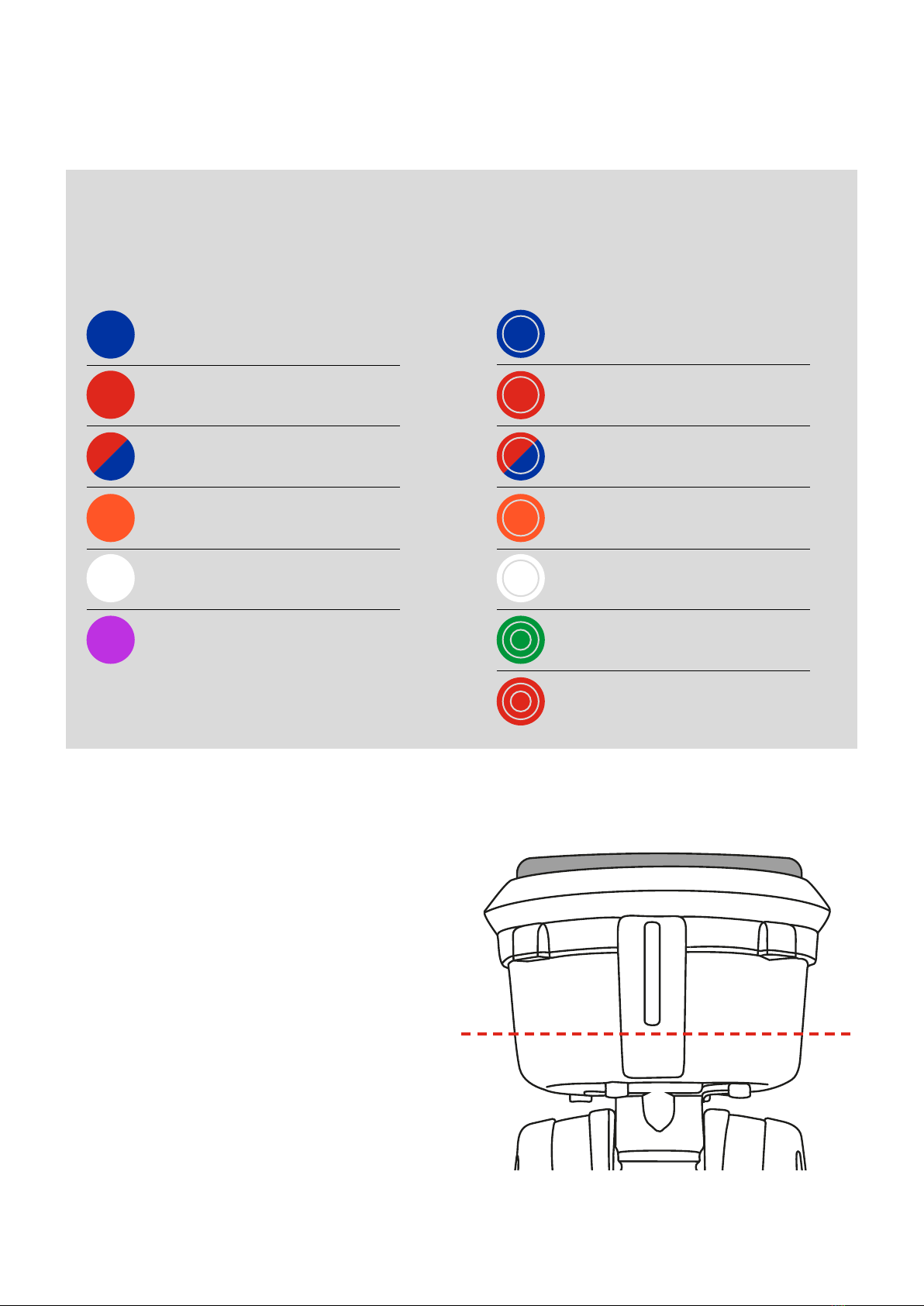
4.3LEDIndicatorReferenceChart
STATUS INDICATOR LEDS
SOLID BLUE FLASHING BLUE
SOLID RED FLASHING RED
ALTERNATE SOLID RED/BLUE FLASHING ALT RED/BLUE
SOLID ORANGE FLASHING ORANGE
SOLID WHITE FLASHING WHITE
SOLID PURPLE TRIPLE FLASHING GREEN
TRIPLE FLASHING RED
SMOKE TEST SMOKE TEST ACTIVE
WHEN IDLE WHEN ACTIVE
HEAT TEST HEAT TEST ACTIVE
COMBINED TEST COMBINED TEST ACTIVE
DELAYED START DELAYED START ACTIVE
CLEARING CLEARING ACTIVE
SYSTEM FAULT PASSED TEST RESULT
FAILED TEST RESULT
Testire XTR2 indicates events as follows:
Correct head angle adjustment is important to make sure that
the detector to be tested is correctly positioned within the
tester cup and that the user is in a safe and appropriate position
to carry out the test.
The detector should touch the base of the Testire XTR2
clear standoff and should be level with the base of the
detector (Fig. 7)
Adjust the head unit for the correct angle to access the
detector. Hold the body of Testire XTR2 and gently move
the cup forwards or backwards to the desired position.
4.4AdjustingtheHeadUnitAngle Figure7
12
Testire XTR2
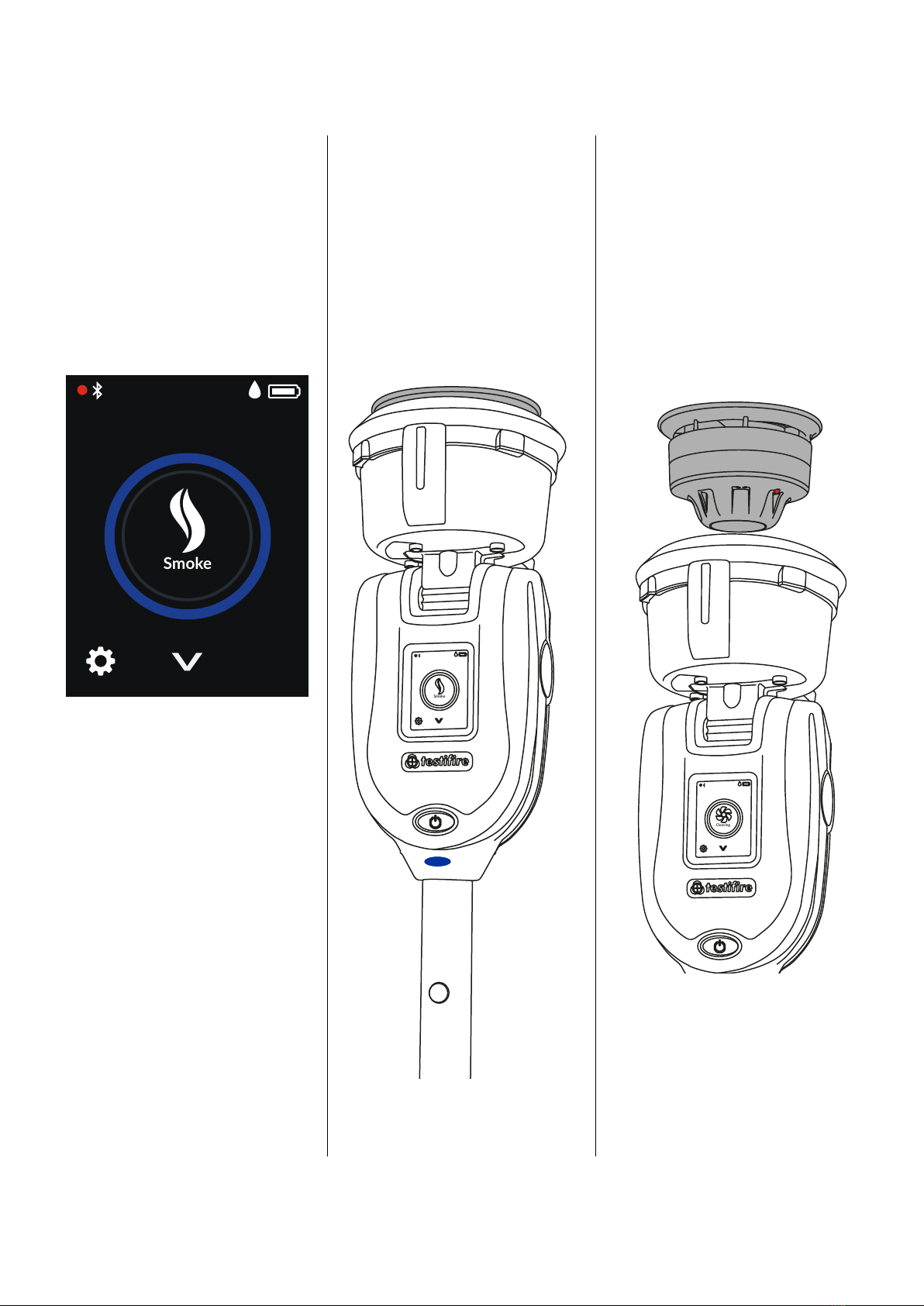
After you have completed the
preparation procedures your Testire
XTR2 will be ready for use.
When powered on, Testire XTR2 LCD
will be congured to perform a smoke
test by default. The smoke icon will
be visible on the LCD display and the
status LED’s will be solid blue (Fig. 8).
An infrared beam across the tester
cup controls the test.
The test will begin automatically
when the tester cup is placed over the
detector, breaking the infrared beam.
The status LED will ash blue to
indicate smoke is being generated
and the test started (Fig. 9).
When the detector is activated, the
optical LED reader inside the tester
cup will sense the detector activation
LED and automatically end the test.
The status LED’s will ash triple
green to indicate the test has been
successful and clearing mode will
begin automatically (see section 5.5).
To end clearing, remove Testire XTR2
by gently lowering it (Fig. 10).
PERFORMING A TEST
5.1 Default Smoke Test
5
Figure8 Figure9
Figure10
NOTE:
If after two minutes the test has not
completed, Testire XTR2 will time-out
and the test will be recorded as failed.
The status LED will ash triple red to
indicate the test has been unsuccessful
and you should remove Testire XTR2
by gently lowering it.
Smoke
Smoke
Clearing
13
Testire XTR2
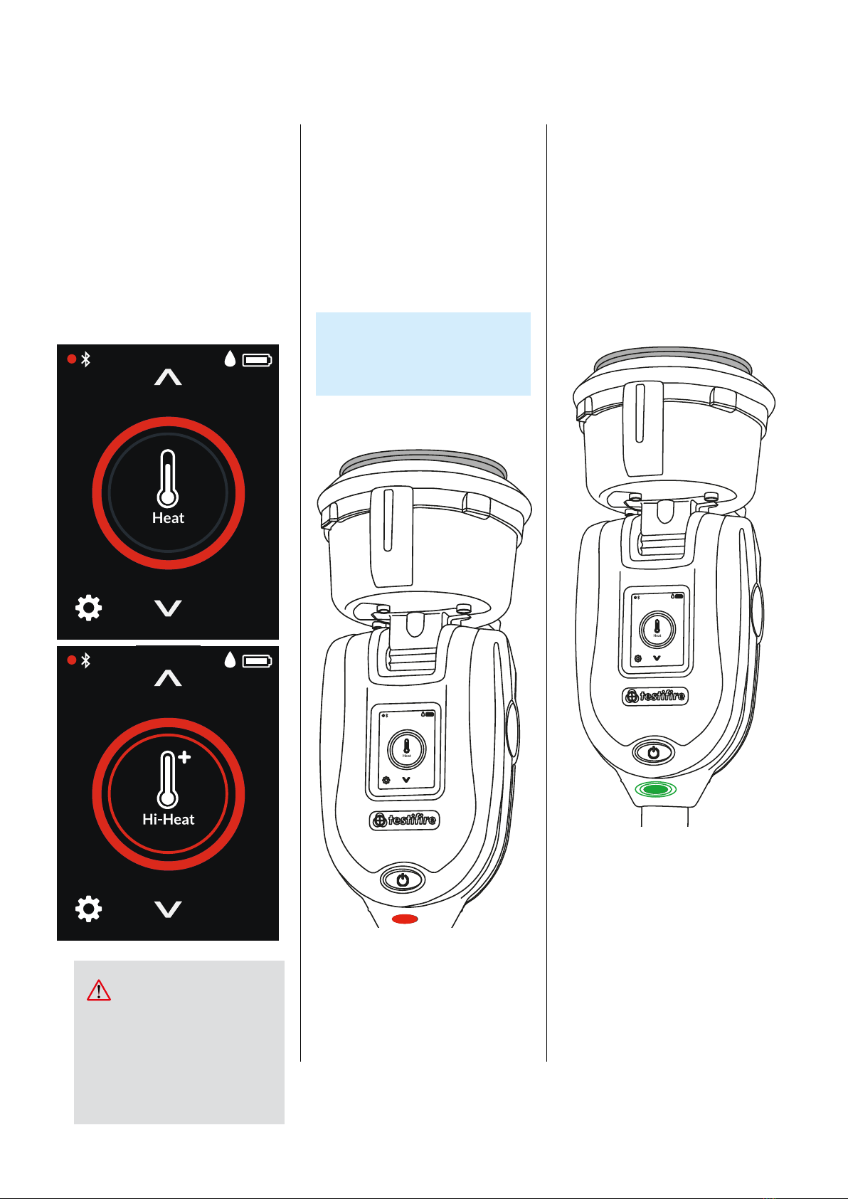
Select the heat function using the
navigation arrows on the LCD display.
Once selected, the heat icon will be
shown and the status LED will turn
solid red.
Once selected, tap the heat icon to
select the high heat function (Fig. 11)
An infrared beam across the tester
cup controls the test.
The test will begin automatically
when the tester cup is placed over the
detector, breaking the infrared beam.
The status LED will ash red to
indicate heat is being generated
and the test started (Fig. 12).
When the detector is activated, the
optical LED reader inside the tester
cup will sense the detector activation
LED and automatically end the test.
The status LED will ash triple
green to indicate the test has been
successful and you should remove
Testire XTR2 by gently lowering
it (Fig. 13).
5.2 Heat Test
Figure 11
Figure 12
Figure 13
NOTE:
If after two minutes the test has not
completed, Testire XTR2 will time-out
and the test will be recorded as failed.
The status LED will ash triple red to
indicate the test has been unsuccessful
and you should remove Testire XTR2
by gently lowering it.
TIP:
Rotating Testire around the
detector can speed up a test on
detectors with offset thermistors
Avoid placing hands near the
duct outlet during heat testing or
within 5 minutes of conducting
heat testing. Hot air is emitted
from the duct and the top of the
duct will get hot to the touch.
CAUTION
Heat
Heat
Heat
14
Testire XTR2
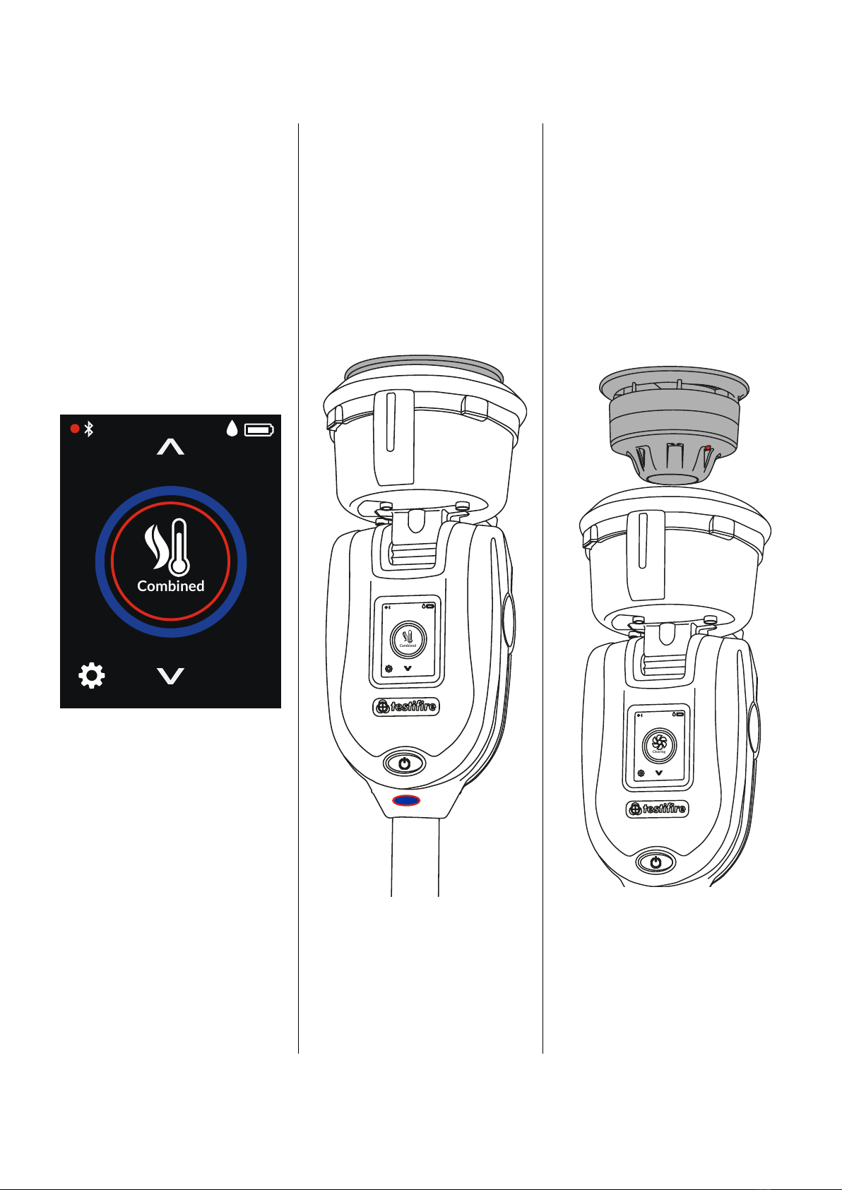
Using Testire XTR2 to carry out
combined testing means that a
number of operations (Smoke, Heat
and Clearing) can be pre-programmed
into the unit before it is raised up to
the detector. This saves time, reduces
handling and enables the testing of
certain multi-sensor detectors.
Select the Combined function using
the navigation arrows on the LCD
display. Once selected the status LED’s
will alternate between solid blue
and solid red (Fig. 14).
The test will begin automatically
when the tester cup is placed over the
detector, breaking the infrared beam.
When performing a combined test,
the status LED will ash blue and red
alternately to indicate both smoke
and heat are being generated
simultaneously (Fig. 15).
When the detector is activated, the
optical LED reader inside the tester
cup will sense the detector activation
LED and automatically end the test.
The status LED’s will ash triple
green to indicate the test has been
successful and clearing mode will
begin automatically (see section 5.5).
To end clearing, remove Testire
XTR2 by gently lowering it (Fig. 16).
5.3CombinedTest
Figure 14
Figure 15
Figure 16
NOTE:
If after two minutes the test has not
completed, Testire XTR2 will time-out
and the test will be recorded as failed.
The status LED will ash triple red to
indicate the test has been unsuccessful
and you should remove Testire XTR2
by gently lowering it.
Combined
Combined
Clearing
15
Testire XTR2
Using Testire XTR2 to carry out a
sequential test means that a
number of operations (Smoke, Heat
and Clearing) can be pre-programmed
into the unit before it is raised up to
the detector. This saves time, reduces
handling and enables the testing of
certain multi-sensor detectors.
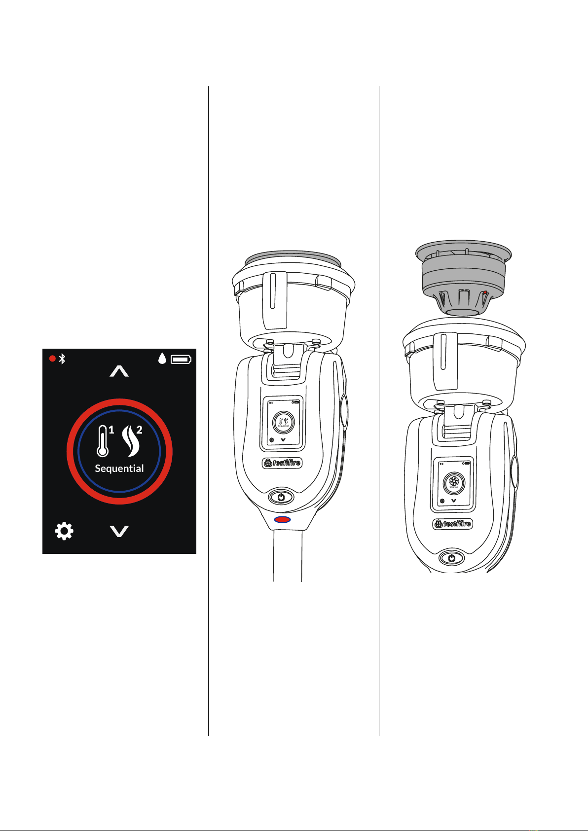
Select the Sequential function using
the navigation arrows on the LCD
display (Fig. 17). Once selected the
status LED’s will turn solid red to
identify the rst test in the sequence
as heat. Sequential tests follow the
following predened order:
The test will begin automatically
when the tester cup is placed over the
detector, breaking the infrared beam.
When the detector is activated, the
optical LED reader inside the tester
cup will sense the detector activation
LED and the next test mode will begin
automatically (Fig. 18).
Once the Sequential test is complete,
the status LED’s will ash triple
green to indicate the test has been
successful and clearing mode will
begin automatically (see section 5.5).
To end clearing, remove Testire XTR2
by gently lowering it (Fig. 19)
5.4 Sequential Test
Figure17
Figure18 Figure19
NOTE:
If after two minutes the test has not
completed, Testire XTR2 will time-out
and the test will be recorded as failed.
The status LED will ash triple red to
indicate the test has been unsuccessful
and you should remove Testire XTR2
by gently lowering it.
NOTE:
Lowering Testire XTR2 from the
detector during a sequential test will
terminate the test.
1. Heat
2. Smoke
3. Clearing
Sequential
Sequential
Clearing

16
Testire XTR2
Once activated any lingering smoke can be cleared from the
detector using the ‘Clearing mode’. Air is blown around the
detector – clearing any lingering smoke via the vent in the cup.
To perform clearing after a smoke, combined or sequential test,
continue to hold Testire XTR2 over the detector. If the test
was successful, clearing will begin automatically and the status
LED’s will ash white (Fig. 20).
On occasions, it may be necessary to test detectors that do not
easily t into the Testire XTR2 tester cup or are obstructed
in some way. To allow testing of such detectors or aspirating
smoke detection systems, Testire XTR2 has the facility to
delay the start of a test.
To use this function, use the navigation arrows on the LCD
menu until Delayed Start is displayed and tap the icon to begin
the timer (Fig. 21).
In low light levels, an LED torch will automatically illuminate
from inside the cup. This makes for easy alignment and testing
of detectors in dark environments.
Upon alignment and the starting of the test the LED torch
will switch off to allow a clear view of the status LED’s and to
enable the optical LED reader inside the tester cup.
To perform clearing on its own, download the Detectortesters
Connect app start a new Test Job:
1. Open the Detectortesters Connect app on your mobile
device
2. Pair your Testire XTR2 device and start a new test job
3. Select your test location and tap “next step”
4. Select the “Smoke” test mode and tap “Start Test”.
5. Tap the “Clearing” icon in the top right hand corner
The default timer for the Delayed Start function is 20 seconds
and can be adjusted using the Detectortesters Connect app.
1. Open the Detectortesters Connect app on your mobile
device
2. Pair your Testire XTR2 device and start a new test job
3. Select your test location and tap “next step”
4. Select the “ASD or Flat Detectors” test mode and tap “Start
Test”.
5. Choose from either 5, 20 or 40 seconds for the delayed
start and tap “Start Test”
5.5 Clearing a Detector 5.6 Delayed Start
5.7UsingtheLEDTorch
Figure20 Figure 21
NOTE:
Automatic clearing does not occur following an
unsuccessful test.
NOTE:
See section 8 for more information on using Testire XTR2
with the Detectortesters Connect app.
Clearing
Delayed
Start

17
Testire XTR2
A manual purge may be required when the unit has not been
used for a period of time, when in cold conditions, a new
generator has been installed or in the case of a signicant
drop in performance. A manual purge should be carried out
in a well ventilated.
Select the Settings icon from the bottom left corner of the LCD
display and then select Purge. Tap the icon to begin the Purge
function (Fig. 22).
5.8ManualPurge 5.9DeviceSettings
Figure 22
Figure 23
A manual purge can also be performed from the Detectortesters
Connect app as follows:
1. Open the Detectortesters Connect app on your mobile device
2. Pair your Testire XTR2 device and start a new test job
3. Select your test location and tap “next step”
4. Select the “Smoke” test mode and tap “Start Test”.
5. Tap the “Clearing” icon in the top right hand corner
NOTE:
See section 8 for more information on using Testire XTR2
with the Detectortesters Connect app.
The device settings can be viewed by pressing the cog icon on
your Testire XTR2 display (Fig. 23). From this menu you can
view the following settings:
1. Device information – including model, serial number, rmware
version, battery serial number Bluetooth MAC address
2. Alarm detection mode – to choose if the optical LED reader
responds to solid or ashing detector LED’s
3. Bluetooth settings – to access Bluetooth QR code for pairing
with mobile devices
4. Purge – to perform a manual purge of the smoke generator
(see section 5.8)
Purge
Purge
Sengs
Purge
Bluetooth
Alarm Detection
Device Information

18
Testire XTR2
ASD ADAPTOR – TESTING ASD SYSTEMS
AND FLAT DETECTORS
6
ASD systems and Flat Detectors can be tested using the
Delayed Start mode and changing the tester membrane to the
ASD Adaptor (Product Code: TESTIFIREADAP-001).
Users should note that using Testire XTR2 in this congura-
tion is outside the scope of UL classication for Testire XTR2.
The application has been thoroughly tested independently with
all ASD technologies and a wide range of Flat Detectors.
1. Ensure Testire XTR2 is powered off
2. Remove the Testire XTR2 membrane (see section 7.7)
3. Attach the ASD adaptor, stretching it over the tester
cup and ensuring the tongues align with the relevant
grooves in the tester cup (Fig. 24).
1. Power on Testire XTR2
2. Select the Delayed Start mode by using the navigation
arrows on the LCD display.
3. Tap the Delayed Start icon to begin the timer. During
the timer the status LED’s will ash orange
4. Locate Testire XTR2 over the sampling hole. Smoke
will automatically be generated for 20 seconds indicat-
ed by the status LED’s ashing blue (Fig. 25).
6.1 Testing an ASD System or Flat Detectors
6.2InstallingtheASDAdaptor
6.3TestingwiththeASDAdaptor
Figure 24
Figure 25
NOTE:
The delayed start timer is set to a 20 second by default and
can be congured via the Detectortesters Connect App (see
section 5.6).

19
Testire XTR2
REMOVING AND REPLACING
CONSUMABLES
7
All consumable parts of Testire XTR2 can be replaced in the
eld without having to return the unit for service.
Ensure that the unit is switched off during the replacement of
consumables. Do not touch electrical contacts.
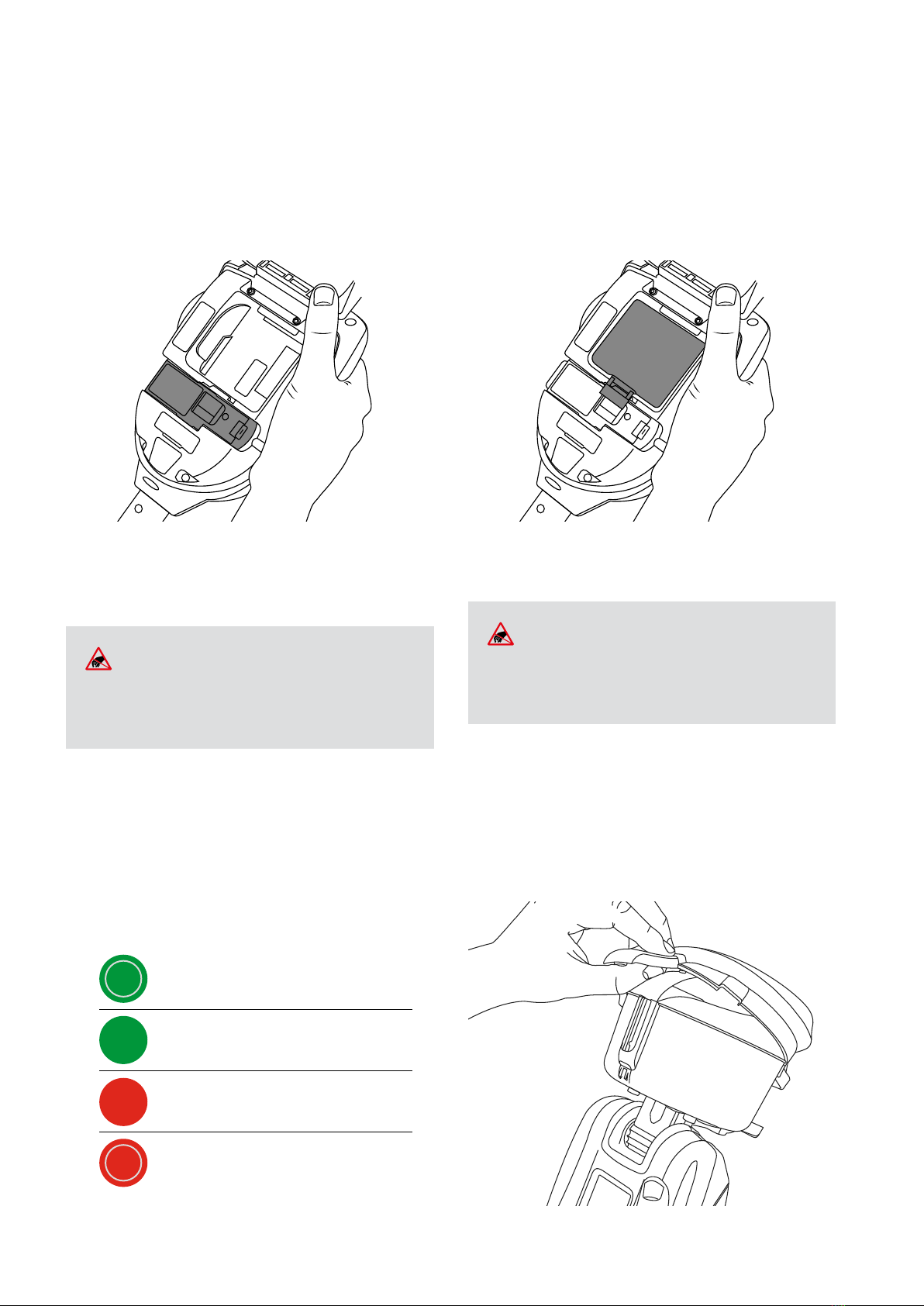
1. Ensure the unit is switched off and open the back cover
2. Remove the smoke cartridge from the generator by
placing your thumb in the recess and sliding the car-
tridge along the guide rails (Fig. 26). Do not remove the
Generator
1. Remove the Cartridge from the bag
2. Slide the cartridge completely into the generator housing
following the guide rails (Fig. 27)
3. Once the cartridge is inserted into the generator do not
remove it until indicated that a replacement is necessary
on the LCD display or in the Detectortesters Connect app
7.1RemovingtheSmokeCartridge
7.2ReplacingtheSmokeCartridge
Figure 26
Figure27
NOTE:
Do not re-use empty cartridges. Empty cartridges may
be returned to the manufacturer via the reseller for
environmentally friendly disposal to comply with WEEE
(Waste Electrical & Electronic Equipment) Regulations.
NOTE:
When replacing the generator, any dust or debris within the
housing can be removed using an air duster. Condensation
can be removed by wiping with a lint-free cloth.
Do not touch the contacts on the cartridge. Static
electricity may cause damage and contamination of
the contacts must be avoided.
WARNING
1. Ensure the unit is switched off and the Smoke Cartridge
is removed (section 7.1)
2. Disengage Clip 1 and lift. Repeat for Clip 2 to remove
the used generator (Fig. 28)
7.3RemovingtheSmokeGenerator
Figure28
2
1
20
Testire XTR2
1. Insert the generator rmly into the recess, engaging clips
1 and 2 (Fig. 29)
1. Ensure the unit is switched off and open the back cover.
2. Unclip and remove the battery
3. Insert the battery into the charge cradle
4. Charge the battery by connecting the USB-C lead to the
charge cradle and the supplied mains power adaptor or
car adaptor (see Section 3.1)
7.4ReplacingtheSmokeGenerator
7.5RemovingtheBatteryforCharging
Figure29
NOTE:
Once the generator is inserted do not remove it until
indicated that a replacement is necessary on the LCD
display or in the Detectortesters Connect app.
Do not touch the contacts on the generator. Static
electricity may cause damage and contamination of
the contacts must be avoided.
WARNING
FLASHING GREEN
SOLID GREEN
SOLID RED
FLASHING RED
BATTERY CHARGING
BATTERY FULLY CHARGED
NO BATTERY CONNECTED
BATTERY FAULT
CHARGE CRADLE STATUS LED COLOUR
1. Once the battery is charged gently clip it into the battery
compartment and close the back cover (Fig. 30)
1. Ease the membrane off the tester cup carefully
2. Take the replacement membrane and stretch it over the
tester cup. Ensure the membrane tongues align with the
relevant grooves in the tester cup (g. 31)
7.6ReplacingtheBattery
7.7RemovingandReplacingtheMembrane
Figure30
Figure 31
NOTE:
Do not force the battery into place.
Do not touch the contacts on the battery or charge
cradle. Static electricity may cause damage and
contamination of the contacts must be avoided.
WARNING
Other manuals for testifire XTR2
1
Table of contents
Other Detectortesters Test Equipment manuals


