PI L-220 User manual

PI miCos GmbH, Freiburger Strasse 30, 79427 Eschbach, Germany
Phone +49 7634 5057-0, Fax +49 7634 5057-99, Email info@pimicos.de, www.pi.ws
MP149E
L
-220 Linear Actuator
User Manual
Version: 1.3
Date: 2020-11-13
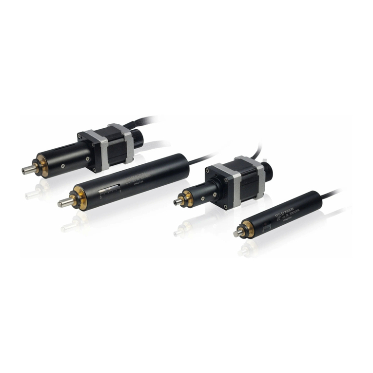
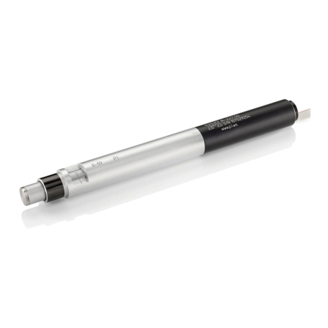
This document describes the following high
-
resolution linear actuators:
L-220.10DG
DC drive with gearhead,
travel range 13 mm (0.5")
L-220.10SG
Stepper motor drive with gearhead,
travel range 13 mm (0.5")
L-220.20DG
DC drive with gearhead,
travel range 26 mm (1")
L-220.20SG
Stepper motor drive with gearhead,
travel range 26 mm (1")
L-220.50DG
DC drive with gearhead,
travel range 52 mm (2")
L-220.50SG
Stepper motor drive with gearhead,
travel range 52 mm (2")
L-220.70DG
DC drive with gearhead,
travel range 77mm (3")
L-220.70SG
Stepper motor drive with gearhead,
travel range 77mm (3")

The following company names and brands are registered trademarks of
Physik Instrumente (PI) GmbH & Co. KG:
PI®, NanoCube®, PICMA®, PIFOC®, PILine®, NEXLINE®, PiezoWalk®, PicoCube®, PiezoMove®, PIMikroMove®,
NEXACT®, Picoactuator®, PInano®, NEXSHIFT®, PITOUCH®, PIMag®, PIHera, Q-Motion®
© 2020 Physik Instrumente (PI) GmbH & Co. KG, Karlsruhe, Germany. The text, photographs, and drawings in
this manual are protected by copyright. With regard thereto, Physik Instrumente (PI) GmbH & Co. KG reserves
all rights. The use of any text, images and drawings is permitted only in part and only when indicating the
source.
Original instructions
First printing: 13.11.2020
Document number: MP149E, MMa, Version 1.3
Subject to change without notice. This manual is superseded by any new release. The latest release is
available for download from our website.

1About this Document 1
1.1 Objective and Target Group of this User Manual ...................................................... 1
1.2 Symbols and Typographic Conventions...................................................................... 1
1.3 Definition of Terms..................................................................................................... 2
1.4 Further Applicable Documents................................................................................... 2
2Safety 3
2.1 Intended Use .............................................................................................................. 3
2.2 General Safety Instructions ........................................................................................ 3
2.2.1 Organizational Measures............................................................................... 4
3Product Description 5
3.1 Model Overview ......................................................................................................... 5
3.2 Product View .............................................................................................................. 6
3.3 Direction of motion .................................................................................................... 7
3.4 Product Labeling......................................................................................................... 7
3.5 Scope of Delivery........................................................................................................ 8
3.6 Suitable Controllers .................................................................................................... 8
3.7 Technical Features...................................................................................................... 9
3.7.1 Rotary Encoder .............................................................................................. 9
3.7.2 Limit Switches................................................................................................ 9
3.7.3 Reference Point Switch.................................................................................. 9
4Unpacking 11
5Installation 13
5.1 General Notes on Installation................................................................................... 13
5.2 Providing a Suitable Mechanical Mounting and Installation Environment.............. 13
5.3 Installing the Linear Actuator in a Mechanical Mounting ........................................ 15
5.4 Mounting a Tip ......................................................................................................... 16
5.5 Changing the Tip....................................................................................................... 18
6Start-Up 19
6.1 General Notes on Start-Up....................................................................................... 19
6.2 Starting up the Linear Actuator................................................................................ 21
6.2.1 L-220 Entries in the Stage Database of PI.................................................... 21
Contents

7Maintenance 23
7.1 Performing a Maintenance Run ............................................................................... 23
7.2 Cleaning the L-220.................................................................................................... 24
8Troubleshooting 25
9Customer Service 27
10 Technical Data 29
10.1 Specifications............................................................................................................ 29
10.1.1 Data Table.................................................................................................... 29
10.1.2 Maximum Ratings........................................................................................ 30
10.1.3 Ambient Conditions and Classifications ...................................................... 31
10.1.4 Limit Switch Specifications .......................................................................... 31
10.1.5 Reference Point Switch Specifications ........................................................ 31
10.2 Dimensions ............................................................................................................... 32
10.2.1 Linear Stage ................................................................................................. 32
10.2.2 Tips............................................................................................................... 33
10.3 Pin Assignment ......................................................................................................... 34
10.3.1 HD Sub-D 26 (m) .......................................................................................... 34
10.4 Tightening Torque for Screws, ISO 4762 - A2........................................................... 36
11 Old Equipment Disposal 37
12 EU Declaration of Conformity 39

1 About this Document
L-220 Linear Actuator MP149E Version: 1.3 1
1.1 Objective and Target Group of this User Manual
This user manual contains the necessary information on the intended use of the L-220.
Basic knowledge of closed-loop systems, motion control concepts, and applicable safety
measures is assumed.
The latest versions of the user manuals are available for download on our website (p. 2).
1.2 Symbols and Typographic Conventions
The following symbols and typographic conventions are used in this user manual:
CAUTION
Dangerous situation
If not avoided, the dangerous situation will result in minor injury.
Actions to take to avoid the risk.
NOTICE
Dangerous situation
If not avoided, the dangerous situation will result in damage to equipment.
Actions to take to avoid the risk.
INFORMATION
Information for easier handling, tricks, tips, etc.
Symbol/
Label
Meaning
1.
2.
Action consisting of several steps whose sequential order must be
observed
Action consisting of one or several steps whose sequential order is
irrelevant
Lists
p. 5 Cross-reference to page 5
1
About this Document

1 About this Document
2 Version: 1.3 MP149E L-220 Linear Actuator
1.3 Definition of Terms
Term Explanation
Load capacity Maximum load capacity in the vertical direction when the linear
actuator is mounted horizontally. The contact point of the load is at
the center of the motion platform.
Max. push/pull force Maximum force in the direction of motion. Some stages may have
higher forces but with limited lifetimes. In the case of vertical
mounting, the specified value (s. 29) for models without a gearhead
and brake only applies when the servo mode is on.
Rotary encoder The rotary encoder is a sensor for capturing changes in position.
Signals from the sensor are used for axis position feedback. After the
controller is switched on, a reference point definition must be
performed before absolute target positions can be commanded and
reached.
1.4 Further Applicable Documents
The devices and software tools from PI that are mentioned in this documentation are described
in separate manuals.
Product Document
L-220 MP159EK Short instructions for
L-2xx/MA-35/MP-20/MP-15 linear actuators
C-863.12 * MS249E User manual
C-663.12* MS241E User manual
C-884* MS243E User manual
C-885** C885T0002 User manual
C-663.12C885* C663T0004 User manual
C-863.20C885* C863T0005 User manual
C-885* C885T0002 User manual
C-663.12C885* C663T0004 User manual
SMC Hydra Technisches Benutzerhandbuch SMC Hydra
(SMC-Hydra CM TT.doc)
* Depending on the ordered controller. Further documents included in the data carrier(s)
provided with the controller.

2 Safety
L-220 Linear Actuator MP149E Version: 1.3 3
2.1 Intended Use
The L-220 is a laboratory device as defined by DIN EN 61010-1. It is intended for indoor use and
use in an environment which is free of dirt, oil, and lubricants.
In accordance with its design, the L-220 is intended for single-axis positioning, adjusting and
shifting of loads at various velocities.
The intended use of the L-220 is only possible when installed and in conjunction with a suitable
controller. The controller is not included in the scope of delivery of the L-220.
2.2 General Safety Instructions
The L-220 is built according to state-of-the-art technology and recognized safety standards.
Improper use of the L-220 may result in personal injury and/or damage to the L-220.
Only use the L-220 for its intended purpose, and only use it if it is in good working
order.
Read the user manual.
Immediately eliminate any faults and malfunctions that are likely to affect safety.
The operator is responsible for the correct installation and operation of the L-220.
2
Safety

2 Safety
4 Version: 1.3 MP149E L-220 Linear Actuator
2.2.1 Organizational Measures
User manual
Always keep this user manual available when using the L-220.
The latest versions of the user manuals are available on our website (p. 2) for
download.
Add all information from the manufacturer such as supplements or technical notes to
the user manual.
If you give the L-220 to other users, also include this user manual as well as all other
relevant information provided by the manufacturer.
Only use the device on the basis of the complete user manual. Missing information due
to an incomplete user manual can result in minor injury and damage to equipment.
Only install and operate the L-220 after you have read and understood this user
manual.
Personnel qualification
The L-220 may only be installed, started up, operated, maintained, and cleaned by authorized
and appropriately qualified personnel.

3 Product Description
L-220 Linear Actuator MP149E Version: 1.3 5
3.1 Model Overview
There are six standard versions of the L-220. All models are high-resolution linear actuators with
a limit switch. They differ with respect to:
Drive type
Travel range
Model Travel range Drive type
13 mm 26 mm 52 mm 77 mm DC gear
motor
Step
gear motor
L-220.10DG + +
L-220.10SG + +
L-220.20DG + +
L-220.20SG + +
L-220.50DG + +
L-220.50SG + +
L-220.70DG + +
L-220.70SG + +
Detailed model overview
Order number Product name
L-220.10DG High-resolution linear actuator, DC gear motor, 13 mm (0.5") travel
range, magnetic limit switches
L-220.10SG High-resolution linear actuator, stepper motor with gearhead, 13 mm
(0.5") travel range, magnetic limit switches
L-220.20DG High-resolution linear actuator, DC gear motor, 26 mm (1") travel range,
magnetic limit switches
L-220.20SG High-
resolution linear actuator, stepper motor with gearhead, 26 mm (1")
travel range, magnetic limit switches
L-220.50DG High-resolution linear actuator, DC gear motor, 52 mm (2") travel range,
magnetic limit switches
L-220.50SG High-
resolution linear actuator, stepper motor with gearhead, 52 mm (2")
travel range, magnetic limit switches
3
Product Description

3 Product Description
6 Version: 1.3 MP149E L-220 Linear Actuator
L-220.70DG High-resolution linear actuator, DC gear motor, 77 mm (3") travel range,
magnetic limit switches
L-220.70SG High-
resolution linear actuator, stepper motor with gearhead, 77 mm (3")
travel range, magnetic limit switches
For further technical data, see the specifications (p. 29).
PI also produces custom versions upon request. Custom versions can differ from the described
standard products in respect to dimensions, characteristics or other technical data.
If necessary, contact our customer service department directly (p. 27).
3.2 Product View
Figure 1: Parts of the L-220 (here with flat tip)
1
Tip, replaceable (here: Flat, mounted on pusher)
2Thread for clamp connection
3Mounting nut for clamp connection
4Smooth cylinder surface, e.g., for mounting in a hole
5Sleeve
6Cable
7Controller connection (HD Sub-D 26, male)

3 Product Description
L-220 Linear Actuator MP149E Version: 1.3 7
3.3 Direction of motion
Figure 2: Direction of motion of the pusher (her with flat tip)
X (arrow direction:) Direction of motion on positive command
3.4 Product Labeling
Figure 3: Product labeling
Position Labeling Description
1, 3
Manufacturer's logo
2 L-220 Product series
3 L-220.20SD00 Product name (example), the characters after the
period refer to the model
3 415002159 Serial number (example), individual for each L-220
Meaning of the places (counting from left): 1 =
internal information, 2 and 3 = year of manufacture, 4
to 9 = consecutive numbers
3
Warning sign "Observe manual!"
3 Country of origin: Germany Country of origin
3
CE conformity mark
3 WWW.PI.WS Manufacturer's address (website)
3
Old equipment disposal
4*
Warning sign "Electrostatic sensitive devices"
* also on the opposite side of the connector

3 Product Description
8 Version: 1.3 MP149E L-220 Linear Actuator
3.5 Scope of Delivery
Order number Component
L-220 Linear actuator according to order (p. 5), with flat tip and spherical tip (not
mounted on delivery)
MP159EK Short instructions for L-2xx/MA-35/MP-20/MP-15 linear actuators
K3110154
UNC bolt for adaptation to a connector of an extension cable (2 units)
3.6 Suitable Controllers
The L-220 must be connected to a suitable controller. The following controllers from PI are
suitable for the operation of the L-220:
Stage Controller Axes per
controller
PC
interface
Multiple
controllers on
the same PC
L-220.x0DG
C-863 1 USB, RS-232,
daisy chain
network
Yes, same
interface
C-884 1 to 4 USB, RS-232,
TCP/IP
Yes
L-220.x0SG
C-663.12
1
USB, RS-232,
daisy chain
network
Yes, same
interface
The required PC software is included in the scope of delivery of the controllers from PI. The
operation of the controllers is described in the corresponding user manuals.
The operating parameters must be adjusted depending on the version of the L-220 used.

3 Product Description
L-220 Linear Actuator MP149E Version: 1.3 9
3.7 Technical Features
3.7.1 Rotary Encoder
The models with DC motors are equipped with a rotary encoder. A rotary encoder, also called
an incremental or incremental rotary encoder, is implemented at a rotating point in the
drivetrain, e.g., the motor shaft. To determine the relative position, the controller counts the
encoder signals, the so-called impulses.
3.7.2 Limit Switches
The L-220 is equipped with noncontact, Hall-effect limit switches.
Each limit switch sends its signal to the controller on a dedicated line. The controller then stops
the motion. If the controller does not stop the motion in time, the linear actuator runs into the
hard stop.
See "Limit Switch Specifications" for more information (p. 31).
3.7.3 Reference Point Switch
The L-220 is equipped with one direction-sensing reference point switch that is located at about
the midpoint of the travel range. This sensor transmits a TTL signal that indicates whether the
linear actuator is on the positive or negative side of the reference point switch.
See the controller user manual and/or associated software manuals for the commands that
make use of the reference point signal.
For more information, see "Reference Point Switch Specifications" (p. 31).


4 Unpacking
L-220 Linear Actuator MP149E Version: 1.3 11
1. Unpack the L-220 with care.
2. Compare the contents with the items listed in the contract and the packing list.
3. Inspect the contents for signs of damage. If there is any sign of damage or missing parts,
contact PI immediately.
4. Keep all packaging materials in case the product needs to be returned.
4
Unpacking


5 Installation
L-220 Linear Actuator MP149E Version: 1.3 13
5.1 General Notes on Installation
NOTICE
Cable break!
A cable break leads to failure of the linear actuator.
Install the linear actuator so that the cable is not bent too strongly or crushed.
NOTICE
Increased friction!
Lateral forces that act on the pusher of the linear actuator increase the friction of the
internal drive components. Increased friction impairs the motion of the pusher and
increases wear on the drive components.
Avoid lateral forces on the tip and on the pusher of the L-220.
NOTICE
Heating up of the L-220 during operation!
The heat produced during operation of the L-220 can affect your application.
Install the L-220 so that the application is not impaired by the dissipated heat.
INFORMATION
Models with DC gear motors are equipped with integrated signal drivers for cable lengths
≤10m between the linear actuator and the motor controller
5.2 Providing a Suitable Mechanical Mounting and Installation
Environment
A suitable mechanical mounting and installation environment are necessary for the proper use
of the actuator.
Make sure that the following conditions have been met:
−Material and statics of the mounting are designed so that the static and dynamic
forces that occur can be safely and continuously managed.
5
Installation

5 Installation
14 Version: 1.3 MP149E L-220 Linear Actuator
−The dimensions of the mounting are adapted to the dimensions of the actuator (see
above figures and dimensions (p. 32)).
−The intended motions of the pusher and the load must not be inhibited by the
dimensions of the installation environment.
Take into account the following specifications as well when planning the application
and installing the actuator:
−Dimensions of the tip selected (see Dimensions (p. 32))
−Travel range: (see data table (p. 29))
−Space requirements for a kink-free and proper guiding of the connecting cable and
additional motor cables
−Length of the connection cable and the motor cable
If the limit switches of the actuator cannot be reached with the planned minimum and
maximum displacements: Make sure that the actuator and the load only move within
the planned range. Suitable measures:
−Corresponding programming of the controller
−Emergency off switch
−Automatic shutdown systems
Avoid or label danger areas that result from the installation of the actuator and from
use, in accordance with the legal regulations (e.g. risk of crushing in the case of heavy
moving loads, fast actuator motions and/or high drive torques).
The complete dimensions of the actuator and relevant individual parts can be found in the
figures in the section Dimensions (p. 32).

5 Installation
L-220 Linear Actuator MP149E Version: 1.3 15
5.3 Installing the Linear Actuator in a Mechanical Mounting
NOTICE
Incorrect tightening torque of the mounting nut!
The motion of the pusher can be hindered by a mounting nut that has been tightened too
strongly. This reduces the positioning accuracy.
Tighten the mounting nut to a maximum torque 10 Nm.
INFORMATION
To achieve an optimum repeatability, the mounting shaft must not have any backlash.
During mounting, make sure that there is a faultless connection between the actuator and the
mechanical mounting.
Figure 4: Clamp connection (schematic)
1Mechanical mounting
2Sleeve
3Mounting nut
4Mounting shaft with thread
5Pusher
We recommend installing the actuator in the mechanical mounting with a clamp connection.
The following instructions refer to this case.
Requirements
You have read and understood the general notes on installation (p. 13).
You have provided your application with a suitable mounting for the mounting shaft of
the actuator.
The tip is not mounted on the actuator.

5 Installation
16 Version: 1.3 MP149E L-220 Linear Actuator
Tools and accessories
Open-end wrench AF 17
Installing the actuator
1. Loosen the mounting nut on the mounting shaft of the actuator.
2. Position the actuator in the mounting of your application.
3. If necessary, put a suitable flat washer or a suitable spring washer on the mounting
shaft.
4. Manually screw the mounting nut into the thread of the mounting shaft with a few
rotations.
5. To clamp the actuator in the mounting, tighten the mounting nut using the open-end
wrench until you feel a resistance. The torque may not exceed 10 Nm!
6. Check that the actuator is affixed firmly in the mounting.
5.4 Mounting a Tip
NOTICE
Damage of the mechanics from torques at the tip
Avoid generation of torques when mounting or changing the tip.
INFORMATION
The supplied tips make it possible to realize different mechanical connections to a load:
A flat tip allows a wide-area connection to a load.
A spherical tip allows a punctiform connection to a load.
To achieve optimum repeatability:
Use a tip.
Make sure that the selected tip is completely screwed in and does not have any backlash.
The tip is used to establish contact with the load. On delivery, the tip is not preassembled.
The scope of delivery includes a tip with flat and hemispherical contact surfaces. An M6 inner
thread is provided for mounting the tip in the pusher.
Requirements
You have read and understood the general notes on installation (p. 13).
The pusher has been moved out so that you can easily reach the tip.
In the delivery state, the pusher is moved out.
This manual suits for next models
8
Table of contents
Other PI Controllers manuals
Popular Controllers manuals by other brands

Converging Systems
Converging Systems ILC-100 Series quick start guide

dixell
dixell Emerson iChill IC100CX EVO Quick reference guide

Pelltech
Pelltech DK8002A1 instruction manual

LSI
LSI MegaRAID SATA 300-8XLP Quick installation guide

Dantel
Dantel PointMaster TL1 installation guide

SpaGuts
SpaGuts VS300FC5 installation instructions