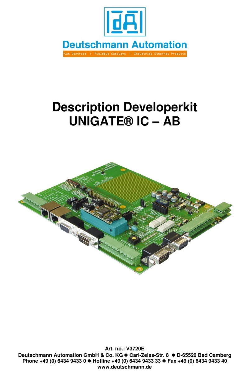
DEUTSCHMANN AUTOMATION UNIGATE FC Operating and installation instructions

Deutschmann Automation GmbH & Co. KG
2 Description Developerkit UNIGATE®FC V1.0 15.08.2012

Deutschmann Automation GmbH & Co. KG
15.08.2012 Description Developerkit UNIGATE®FC V1.0 3
These instructions will help you to easily and quickly start up your Developerkit
UNIGATE®FC.
PLEASE NOTE EVERY TIME BEFORE STARTING:
Image 1
Image 2
Image 3
NOTE: When using the application interface RS232, the sliding switch “Appl.” (Image 1)
must be set at RS422/RS232.
Insert the UNIGATE®FC (direction – observe image 2) and switch on the power supply -
POWER = ON (Image 3)
ATTENTION : The FC must never be inserted the wrong way round in the socket!
see chapter 5 for more detailed function descripion !

Deutschmann Automation GmbH & Co. KG
4 Description Developerkit UNIGATE®FC V1.0 15.08.2012
1. The Developerkit contains :
●1 x V3852 Developerboard UNIGATE®FC
●1 x V3719 Developerkit power supply unit
4 pole screw-/plug-connector (POWER)
1 9V-33V
2 0V
3 0V
4 PE
Colour
Signal
4 pole screw-/
plug-connector
White
+UB
1
Black
GND
2
Blue
GND
3
Blue
PE
4
Power unit 12V

Deutschmann Automation GmbH & Co. KG
15.08.2012 Description Developerkit UNIGATE®FC V1.0 5
●1 x V3719-A Developerkit serial cable (connection cable COM <-> Developerboard UNIGATE®
FC)
9 pole D-Sub 7 pole screw-/plug-connector (Appl. RS232)
Rx 2 1 Rx
Tx 3 2 Tx
GND 5 3 GND
●1 x V3719-B Developerkit debug cable (connection cable COM <-> Developerboard UNIGATE®
FC debug)
9 pole D-Sub 3 pole screw-/plug-connector (Debug RS232)
Rx 2 1 Rx
Tx 3 2 Tx
GND 5 3 GND
●1 x V3719-C Developerkit application cable (connection cable application RS422/485 <->
Developerboard UNIGATE®FC)
When using the RS422 or RS485 interface, please connect one end of the cable V3719-C with
your application and the other end via the 7 pole screw-/plug-connector of the serial cable
(V3719-A) with the Developerboard UNIGATE®FC.
Attention: Please always use only one of the 3 application interfaces!
●1 x V5001 USB cable 1 m
The USB cable connects the Developerboard with the PC (1st Appl. RS and 2nd Debug RS).
Alternative of V3719-A (Appl. RS232) and V3719-B (Debug RS232)!
ATTENTION: the external supply (e. g. power supply unit V3719) is imperative. Supply
via USB is insufficient.
●as well as documentation, a screwdriver and a Support CD, that contains all required software,
such as the RS232 monitor or the Protocol Developer, for simple creation of a Script for
UNIGATE®FC.
9 pole
D-Sub
female
Board FC
1.80 m
PC
9 pole
D-Sub
female
Board FC
1.80 m
PC
1.80 m

Deutschmann Automation GmbH & Co. KG
6 Description Developerkit UNIGATE®FC V1.0 15.08.2012
2. Accessories:
You can obtain a Master simulation of the Fieldbus side as an Add-on for the Developerkit
(separately for each Fieldbus). In addition to the appropriate Fieldbus adapter, you can also
receive the required connecting cable. PC software for the presentation of Fieldbus data, as well
as documentation.
3. Quick start:
4. Software:
-Installation Starterkit Software [Support CD]: Software\Starterkit\SetupStarterkit2.exe
After completion of installation, the Help file “starterkithelp.chm” for the next steps can be
found in the folder “Starterkit”.
-Installation Protocol Developer [Support CD]: Software\ProtocolDeveloper\ SetupPD.exe
After completion of installation, the Help file “ProtocolDeveloper.chm” for the next steps can be
found in the folder “Protocol Developer”.

Deutschmann Automation GmbH & Co. KG
15.08.2012 Description Developerkit UNIGATE®FC V1.0 7
5. Overview Developerboard UNIGATE®FC:
Slot UNIGATE®FC:
Note the direction. RJ45-socket of the UG-FC module
in direction of the edge of
the board.
ATTENTION: The UNIGATE®FC must never be inserted the wrong way
into the socket!
Sliding switch POWER ON/OFF and 3,3V-LED:
At Power ON the POWER-LED and the 3.3V-LED are illuminated.
Slide switch Appl. RS422, RS232/RS485:
This switch is required for setting of the serial (application) interface. The
switch can be used to switch between a RS422 and a RS485 interface. This is
the interface upon which the customer equipment is connected.
Sliding switch termination Appl. RS422/RS485:
Both of these switches are only relevant when the application interface is an
RS422 or RS485. Then the termination of the RS422 (both switches) or the
RS485 Bus (lower switch) can be connected via these switches.
USB pin-and-socket connector:
The board is connected to the PC via this plug-in connector. Thus, access is
provided to the 2 series interfaces (Appl. RS232 and Debug RS232) via 2 virtual
COM interfaces. A status LED indicates the USB connection.
Installation USB Driver [Support CD]: \Support\USB\Driver:
Two additional COM ports are available on your PC after installation. One port is
connected with the application interface, the other with the board’s debug
interface.
NOTE: the external supply (e.g. power supply unit V3719) is imperative
Supply via USB is insufficient.
Sliding switch mode Config/Run:
The UNIGATE®FC starts in configuration mode when set in “Config” position
during the PowerUp or Reset.
The “Run” position is the normal operating mode in which the UNIGATE®FC
runs the imported Script. An LED indicates the respectively set mode.
NOTE: In order to be able to use the configuration mode with the
software tools from Deutschmann, the PC must be connected with the
interface “Appl.RS232”.
Reset key:
A UNIGATE®FC reset is activated by pressing the reset key.
The red reset LED lights up each time the key is pressed.

Deutschmann Automation GmbH & Co. KG
8 Description Developerkit UNIGATE®FC V1.0 15.08.2012
Boot jumper (without jumper):
The UNIGATE®FC can be put in the firmware update mode via this jumper. In
order to do this, the jumper must be set during the PowerUp or Reset – the
red boot LED lights up.
NOTE: In order to be able to use the firmware update mode, the PC
must be connected with the interface “Appl.RS232”.
Pin strip IN1 – IN16:
Input shift register. The first 16 digital inputs of the shift register are
available, each provided with an LED
Rotary switch IN17 – IN24:
Input shift register. 8 digital inputs (17-24) of the shift register are available
here via rotary code switches (i. e. the “High” and “Low” switches can be read
in via the shift register), each provided with an LED.
DIP-switch IN25 – IN32:
Input shift register. 8 digital inputs (25-32) of the shift register are available
here via a DIP switch (i.e. the switch can be read in via the shift register),
each provided with an LED.
Multi-pin connector OUT1 – OUT16:
The first 16 digital outputs of the shift register are available here, each
provided with an LED.
Multi-pin connector (with jumper) SR signals:
The shift register signals are applied on this jumper strip and can be
disconnected here.
Multi-pin connector (with jumper) signals series connection:
The signals of the series connection between IC and RS drivers are applied on
this jumper strip. I. e. you can disconnect the lines here and also directly tap
the signals of the series interface.
Stat-LED:
This LED is directly connected to pin 25 of the UNIGATE®FC and displays the
bus status. For further inspections see the manual of the respective
UNIGATE
®
FC.
Error-LED and Error-LED-Jumper:
This LED is connected to pjn 10 over the jumper of the UNIGATE® FC. For
further inspections see the manual of the respective UNIGATE
®
FC.
GND multi-pin connectors (3x):
These 3 contacts serve as GND potential for measuring purposes.

Deutschmann Automation GmbH & Co. KG
15.08.2012 Description Developerkit UNIGATE®FC V1.0 9
Mounting hole:
1 hole is provided for (optional) mounting of the UNIGATE®FC. It’s connected with Ground (PE).
Should you have any further queries, the respective manuals are
provided along with the Developerkit, or you can take a look at our
homepage
www.deutschmann.com
There, you will also find the most up to date versions of software,
manuals etc. and via Support you will find an FAQ section.
If our FAQ section, or the respective chapters in the manual did not solve
your questions, please contact our Technical Hotline at the number
+49-(0)6434-9433-33
Please have the following details available for the call:
Customer number or company name with contact details (required
for the invoicing of the support, provided there is no more support
credit available)
Serial number of the device you have a problem with (required for
a technical preliminary test)
Device designation (if available
Article number (if available)
Support-hotline hours (outside these hours individual agreements for a
support subject to charges are possible)
Monday to Thursday 8.00 am to 12 pm
and 1 pm to 4 pm (CET)
Friday 8 am to 12 pm (CET)

Deutschmann Automation GmbH & Co. KG
10 Description Developerkit UNIGATE®FC V1.0 15.08.2012
Table of contents
Other DEUTSCHMANN AUTOMATION Microcontroller manuals

