Abov MC95FG208 Series User manual

CMOS single-chip 8-bit MCU
with EEPROM and 12-bit A/D
converter
MC95FG308
MC95FG208
User’s manual
Main features
8-bit Microcontroller with high speed 8051 CPU
Basic MCU Function
–8Kbytes Flash Code Memory
–512bytes EEPROM Backup Memory
–512bytes SRAM Data Memory
Built-in Analog Function
–Power-On Reset and Brown Out Detect Reset
–Internal 8MHz RC Oscillator (±3%, TA = -40 ~ +85°C)
–Internal 1MHz RING Oscillator
Peripheral features
–12-bit Analog to Digital Converter (15inputs)
–Serial Interface (USART + SPI + I2C)
–6-channel 10-bit PWM for Motor Control
I/O and packages
–Up to 30 programmable I/O lines with 32SOP
–32/28/20/16 SOP
Operating conditions
–1.8V to 5.5V wide voltage range
–-40°C to 85°C temperature range
Application
–Small Home Appliance
–BLDC Motor Controller
–LED Lighting with High speed PWM
–(7-bit duty 500kHz period ~ 10-bit duty 62.5kHz period)
V 3.4
Revised 12 May, 2015

2
MC95FG308 / MC95FG208
ABOV Semiconductor Co., Ltd.
Revision history
Version
Date
Revision list
0.0
2010.01.15
Initial version
0.1
2010.02.25
Update 15.7 Security and 16.1 Configuration
0.2
2010.03.29
Update Figure 1.3 gang 4gang 8
1.0
2010.06.18
Release version
1.1
2010.07.02
Update endurance spec
1.2
2010.10.30
Update 11.1.5 register description for clock generator
1.3
2010.11.23
TxDR register increment range modification
1.4
2010.11.30
ADCM2 and Figure 11-67 modification
1.5
2011.01.22
Electrical Characteristics description modification
1.6
2011.02.10
Correct Interrupt, Port selection register
1.7
2011.03.03
Correct A/D Converter Characteristics and OCD emulator description
1.8
2011.03.10
Add package diagram(28TSSOP)
1.9
2011.03.21
Add Internal RC Oscillator Range, Figure1.1 8MHz Internal OSC Freq.
(SOC_HOT: 85℃)
2.0
2011.03.24
Correct register T1ISR
2.1
2011.05.05
Add PWM description
2.2
2011.06.10
Correct Analog Comparator Block Diagram
2.3
2011.06.28
Add Port RESET N/C
2.4
2011.08.17
Add DC Characteristics
2.5
2011.11.24
Add Appendix B (Instructions on how to use the input port)
2.6
2011.11.28
Correct 28SOP package diagram
2.7
2011.12.21
Correct TMISR, ACCSR address
2.8
2012.01.31
Correct 32QFN Package Diagram
2.9
2012.05.21
Correct Ordering Information
3.0
2012.10.04
Add Main and sub clock oscillator characteristics
3.1
2012.12.14
Correct Figure 3.2, Figure 3.3
3.2
2013.06.05
Renewal version
3.3
2015.04.30
Change Configure Option naming. Bit test & branch instruction caution
3.4
2015.05.12
Added 28TSSOP package MC95FG308H
Version 3.4
Published by FAE team
2015 ABOV Semiconductor Co. Ltd. all rights reserved.
Additional information of this manual may be served by ABOV Semiconductor offices in Korea or distributors.
ABOV Semiconductor reserves the right to make changes to any information here in at any time without notice.
The information, diagrams and other data in this manual are correct and reliable;
however, ABOV Semiconductor is in no way responsible for any violations of patents or other rights of the third
party generated by the use of this manual.

3
MC95FG308 / MC95FG208
ABOV Semiconductor Co., Ltd.
1 Overview
1.1. Description
The MC95FG308 is an advanced CMOS 8-bit microcontroller with 8Kbytes of FLASH. This is powerful microcontroller
which provides a highly flexible and cost effective solution to many embedded control applications. This provides the
following features: 8Kbytes of FLASH, 256bytes of internal SRAM, 256bytes of external SRAM, 512bytes of Data
EEPROM, general purpose I/O, 8/16-bit timer/counter, watchdog timer, watch timer, SPI, USART, I2C, on-chip POR,
BOD, 12-bit A/D converter, analog comparator, buzzer driving port, 10-bit high speed PWM output, on-chip oscillator
and clock circuitry. The MC95FG308 also supports power saving modes to reduce power consumption.
Device Name
FLASH
IRAM
XRAM
EEPROM
ADC
I/O PORT
Package
MC95FG308D
8Kbytes
256bytes
256bytes
512bytes
15inputs
30
32SOP
MC95FG308U
32QFN
MC95FG308L
32LQFP
MC95FG308M
12inputs
26
28SOP
MC95FG308H
28TSSOP
MC95FG208D
10inputs
18
20SOP
MC95FG208R
20TSSOP
MC95FG208M
8inputs
14
16SOP
MC95FG208H
16TSSOP
Table 1.1 Ordering Information of MC95FG308

4
MC95FG308 / MC95FG208
ABOV Semiconductor Co., Ltd.
1.2 Features
CPU
–8-bit CISC core (8051 Compatible, 2 clock per cycle)
8Kbytes On-Chip FLASH
–Optional boot code section with protection
–Endurance : 10,000 times at room temperature
–Retention : 10 years
256bytes SRAM
256bytes XRAM
512bytes Data EEPROM
–Endurance : 300,000 times at room temperature
–Retention : 10 years
General Purpose I/O (GPIO)
–30Ports (P0[7:0], P1[6:0], P2[6:0], P3[7:0]): 32-Pin
–26Ports (P0[7:0], P1[6:0], P2[2:0], P3[7:0]): 28-Pin
–18Ports (P0[7:0], P1[6:0], P2[2:0]): 20-Pin
–14Ports (P0[7:0], P1[2:0], P2[2:0]): 16-Pin
One Basic Interval Timer
Timer/Counter
–8-bit × 4-ch (16-bit × 2-ch) + 16-bit × 1-ch
3 High Frequency 10-bit PWM (Using Timer1)
10-bit PWM (Using Timer3)
Watch Dog Timer
Watch Timer
SPI
USART (2-ch)
I2C
Buzzer Driving Port
12-bit A/D Converter
–15-Input channels : 32-Pin
Analog Comparator
–On Chip Analog Comparator
Interrupt Sources
–External Interrupts (8)
–Pin Change Interrupt(P0) (1)
–USART0,1 (4)
–SPI (1)
–Timer (5)
–I2C (1)
–Data EEPROM (1)
–ADC (1)
–Analog Comparator (1)
–WDT (1)
–WT (1)
–BIT (1)
On-Chip RC-Oscillator
–8MHz(±3%)
Power On Reset
Programmable Brown-Out Detector
Minimum Instruction Execution Time
–200ns (@10MHz, NOP Instruction)
Power Down Mode
–IDLE, STOP1, STOP2 mode
Sub-Active mode
–System used external 32.768kHz crystal or system
used internal 125kHz Ring oscillator
Operating Frequency
–1MHz ~ 12MHz
Operating Voltage
–1.8V ~ 5.5V
Operating Temperature : –40 ~ +85℃
Package Type
–32SOP/QFN/LQFP
–28SOP
–20SOP/TSSOP
–16SOP/TSSOP
–Pb free package

5
MC95FG308 / MC95FG208
ABOV Semiconductor Co., Ltd.
2
User VCC
1
3
4
5
6
7
8
10
9
User GND
DSCL
DSDA
1.3 Development tools
1.3.1 Compiler
ABOV Semiconductor does not provide compiler. It is recommended that you consult a compiler provider.
The MC95FG308 core is Mentor 8051, and the ROM size is smaller than 64Kbytes.Therefore, developer can use the
standard 8051 compiler from other providers.
1.3.2 OCD(On-chip debugger) emulator and debugger
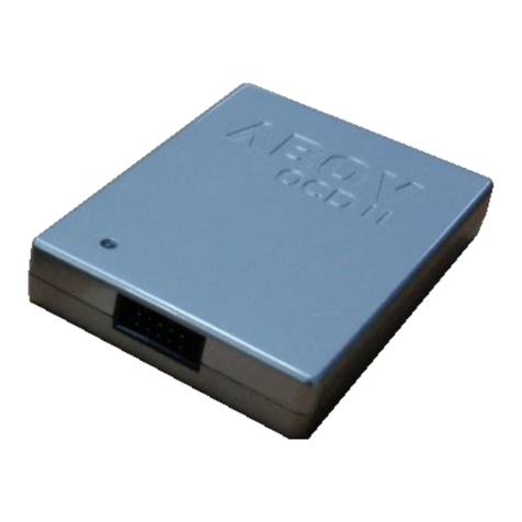
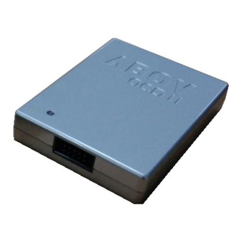
The OCD (On Chip Debug) emulator supports ABOV Semiconductor’s 8051 series MCU emulation.The OCD interface
uses two-wire connection between PC and MCU which is attached to user’s system. The OCD can read or change the
value of MCU internal memory and I/O peripherals. And the OCD also controls MCU internal debugging logic, it means
OCD controls emulation, step run, monitoring, etc.
The OCD debugger program works on Microsoft-Windows NT, 2000, XP, Vista (32-bit) operating system.If you want to
see more details, please refer to OCD debugger manual. You can download debugger S/W and manual from our web-
site (http://www.abov.co.kr).
Connection:
–DSCL (MC95FG308 P06 port)
–DSDA (MC95FG308 P07 port)
OCD connector diagram: Connect OCD with user system
Figure 1.1 debugger and pin description
OCD emulator:
It can write code to MCU device too, because OCD debugger supports ISP (In System Programming). It does not
require additional H/W, except developer’s target system.

6
MC95FG308 / MC95FG208
ABOV Semiconductor Co., Ltd.
1.3.3 Programmer
Single programmer:
PGMplus USB: It programs MCU device directly.
Figure 1.2 PGMplusUSB(Single writer)
Standalone PGMplus:
It programs MCU device directly.
Figure 1.3 Standalone PGMplus(Single writer)

7
MC95FG308 / MC95FG208
ABOV Semiconductor Co., Ltd.
Gang programmer:
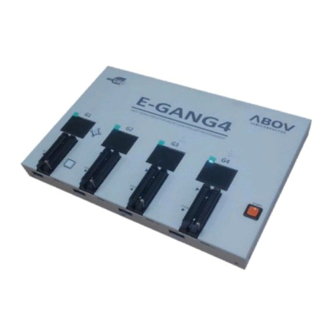
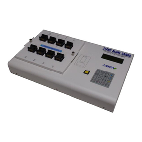
It programs 8 MCU devices at once.So, it is mainly used in mass production factory.
Gang programmer is standalone type, it means it does not require host PC, after a program is downloaded from host
PC to Gang programmer.
Figure 1.4 StandAlone Gang8 (for Mass Production)
On-Board programming :
The program memory of MC95FG308 is FLASH Memory Type. This flash is accessed by serial data format. There are
four pins (DSCL, DSDA, VDD, and VSS) for programming/reading the flash. The MC95FG308 needs only four signal
lines including VDD and VSS pins for programming FLASH with serial protocol. Therefore the on-board programming
is possible if the programming signal lines are considered when the PCB of application board is designed.
Table 1.2 Descriptions of pins used to programming/reading the Flash
Pin name
Main chip
pin name
During programming
I/O
Description
DSCL
P06
I
Serial clock pin. Input only pin.
DSDA
P07
I/O
Serial data pin. Output port when reading and input port when programming.
Can be assigned as input/push-pull output port.
VDD, VSS
VDD, VSS
-
Logic power supply pin.

8
MC95FG308 / MC95FG208
ABOV Semiconductor Co., Ltd.
2 Block diagram
12-BIT
ADC
P25/AN14
P00/AN0
P01/AN1
P02/AN2
P03/AN3
P04/AN4
P05/AN5
P06/AN6
P07/AN7
P15/AN8
P16/AN9
P36/AN10
P37/AN11
P23/AN12
P24/AN13
TIMER
&
PWM
P06/T0O
P15/PWM1CA
P13/PWM1BB
P12/PWM1BA
P11/PWM1AB
P10/T1O/PWM1AA
P07/EC0
P15/PWM1CB
P02/T2O
P03/EC2
P16/T3O
Interrupt
Controller
P10/INT0
P11/INT1
P12/INT2
P13/INT3
P30/INT4
P31/INT5
P32/INT6
P33/INT7
SPI
P00/SS0
P01/SCK0
P02/MOSI0
P03/MISO0
USART0
P00/SS0
P01/ACK0
P02/TxD0
P03/RxD0
USART1
P34/SS1
P35/ACK1
P36/TxD1
P37/RxD1
I2C
P07(P26)/SDA
P06(P25)/SCL
On-Chip
Debug
M8051
CORE
EEPROM
(512B)
RAM
(512B)
FLASH
(8K byte)
Power on
Reset
Brown Out
Detector
INT-RC OSC
8MHz
INT-RING OSC
1MHz
Voltage
Down
Convertor
P0
PORT
P1
PORT
P2
PORT
P3
PORT
BIT
WDT
WT
BUZZER
Analogue
Comparator
P12/BUZ
ACOUT/P06
AC+/P05
AC-/P04
P37~P30
P26~P20
P16~P10
P06~P00
DSDA/P07DSCL/P06
VDD VSS
CLOCK
SYSTEM
CON
SUBXIN/P04
SUBXOUT/P05
XIN/P20
XOUT/P21
RESETB/P22
Figure 2.1 Block diagram of MC95FG308

9
MC95FG308 / MC95FG208
ABOV Semiconductor Co., Ltd.
3 Pin assignment
MC95FG308
1
2
3
4
5
6
7
8
(TxD0) / INT6 / P32
9
10
11
12
13
14
15
16
32
31
30
29
28
27
26
25
24
23
22
21
20
19
18
17
(RxD0) / INT7 / P33
SXIN / AC- / AN4 / P04
SXOUT / AC+ / AN5 / P05
(DSCL) / ACOUT / AN6 / T0O / SCL / P06
(DSDA) / AN7 / EC0 / SDA / P07
AN14 / (SCL) / P25
(SDA) / P26
VDD
PWM1AA / T1O / INT0 / P10
PWM1AB / INT1 / P11
PWM1BA / BUZ / INT2 / P12
PWM1BB / (T0O) / P13
PWM1CA / (EC0) / P14
AN8 / PWM1CB / P15
SS1 / P34
P31 / INT5
P30 / INT4
P03 / RxD0 / MISO0 / EC2 / AN3
P02 / TxD0 / MOSI0 / T2O / AN2
P01 / ACK0 / SCK0 / AN1
P00 / SS0 / AN0 / AVref
P24 / AN13
P23 / AN12
VSS
P22 / RESETB
P21 / XOUT
P20 / XIN
P16 / INT3 / T3O / PWM3 / AN9
P37 / RxD1 / AN11
P36 / TxD1 / AN10
P35 / ACK1
NOTE)
1. If 28PKG, Pin 7, 8, 25 and 26 in 32-pin package are removed and their function can’t operate.
2. If 20PKG, Pin 1, 2, 31, 32, 15, 16, 17, 18, 7, 8, 25 and 26 in 32-pin package are removed and their
function can’t operate.
3. If 16PKG, Pin 13, 14, 19, 20, 1, 2, 31, 32, 15, 16, 17, 18, 7, 8, 25 and 26 in 32-pin package are removed
and their function can’t operate.
4. On On-Chip Debugging, ISP uses P0[7:6] pin as DSCL, DSDA.
5. The outside pin operation has higher priority than the inside pin operation. Ex) In pin32, if P03, RxD0,
MISO0, EC2 and AN3 are set, AN3 will be operated.
Figure 3.1 MC95FG308 32SOP pin assignment

10
MC95FG308 / MC95FG208
ABOV Semiconductor Co., Ltd.
MC95FG308U
1
2
3
4
5
6
n
7
8
32 31 30 29 28 27 26 25
P32 / INT6 / (TxD0)
P33 / INT7 / (RxD0)
P04 / AN4 / AC- / SXIN
P05 / AN5 / AC+ / SXOUT
(DSDA) / AN7 / EC0 / SDA / P07
AN14 / (SCL) / P25
(SDA) / P26
VDD
PWM1AA / T1O / INT0 / P10
PWM1AB / INT1 / P11
PWM1BA / BUZ / INT2 / P12
P13 / (T0O) / PWM1BB
P14 / (EC0) / PWM1CA
P15 / PWM1CB / AN8
P34 / SS1
P35 / ACK1
P36 / TxD1 / AN10
P37 / RxD1 / AN11
P16 / INT3 / T3O / PWM3 / AN9
P20 / XIN
P21 / XOUT
P22 / RESETB
VSS
P23 / AN12
P24 / AN13
P00 / SS0 / AN0 / AVref
P01 / ACK0 / SCK0 / AN1
P02 / TxD0 / MOSI0 / T2O / AN2
P03 / RxD0 / MISO0 / EC2 / AN3
P30 / INT4
P31 / INT5
(DSCL)/ACOUT/AN6/T0O/SCL/P06
9 10 11 12 13 14 15 16
24
23
22
21
20
19
18
17
Figure 3.2 MC95FG308 32QFN pin assignment

11
MC95FG308 / MC95FG208
ABOV Semiconductor Co., Ltd.
MC95FG308L
1
2
3
4
5
6
7
8
32 31 30 29 28 27 26 25
P32 / INT6 / (TxD0)
P33 / INT7 / (RxD0)
P04 / AN4 / AC- / SXIN
P05 / AN5 / AC+ / SXOUT
(DSDA) / AN7 / EC0 / SDA / P07
AN14 / (SCL) / P25
(SDA) / P26
VDD
PWM1AA / T1O / INT0 / P10
PWM1AB / INT1 / P11
PWM1BA / BUZ / INT2 / P12
P13 / (T0O) / PWM1BB
P14 / (EC0) / PWM1CA
P15 / PWM1CB / AN8
P34 / SS1
P35 / ACK1
P36 / TxD1 / AN10
P37 / RxD1 / AN11
P16 / INT3 / T3O / PWM3 / AN9
P20 / XIN
P21 / XOUT
P22 / RESETB
VSS
P23 / AN12
P24 / AN13
P00 / SS0 / AN0 / AVref
P01 / ACK0 / SCK0 / AN1
P02 / TxD0 / MOSI0 / T2O / AN2
P03 / RxD0 / MISO0 / EC2 / AN3
P30 / INT4
P31 / INT5
(DSCL)/ACOUT/AN6/T0O/SCL/P06
9 10 11 12 13 14 15 16
24
23
22
21
20
19
18
17
Figure 3.3 MC95FG308 32LQFP pin assignment

12
MC95FG308 / MC95FG208
ABOV Semiconductor Co., Ltd.
MC95FG308
1
2
3
4
5
6
7
8
(TxD0) / INT6 / P32
9
10
11
12
13
14
28
27
26
25
24
23
22
21
20
19
18
17
16
15
(RxD0) / INT7 / P33
SXIN / AC- / AN4 / P04
SXOUT / AC+ / AN5 / P05
(DSCL) / ACOUT / AN6 / T0O / SCL / P06
(DSDA) / AN7 / EC0 / SDA / P07
VDD
PWM1AA / T1O / INT0 / P10
PWM1AB / INT1 / P11
PWM1BA / BUZ / INT2 / P12
PWM1BB / (T0O) / P13
PWM1CA / (EC0) / P14
AN8 / PWM1CB / P15
SS1 / P34
P31 / INT5
P30 / INT4
P03 / RxD0 / MISO0 / EC2 / AN3
P02 / TxD0 / MOSI0 / T2O / AN2
P01 / ACK0 / SCK0 / AN1
P00 / SS0 / AN0 / AVref
VSS
P22 / RESETB
P21 / XOUT
P20 / XIN
P16 / INT3 / T3O / PWM3 / AN9
P37 / RxD1 / AN11
P36 / TxD1 / AN10
P35 / ACK1
Figure 3.4 MC95FG308 28SOP/TSSOP pin assignmemt

13
MC95FG308 / MC95FG208
ABOV Semiconductor Co., Ltd.
MC95FG208
1
2
3
4
5
6
7
8
SXIN / AC- / AN4 / P04
9
10
20
19
18
17
16
15
14
13
12
11
SXOUT / AC+ / AN5 / P05
(DSCL) / ACOUT / AN6 / T0O / SCL / P06
(DSDA) / AN7 / EC0 / SDA / P07
VDD
PWM1AA / T1O / INT0 / P10
PWM1AB / INT1 / P11
PWM1BA / BUZ / INT2 / P12
PWM1BB / (T0O) / P13
PWM1CA / (EC0) / P14
P03 / RxD0 / MISO0 / EC2 / AN3
P02 / TxD0 / MOSI0 / T2O / AN2
P01 / ACK0 / SCK0 / AN1
P00 / SS0 / AN0 / AVref
VSS
P22 / RESETB
P21 / XOUT
P20 / XIN
P16 / INT3 / T3O / PWM3 / AN9
P15 / PWM1CB / AN8
Figure 3.5 MC95FG208 20SOP/TSSOP pin assignmemt
MC95FG208
1
2
3
4
5
6
7
8
SXIN / AC- / AN4 / P04 16
15
14
13
12
11
10
9
SXOUT / AC+ / AN5 / P05
(DSCL) / ACOUT / AN6 / T0O / SCL / P06
(DSDA) / AN7 / EC0 / SDA / P07
VDD
PWM1AA / T1O / INT0 / P10
PWM1AB / INT1 / P11
PWM1BA / BUZ / INT2 / P12
P03 / RxD0 / MISO0 / EC2 / AN3
P02 / TxD0 / MOSI0 / T2O / AN2
P01 / ACK0 / SCK0 / AN1
P00 / SS0 / AN0 / AVref
VSS
P22 / RESETB
P21 / XOUT
P20 / XIN
Figure 3.6 MC95FG208 16SOP/TSSOP pin assignmemt

14
MC95FG308 / MC95FG208
ABOV Semiconductor Co., Ltd.
4 Package Diagram
Figure 4.1 32-Pin SOP Package

15
MC95FG308 / MC95FG208
ABOV Semiconductor Co., Ltd.
Figure 4.2 32-Pin QFN Package

16
MC95FG308 / MC95FG208
ABOV Semiconductor Co., Ltd.
Figure 4.3 32-Pin LQFP Package

17
MC95FG308 / MC95FG208
ABOV Semiconductor Co., Ltd.
Figure 4.4 28-Pin SOP Package

18
MC95FG308 / MC95FG208
ABOV Semiconductor Co., Ltd.
Figure 4.5 28-Pin SOP Package (continue)

19
MC95FG308 / MC95FG208
ABOV Semiconductor Co., Ltd.
Figure 4.6 28-Pin SOP Package

20
MC95FG308 / MC95FG208
ABOV Semiconductor Co., Ltd.
Figure 4.7 28-Pin TSSOP Package
This manual suits for next models
10
Table of contents
Other Abov Microcontroller manuals

Abov
Abov A96T418GDN User manual

Abov
Abov MC96F6432A User manual

Abov
Abov MC95FG0128A User manual

Abov
Abov MC96F8204 Series User manual

Abov
Abov A31G213CLN User manual

Abov
Abov MC96F6432 Series User manual

Abov
Abov A31T216RLN User manual

Abov
Abov MC96FM204 User manual

Abov
Abov A96G140 User manual

Abov
Abov AC33M8128L User manual

Abov
Abov MC97F6108A User manual

Abov
Abov MC96FR364B User manual

Abov
Abov MC97F60128 User manual

Abov
Abov EW8051 User manual

Abov
Abov A96G140 User manual

Abov
Abov A96G150 User manual

Abov
Abov MC97F2664 User manual
Abov
Abov A96G140 User manual
Abov
Abov MC96F6432S Series User manual

Abov
Abov 8-bit MCU User manual